Table of Contents
Advertisement
Quick Links
Advertisement
Table of Contents

Subscribe to Our Youtube Channel
Related Manuals for BK Precision 4071


Summary of Contents for BK Precision 4071
- Page 1 User’s Manual Model 4071 31.5MHz Multi Function Arbitrary Waveform Generator...
- Page 3 B&K Precision Model 4071 User’s Manual K Precision Corp. ALL RIGHTS RESERVED PRODUCT AND DOCUMENTATION NOTICE: B documentation without prior notice. Information furnished by B K Precision is believed to be accurate and reliable. However, B+K Precision assumes no responsibility for its use, nor for any infringement of patents, or other rights of third parties, which may result from its use.
-
Page 4: Table Of Contents
1.0 Introduction 1.1 Description ...2 1.2 Feature summary...3 2.0 Installation and setup Detail explanation of input and output connectors ...4 3.0 Operating controls and keys 3.1 Mode key...8 3.2 Field arrow keys...8 3.3 Store/Recall key ...8 3.4 Offset key...8 3.5 Trigger key...9 3.6 Numeric keys (0 to 9, -.) ...9 3.7 é, ê, è, ç... - Page 5 5.26 Voltage Controlled Oscillator (VCO) mode...39 6.0 Remote operation 6.1 Introduction...40 6.2 Hookup...40 6.3 Checking your connection with Hyper Terminal...40 6.4 Operation ...41 6.5 Programming Rules...41 6.6 Remote control command List...42 6.7 Examples...45 7.0 Arbitrary waveform system 7.1 Arbitrary Waveform Quick Start Guide...46 7.2 Introduction to the Arbitrary Waveform Generator 7.2.1 Description of the Arbitrary Waveform System...47 7.2.2 Feature Summary ...48...
-
Page 6: Introduction
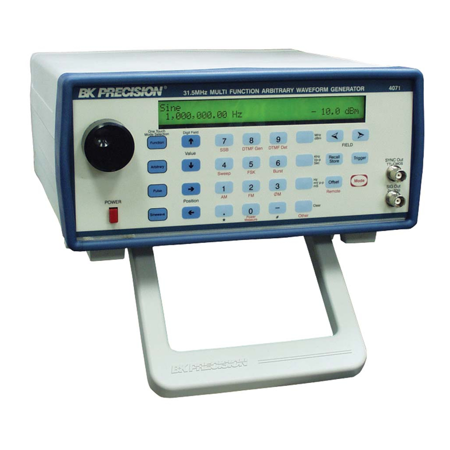
1.0 Introduction Figure 1.0-1: The BK Precision model 4071 This manual contains operating instructions for the BK Precision Model 4071 Signal Generation and Processing Engine. Complete specifications for the Model 4071 are given in Chapter 9. BK Precision 4071 User Manual Rev.2.2... -
Page 7: Description
The 4071 designed to supply an output signal level of 20.0 Vp -p with an offset voltage of +/- 6.0V. The output impedance is 50O; therefore the 50O loaded output level is 10.0 Vp -p, with an offset voltage capability of +/- 6.0V in Function, Arbitrary and Pulse modes. -
Page 8: Feature Summary
Internal/External FSK Data Modulation Options (contact factory for availability): DTMF Generation DTMF Detection Voltage & Power Measurement Burst (Continuous or Int/Ext trig) Sweep (Linear/Log/Continuous/Triggered/Up/Down) Dualtone Generation Voltage Controlled Oscillator (VCO) High stability time-base DC Operation BK Precision 4071 User Manual Rev.2.2... -
Page 9: Installation And Setup
This section discusses how to properly connect the 4071 to your equipment. The following diagrams identify the connectors and show typical hookups. 1. SYNC out connector This connector provides a TTL/CMOS signal, +5V logic level useful for driving digital circuitry. This output is capable of driving TTL or CMOS loads with current capability +/- 24 mA. - Page 10 This input is high impedance (about 30KO). It was made high impedance to avoid loading down the circuit supplying the signal. This input is DC coupled within the 4071. The signal on this input is internally low pass filtered to a cutoff frequency of 50KHz.
- Page 11 Be careful to ensure that the input signal does not exceed the +/- 10V limit. Permanent damage to this input may *** Caution *** result by exceeding this input voltage limit. BK Precision 4071 User Manual Rev.2.2...
-
Page 12: Rs232 Interface Connector
For further information, refer to chapter 6. 8. Line in connector A standard IEC power cord inserts directly into the back of the 4071. The input is auto-ranging and may be 100- 240VAC, 47-63 Hz. Figure 2.0-5: Rear panel connectors... -
Page 13: Operating Controls And Keys
3.0 Operating controls and keys. 3.1 Mode key The Mode key is used to change the operating mode of the 4071. When pressed, the LCD display is cleared and the question Mode? is displayed. The Mode key acts as a shift type key in that the meaning of each button on the front panel changes to that described by the red wording beneath it. -
Page 14: Offset Voltage
The loaded output cannot swing higher than +6.0V or lower than -6.0V. Therefore: The 4071 can be used as a variable voltage source by setting the output frequency to 0.0 Hz while in Sinewave mode. Then set the offset voltage to the desired output voltage. Remember, the output impedance is 50 ohms. Up to +/- 70 mA can be drawn from the output under these conditions. -
Page 15: Clear Key
After pressing one of these keys, the 4071 will make a double clicking noise to indicate that the value has been accepted. If the entered value is outside the allowable range for the field, the 4071 will give an error beep and set the value to its upper or lower limit. -
Page 16: Operating Guide
4.4 Operating mode selection. If you wish to select a new operating mode for the 4071, press the red Mode key once. When pressed, the LCD display is cleared and the question Mode? is displayed. The Mode key acts as a shift type key in that the meaning of each button on the front panel changes to that described by the red wording beneath it. -
Page 17: Changing Values
Alternatively, you can turn the rotary knob clockwise or counterclockwise to adjust the digit's value. Attempting to set a parameter to a value outside the allowable range will cause the 4071 to beep and set the parameter to its maximum or minimum permissible value. -
Page 18: Mode Descriptions
Sinewawe One touch mode selection key NOTE: In this mode you can set the output frequency to 0 Hz and, by specifying an offset voltage, use the 4071 as a variable voltage source (with a 50O output impedance). Up to +/- 70 mA can be drawn from the SIG Out output. -
Page 19: Internal Am Mode
This TTL compatible input can be used to gate the output signal on or off. A logic high level turns off the output. For further information on the Ext Gating Input, refer to section 2.0. Percent Mod: 100% PEP level: -10.0 dBm Figure 5.2-1: Internal AM mode display BK Precision 4071 User Manual Rev.2.2... -
Page 20: External Am Mode
This TTL compatible input can be used to gate the output signal on or off. A logic high voltage turns off the output. For further information on the Ext Gating Input, refer to section 2.0. Input gain: .999 PEP level: -10.0 dBm Figure 5.3-1: External AM mode display BK Precision 4071 User Manual Rev.2.2... -
Page 21: Internal Fm Mode
This TTL compatible input can be used to gate the output signal on or off. A logic high voltage turns off the output. For further information on the Ext Gating Input, refer to section 2.0. Pk dev: 10,000 Hz Figure 5.4-1: Internal FM mode display BK Precision 4071 User Manual Rev.2.2 -10.0 dBm... -
Page 22: External Fm Mode
This TTL compatible input can be used to gate the output signal on or off. A logic high voltage turns off the output. For further information on the Ext Gating Input, refer to section 2.0. Pk dev: 10,000 Hz Figure 5.4-1: External FM mode display BK Precision 4071 User Manual Rev.2.2 -10.0 dBm... -
Page 23: Internal Pm Mode
This TTL compatible input can be used to gate the output signal on or off. A logic high voltage turns off the output. For further information on the Ext Gating Input, refer to section 2.0. Pk dev: 180 deg Figure 5.6-1: Internal PM mode display BK Precision 4071 User Manual Rev.2.2 -10.0 dBm... -
Page 24: External Pm Mode
This TTL compatible input can be used to gate the output signal on or off. A logic high voltage turns off the output. For further information on the Ext Gating Input, refer to section 2.0. Pk dev: 180 deg Figure 5.7-1: External PM mode display BK Precision 4071 User Manual Rev.2.2 -10.0 dBm... -
Page 25: Sweep Mode
3. Sending an ASCII "T" to the RS-232 port The 4071 will simultaneously accept a trigger from all of the above sources. To set Continuous type sweep, press 1. To set Triggered type sweep, press 0. Pressing any arrow key or rotating the wheel will toggle the sweep type between Continuous and Triggered. - Page 26 A logic low-to-high transition on this input will trigger the sweep. This input has an internal pull down resistor so that the input is held at a logic low when this input is left unconnected. BK Precision 4071 User Manual Rev.2.2...
-
Page 27: Internal Fsk Mode
NOTE: For wideband FSK (where the difference between Mark and Space frequencies is > 1.0 MHz), the output level may shift slightly between the mark and space frequencies. The 4071 has internal leveling circuitry, which is disabled in this mode, in order to offer higher FSK modulation rates. -
Page 28: External Fsk Mode
NOTE: For wideband FSK (where the difference between Mark and Space frequencies is > 1.0 MHz), the output level may shift slightly between the mark and space frequencies. The 4071 has internal leveling circuitry, which is disabled in this mode, in order to offer faster FSK switching rates. -
Page 29: Burst Mode
In triggered burst mode, the output frequency is set to 0 Hz and the unit awaits a trigger condition. When a trigger condition occurs, the 4071 delays for a time specified in the Off time field and then sets the output frequency to the specified value. -
Page 30: Internal Ssb Mode
This TTL compatible input can be used to gate the output signal on or off. A logic high voltage turns off the output. For further information on the Ext Gating Input, refer to section 2.0. Upper Sideband Figure 5.12-1: Internal SSB mode display BK Precision 4071 User Manual Rev.2.2 -10.0 dBm... -
Page 31: External Ssb Mode
This TTL compatible input can be used to gate the output signal on or off. A logic high voltage turns off the output. For further information on the Ext Gating Input, refer to section 2.0. Upper Sideband Figure 5.13-1: External SSB mode display BK Precision 4071 User Manual Rev.2.2 -10.0 dBm... -
Page 32: Dtmf Generation Mode
DTMF detection systems. By sending a string of digits to dial to the RS-232 port, the 4071 can be used as a speed dialer; these digits are queued and dialed with the specified duration and delay between digits. - Page 33 3. DTMF Delay The 4071 will delay generation of the DTMF tone by the time specified in this field. This parameter is used primarily to add an inter-digit delay between dialed digits so that the user can send a string of ASCII digits to the RS-232 port for speed dialing.
-
Page 34: Dtmf Detection Mode
When the 41st digit is detected, this line of the display is cleared and the new digit is printed on the left hand side. All detected digits are sent to the terminal port. By connecting a computer to the terminal port, the 4071 can be used as DTMF detection peripheral. -
Page 35: Power & Voltage Measurement Mode
The value of this load resistor is referred to here as the "system impedance" which must be specified by the user. As opposed to instruments, which use a fixed value for this impedance (i.e. 50 or 600 O) the 4071 allows any value from 1 to 999 ohms to be used for power calculations. -
Page 36: Arbitrary Mode
5.21 Other mode This mode displays a menu of extended modes that are available on the 4071. It is used to present additional operating modes that are not printed on the front keypad. Pressing Mode key once and then the Clear key access... -
Page 37: Internal Bpsk Mode
+10V) will turn off the output signal. A logic low voltage on this jack (0V to -10V) will leave the output signal on. For further information on the Ext Gating Input, refer to section 2.0. Figure 5.22-1: Internal BPSK mode display BK Precision 4071 User Manual Rev.2.2 - 10.0 dBm... -
Page 38: External Bpsk Mode
Apply the digital data to be modulated on this connector. When this input is high, the output phase is advanced 180 degrees. When this input is low, the output frequency is retarded 180 degrees. (I.e. this input switches the sign of the output carrier). Figure 5.23-1: External BPSK mode display BK Precision 4071 User Manual Rev.2.2 - 10.0 dBm... -
Page 39: Dualtone Generation Mode
SIG Out connector. Into an open circuit, the output swing will be twice the value entered. Offset You can enter an offset voltage for the output signal. For more information on output offsets refer to section 4.4. Toff: 0 mS BK Precision 4071 User Manual Rev.2.2 Ø: 0 -10.0 dBm... - Page 40 1 mS 480 Hz 2,000 mS 620 Hz 500 mS 620 Hz 250 mS 620 Hz 1 mS 440 Hz various BK Precision 4071 User Manual Rev.2.2 Off Time (Toff) 0 mS 4,000 mS 500 mS 250 mS 0 mS various...
-
Page 41: Data Modulation Mode
Data Modulation mode operates in a triggered burst mode. The Data Modulation mode starts by setting the output frequency to 0 Hz and awaiting a trigger condition. When a trigger condition occurs, the 4071 examine the first data bit of the binary message and set the output frequency to the Mark frequency if the bit is a 1 or to the Space frequency if the bit is a 0. -
Page 42: Example Message
- This is the second 16 bits of the binary message. Since the message is only 18 bits long, only the MSB and the next lower bit will be sent (in this case a 1 then a 0). After the last bit is sent, the 4071 turns off the carrier and awaits another trigger condition. -
Page 43: Saving The Message
When a trigger condition occurs, the unit will turn on the carrier and modulate the carrier until all bits have been sent out. After the message has been transmitted, the 4071 will turn off the carrier and await another trigger event. -
Page 44: Voltage Controlled Oscillator (Vco) Mode
Apply the control voltage to this connector. For this mode, the input signal may be in the -5.0V to +5.0V range. Levels outside this range will be clipped by limiting circuitry. Start: Figure 5.26-1: VCO mode display *** Caution*** Levels outside ±25V may damage the 4071. BK Precision 4071 User Manual Rev.2.2 0 Hz -10.0 dBm... -
Page 45: Remote Operation
To use the remote control feature, you must attach the serial port on your computer or terminal to the RS-232 connector on the rear of the 4071. On PC serial port is a male 9 pin or 25-pin connector. The wiring is different for each type of connector. -
Page 46: Remote Control Operation
Verify that you are using the correct COM port. Check your cabling. If you see the command menu, you have verified that the 4071 is properly cabled to the computer, and that you are certain which COM port you are using. -
Page 47: Remote Control Command List
This command resets the 4071 to the Sine wave mode and turns the cursor off. The output-offset voltage is set to 0.0V. When writing control software for the 4071, it is a good idea to issue this command first so that the 4071 is in a known state before further commands are issued. - Page 48 E1,0 - Enable, Disable LCD echo to terminal This command enables (or disables) a feature where the 4071 prints the contents of the LCD display to the terminal port whenever the display changes. It is useful to enable this feature when you cannot see the LCD display.
- Page 49 ^E - Return a ^C Sending an ASCII control E character (ASCII value 5) to the 4071 will cause it to echo back a control C (ASCII value 3). Remote control programs could use this future to confirm current settings of remotely controlled 4071.
-
Page 50: Examples
NOTE: You do not need spaces between the characters. They were added here only to make the commands more readable. This command sequence breaks down as follows: - Set 4071 to Sinewave mode - Move cursor to field 1 (frequency field) 3.141Z - Enter a freq. -
Page 51: Arbitrary Waveform Mode
4071 \arb\examples directory. Connect a serial port on you PC to the serial port connector on the rear of the 4071. You may temporarily detach your serial mouse if needed to free up a serial port. (Mouse operation will be restored after the download). -
Page 52: Introduction To The Arbitrary Waveform Generator 7.2.1 Description Of The Arbitrary Waveform System
7.2.1 Description of the Arbitrary Waveform Generator The Arbitrary Mode lets the user design custom waveforms on a PC and download them to the 4071 for generation including Arbitrary Waveform system is a fully featured Function Generator. Function generator offers a set of pre- stored waveforms. -
Page 53: Feature Summary
7.3 Switching Modes Switching to Arbitrary Waveform / Function Generator / Pulse Generator Mode In order to switch 4071 unto one of those modes, press one Touch Mode selection keys on the front panel. BK Precision 4071 User Manual Rev.2.2... -
Page 54: Arbitrary Waveform Mode
- The unit provides the master timing signals for locking multiple 4071 Arb generators together. Lock Slave - The unit receives all timing signals from a master unit. Used when locking multiple 4071 Arb’s together. For more information on locking Arb’s together, see the section 7.9. -
Page 55: Function Generator Mode
3. Sending an ASCII "T" to the RS-232 port The 4071 will simultaneously accept a trigger from all of the above sources. To set Continuous mode, press 1. To set triggered mode, press 0. Pressing any arrow key or rotating the wheel will toggle the run mode between Continuous and Triggered. -
Page 56: Pulse Generator Mode
½ the specified level into a 50O load (or 0V to the specified level into an open circuit). Offset You can enter a DC offset voltage by pressing the Offset key. For more information see section 4.4. Pos Only? N Duty Cycle: 50 % BK Precision 4071 User Manual Rev.2.2 1,000 mV... -
Page 57: Downloading Arbitrary Waveforms
To download Arbitrary Waveform data to the 4071, you must connect the serial port on your computer to the RS-232 port on the back of the 4071. For more detail information on this, refer to the chapter 6.2 On the host computer, you may use the supplied DOS program WAVELOAD.EXE or you may send the data to the 4071 from... -
Page 58: Using Your Own Program
5.20. You do not need to tell the 4071 how many points are in the waveform, or which point is the last. If the 4071 does not receive any characters over the serial port for a 1 second time-out, then the 4071 assumes that all arbitrary waveform points have been received. -
Page 59: Data Formats
0 3. You do not have to include an exponent (i.e. e-5). If no exponent is given, the 4071 assumes that the exponent is 4. Space characters are not allowed between the mantissa and the exponent. -
Page 60: Time & Value Floating Point Format (.Csv, .Prn)
-.278991e-03 .309017x The “x” character at the end denotes the end of the data and is optional. If the “x” character is missing, the 4071 will assume all data has been sent after 1-second timeout. BK Precision 4071 User Manual Rev.2.2... -
Page 61: Digital Format
All rules for this format are identical to those for Floating Point Format, except that the Time or Point Number value need not be between +1.0 and -1.0 in value since the 4071 only sees if the value is zero or nonzero. Also, the “P”... -
Page 62: Integer Format
-1511 -320 +12, The “x” character denotes the end of the data and is optional. If the “x” character is missing, the 4071 will assume all data has been sent after 1-second timeout. -2047 ---- -1024 --- 0 ---- 1024 ---- 2047 -1.0... -
Page 63: Hexadecimal Format
This format sends the same two's complement data that Binary format uses, except that each nibble (4 bits) of the hex value is represented by an ASCII character. Each data point is a 16-bit value, which is sent to the 4071 as 4 ASCII characters. -
Page 64: Binary Format
This is the fastest way to send points to the 4071 since it transfers the data point with only 2 characters. (It is also the least forgiving as far as getting the data sent correctly). Each data point is a 16-bit word, which is sent to the 4071 in two bytes. The high byte is sent first, followed by the low byte. -
Page 65: Multiple Units Locking
“jump to the first sample point” at the same time. With these two signals, all units are guaranteed to be on the same sample point at the same time. The 4071 use one arbitrary waveform generator as a “Master”... - Page 66 By changing which point in the waveform is jumped to, the starting phase of the waveform may be adjusted. The 4071 has a phase offset field which allows the user to specify a starting phase from 0 degrees to 359.99 degrees.
-
Page 67: Example Arbitration Program Arb.bas
ARB.BAS is a program written in Microsoft Quick Basic, which calculates the points of a sinewave and downloads them to the 4071 as an arbitrary waveform. The program can generate the waveform in all of the supported formats (Floating Point, Integer, Hexadecimal, and Binary) and shows how SYNC Out can be asserted during waveform points. - Page 68 ' All points have now been generated and sent to the 4071. ' When the 4071 hasn't received any chars over the serial port for a ' 1 second time-out, it assumes that all points have been sent and starts ' generating the waveform.
- Page 69 ' Before the first data point is sent, a Header consisting of two characters ' is sent to the 4071. The first character of this header is a "W", which ' tells the 4071 to expect arbitrary waveform data points. The second ' character of the header tells the 4071 what data format to expect, ' "F"...
- Page 70 +1.0 ' Rules for Integer format: ' 1. The 4071 expects all Integer values to be between -2047 and +2047. ' If a number falls outside that range, the number is set to -2047 or +2047. ' These correspond to the peak values of the waveform. If the output voltage ' level were set for 5V p-p, for example, then +2047 corresponds to +2.5V...
- Page 71 (4 bits) of the hex value is represented by an ASCII character. Each point is a 16 bit word which is sent to the 4071 with 4 characters. Each character represents 4 bits of the 16 bit value: 0000 to 1001 - Represented by an ASCII "0"...
- Page 72 2 characters. It is also the least forgiving as far as getting the data sent correctly. Each data point is a 16 bit word which is sent to the 4071 in two bytes. The high byte is sent first, followed by the low byte.
- Page 73 ' The 4071 expects the high byte first so we must reverse the two so we get the proper byte order (i.e. high byte then low byte) high = INT(a / 256) low = a MOD 256 a = low * 256 + high IF a >...
-
Page 74: Wiring Diagram
Description The DC Operation Option allows the user to power the 4071 from a DC voltage source in the 9-36 VDC range. The user may easily switch between the AC Line supply and a DC source. This option is most useful for service and remote applications where AC power is not available. -
Page 75: Operating Modes
Frequency: 0 Hz to 2 MHz in 1 Hz steps Duty cycle: 0% to 100% in 1% steps Tr, Tf: <40 nS (10% to 90%, 1Vp -p) Variable in amplitude & offset. TTL/CMOS output also. BK Precision 4071 User Manual Rev.2.2... -
Page 76: Software Cd
The compact disk, which accompanies this manual, contains a number of useful utilities and example programs, which are in directory /disc 4071. Due to similarity in firmware structure BK models 4070A and 4071 both are compatible with this software, except frequency range. Below is a list of the directories on this disk and a description of the files within each. -
Page 77: Hardware Setup
The program illustrates several basic techniques for remotely controlling the 4071 with a control program. The program begins by showing how to detect the presence of the 4071 on the serial port. It also shows how to set the operating mode and enter parameters such as frequency and level. The program also parses information sent from the 4071 to the host computer and displays that information on the screen. - Page 78 '----------- Make sure a 4071 is attached to the serial port -------------- ' If we send the 4071 a control E character, it will respond with a control C. ' We use this feature to see if a 4071 is attached.
- Page 79 - Move cursor to field 0 (turns cursor off) PRINT #1, "A F1 18.432Z F2 0.0Z F0"; ' After the 4071 executes each command, it will return a prompt character (">"). We wish ' to wait until after all prompts have ' come in, since that's when the 4071 has finished executing the last command.
- Page 80 CALL Delay(.8) IF LOC(1) <> 0 THEN GOTO GetRespLoop1 RETURN '------------------------------------------------------------------------------ Wait for a command prompt from 4071 ' Returns A$ = all stuff received before the command prompt. '------------------------------------------------------------------------------ PromptWait: ' If we have no chars in Rx buffer, wait until we have 1 or more a$ = ""...
- Page 81 Wait for x mS ' Returns no. of secs since midnight. ' Example: 65445.15 ' Do a x mS delay Wait for a keypress ' Wait for keypress to continue BK Precision 4071 User Manual Rev.2.2...
-
Page 82: Appendix B Application Example: Television Remote Control
This chapter contains an example program written in Microsoft QuickBasic for controlling the 4071 remotely. It is used here to drive an infrared LED to issue commands to a TV or a VCR. It uses the 4071 in Burst mode to emulate the same waveforms used in many infrared remote control transmitters. - Page 83 Array(3) = ChannelDown Array(4) = VolumeUp Array(5) = VolumeDown ' Open serial port 1 for communication with the 4071 with these parameters: ' Ignore the CD,CTS,DCD flow control lines ' Set a 5 sec maximum time-out for basic to open the port...
- Page 84 '----------- Make sure a 4071 is attached to the serial port -------------- ' If we send the 4071 a control E character, it will respond with a control C. We use ' this feature to see if a 4071 is attached. If a 4071 cannot be found, wait until ' one is attached.
- Page 85 ' Dump the "t"'s to the 4071 ' The 4071 will now trigger a burst for each "t" char we sent it. After the 4071 ' executes each "t" command, it will return a prompt character (">"). We wish to wait ' until after all prompts have come in, since that's when the 4071 has finished ' processing the last "t".
-
Page 86: Limited Two-Year Warranty
This warranty gives you specific rights and you may have other rights, which vary from state-to-state. Model Number: ______________ Limited Two-Year Warranty Date Purchased: __________ BK Precision 4071 User Manual Rev.2.2 22820 Savi Ranch Parkway Yorba Linda, CA 92887 www.bkprecision.com... -
Page 87: Service Information
America shipping fees contact B&K Precision Corp.. B&K Precision Corp. 22820 Savi Ranch Parkway Yorba Linda, CA 92887 Email: service@bkprecision.com Include with the instrument your complete return shipping address, contact name, phone number and description of problem. BK Precision 4071 User Manual Rev.2.2... - Page 88 PN: 481-419-9-001 Printed in the U.S.A. 2002 B&K Precision Corp. 22820 Savi Ranch Pkwy Yorba Linda, CA 92887 TEL: 714-921-9095 FAX: 714-921-6422 www.bkprecision.com...
Need help?
Do you have a question about the 4071 and is the answer not in the manual?
Questions and answers