Advertisement
Quick Links
Download this manual
See also:
User Manual
Service manual
Carony Go
Carony Drive
(Discontinued)
Safety
General
Service and
maintenance
Mechanics
Advertisement

Related Manuals for Autoadapt Carony Go


Summary of Contents for Autoadapt Carony Go
-
Page 1: Service Manual
Service manual Carony Go Carony Drive (Discontinued) Safety General Service and maintenance Mechanics... -
Page 3: Maintenance
Service manual Carony Go/Drive Safety 0:! Technical data General 1:! Service check-ups Service and 1:2 Instructions for service and maintenance maintenance 1:3 Updates 2:1 Description Mechanics 2:2 Exploded views and components 2:3 Trouble shooter 2:4 Repair manual 3:1 Description / Programming... - Page 5 Batteries contain sulphuric acid which is very corrosive to the human body and parts of the Carony Go. Batteries give off Hydrogen gas when charged. This gas is together with oxygen very explosive.
- Page 7 General 0:1 Technical data Carony Drive Carony Go Drive: Carony Go/ Drive Total width, with air tyres 62 cm Range 25 km Total width, puncture free wheels 60,9 cm Max speed 6,5 km/h Length 75 cm Max reverse speed 3 km/h...
- Page 8 0:1 Technical data Carony Go Measurements for TURNOUT applications INSIDE THE VEHICLE: Total height with TURNOUT Measured from vehicle sill + Carony rails and seat: 840 mm vehicle sill Carony rails Turnout + Carony rails + BEV seat = 950 mm Measured from where the sill moulding starts to bend upwards.
- Page 9 0:1 Technical data Carony Go Measurements for TURNY applications Carony rails Turny seat raising Carony rails spacer 35 mm Turny + Carony rails + Bev-seat = 1050 mm This measure depends on the user. A tall per- son, who is unable to bend the neck, needs more space.
- Page 10 0:1 Technical data...
-
Page 11: Service And Maintenance
Service and Maintenance 1:1 Service check-ups When servicing the Carony Go /Drive, every 6 months (12 months if rarely used) following chek-ups should be made: Check: 1. Motor release, see page 12. 2. Rubber housing for lift pillars, see page 12. - Page 12 It is IMPORTANT to check that the rubber housings are not defect. Defect rubber housings can expose the Ketter-pillars and the seat height system to water and rust. See methods 2:4:6, pic. 1- 4, Carony Go 2:4:7, pic. 1- 3, Carony Drive Control unit arm lock/unlock in the position chosen If the joystick arm doesent lock in the position chosen, the cause is most probably a defect gas spring or release lever.
- Page 13 At the 12 month service the spring shall be changed. Spare part kit: Art. No: 418097 (leaf spring) See method 2:4:5 Change of docking mechanism (Carony Go) Adjust release wire for docking mechanism (Carony Go) The wires on both sides shall be adjusted to make the release levers affect the docking mechanism directly.
- Page 14 The Batteries of the wheelchair are of gel type and therefore don’t need any liquid check-up. Regular charging prolongs the lifetime of the batteries. When Carony Go is not in use - connect to battery charger! Charging the batteries Charge socket Batteries shall be charged in a ventilated area, using a charger of type IVO 24/6 IP65.
- Page 15 1:2 Instructions for service and maintenance Replacing the batteries Always replace both batteries at the same time! Remove the plastic cover, fastened by Velcro. Loosen the wing nut holding the battery bracket and remove this. Raise the rear battery upright. Disconnect the cables and remove the battery. Push the remaining battery as far back as possible, raise it up and remove it.
- Page 16 1:3 Updates From May 2008 the Control Unit Protection will be updated Control unit protection From Mrch 2008 there is a new release lever without a lock pin A hexagon lock screw is used instead. Method 2:4:1 step 10: Release the lock screw and lift it up.
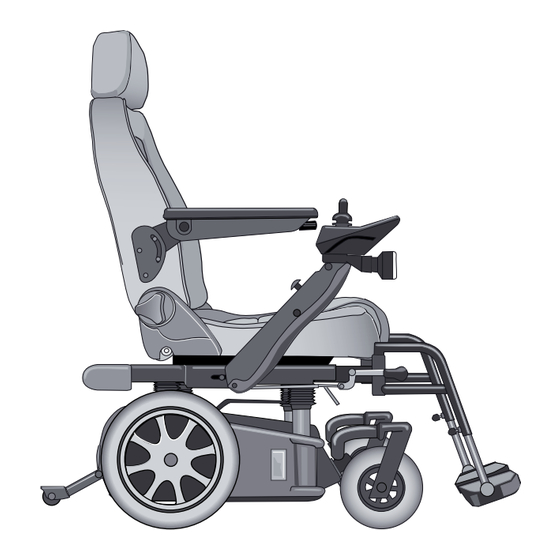
- Page 17 2:1 Description of mechanical system Low and compact The Carony Go/ Drive is a very compact and low electrical wheel chair. It has a height adjusting possibility which will provide the driver optimal height for all opportunities. It is made of steel and powder painted for the rust and impact protec- tion.
- Page 18 2:2 Exploded views and components Carony Go wheel unit...
- Page 19 2:2 Exploded views and components Component list for Carony Go wheel unit Fig. pcs. Description Art.No: Self-cutting screw R6B B6x9.5 Locking nut M6LM - M5 412215 Bracket rear lamp 001070 418098 Locking nut M6LM M4 416646 Screw MC6S M4 x 8...
- Page 20 2:2 Exploded views and components Carony Drive footrest system (DISCONTINUED)
- Page 21 SF-DF-3452-Lesjofors Sliderod 419236 M36-0043 Screw M6x16 410759 ISO 7380 - M6 x 16 Starlock 419240 Det-nr. Antal Benämning Anmärkning Ämne Dim. Konstr Ritad Projekt ä Carony Drive_Right Artikel nr 2008-03-31 419195 Exploded view Autoadapt AB Ritn.nr M36-0034 A Carony Drive...
- Page 22 2:2 Exploded views and components Carony Go foot rest...
- Page 23 2:2 Exploded views and components Component list for Carony Go footrest left Fig. pcs. Description Art.No: Included in fig.6 Foot / heel support 100630 Included in fig 2 Wing screw 412186 Tube fittings Ackurat 22x19 418176 28-32S Footrest left 416562 Holder foot rest weld assy.
- Page 24 2:2 Exploded views and components Carony Go / Drive anti-tip...
- Page 25 2:2 Exploded views and components Component list for Carony Go / Drive anti-tip left Fig. pcs. Description Art.No: Screw MK6S M6 x 12 414079 Spring SF-TF SS1774-04 418180 Washer 6.4x12x1.6 412300 Shaft wheel 60 240 414465 Ø t l o...
- Page 26 2:2 Exploded views and components Carony Go / Drive lever system...
- Page 27 2:2 Exploded views and components Component list for Carony Go / Drive lever system Fig. pcs. Description Art.No: Shims 12x18x0.5 415716 Screw MK6S M6 x 12 414079 Washer 7x35x2 SRKB fzb 417804 Locing nut M6LM - M12 412984 Locking nut M6LM - M8...
- Page 28 2:2 Exploded views and components Carony Go / Drive joystick arm system A-A ( 1 : 2 ) B ( 0,30 : 1 ) 2 2 2...
- Page 29 2:2 Exploded views and components Component list for Carony Go / Drive joystick arm system Fig. pcs. Description Art.No: Conduit entry Berner 6x9.5x1.6 418172 Cable chain E04.07.015.0 418134 Washer 8.4x16x1.6 412332 Screw MK6S M8 x 12 svartkrom 412348 Screw MC6S - M5 x 20...
- Page 30 2:2 Exploded views and components Carony Go / Drive motor release handle left 2 2 2...
- Page 31 2:2 Exploded views and components Component list for Carony Go / Drive motor release handle left Fig. pcs. Description Art.No: Screw MC6S M6x25 412904 Screw MC6S M6 x 10 414971 Nut M6M M5 413084 Plug screw 416007 Locking nut M6LM M6...
- Page 32 2:2 Exploded views and components Carony Go rails...
- Page 33 2:2 Exploded views and components Component list for Carony Go rail left Fig. pcs. Description Art.No: Washer BRB 6,4x12x1,6 FZB 412300 Plate spring 001261 418097 Screw MF6S M6x20 417042 Tension pin FRP 3x12 412585 Ø Slide bearing COB010F/FS-1F 0608 418162 Release handle left weld assy.
- Page 34 2:2 Exploded views and components Carony Go / Drive seat and armrests...
- Page 35 2:2 Exploded views and components Component list for Carony Go / Drive seat and armrests Fig. pcs. Description Art.No: Arm rest left. Inkl. screw and 417847 washer Arm rest right. Inkl. screw and 417846 washer Washer BRB 6.4x16x1.5 FZB 415511...
- Page 36 2:3 Trouble shooter Trouble shooting on Mechanics SYMPTOM MEASURE METHOD Height adjustment does not func- Lift motor: 2:4:10 or11 Check lift motor or all Ketter-pillars. tion, but the lift motor is running. Pillars: 2:4: 6 to 9 Height adjustment is lifting un- Check lift motor or Ketter-pillars Lift motor: 2:4:10 or11 evenly.
- Page 37 Brakes, replace 2:4:4 Transversal release shaft, replace 2:4:5 Docking mechanism Carony Go, replace 2:4:6 Rear Ketter-pillar of Carony Go, replace 2:4:7 Rear Ketter-pillar of Carony Drive, replace 2:4:8 Front Ketter-pillar of Carony Go, replace 2:4:9 Front Ketter-pillar of Carony Drive, replace...
- Page 38 2:4 Repair manual 2:4:1 Replace and service the right side drive motor 1. Place a distance under the chassis. 2. Set the motor release lever in drive position. Remove the hub cap. 3. Remove the wheel nut by using a 17 mm 4.
- Page 39 2:4 Repair manual 8. Unscrew the three screws that fi x the motor by 7. Remove the power module according to 3:4:2 using a 4 mm hexagon key. Remove the batteries: User manual 9. Lift out the motor. 10. If the motor needs to be replaced push out the small pin of the release lever and dismount the spring and the lever.
- Page 40 2:4 Repair manual 2:4:2 Replace and service left side drive motor Follow the instruction acording to 2:4:1 Replacing and servicing the motor on the right side Fig. 1- 7/8. Remove the batteries according to the User Manual. 7. Remove the screw that fi xes the motor release lever and remove the lever.
- Page 41 2:4 Repair manual 10. Lift out the motor and disconnect the contact for the power module. The motor might be diffi cult to remove, it has to be lifted as high up as possible to allow the support towards the bottom of the compartment to run free.
- Page 42 2:4 Repair manual 2:4:3 Replace motor brake plate 1. Dismount the motor according to instructions 2. Unscrew the hexagon screws holding the 2:4:1 and 2:4:2. thrust plate. Remove the thrust plate. Unscrew the two screws of the motor cover and Use a solder pen to heat them before trying to remove the cover.
- Page 43 2:4 Repair manual 2:4:4 Replace transversal release shaft 1. Dismount the ball joint on both sides. (instruc- 2. Unscrew the two M4 screws that fi x the clip tions 2.4.1 fi g. 5 and 6) bearings. 3. Lift out the transversal release shaft. 4.
- Page 44 2:4 Repair manual 2:4:5 Replace docking mechanism (Carony Go) 2. Unhook the wire from the hole. 1. Remove the seat. Take away the plug from the wire hole by using a fl at tool. 4. Dismount the plate spring behind the docking mechanism.
- Page 45 2:4 Repair manual 7. The tension pin. 8. Press out the axle for the cup. 9. Remount in reversed order and make sure to use a new pin. The spring shall be changed every 12 months !
- Page 46 2:4 Repair manual • Rear pillars: Art. No: 417424 2:4:6 Replace REAR Ketter-pillars of Carony Go 1. Remove the seat and pull away the top cover. 2. Put the rails aside and loosen the cable chain. Unscrew the 4 hexagon screws of the Carony rails.
- Page 47 2:4 Repair manual 8. Make sure to get the upper part of the new 7. Pull the pillars slightly outwards unil the hexa- Ketter-pillar facing towards the correct position, gon rod can go free. Cut away the locking clips to fi t the Carony rail when remounting. from the hexagon rod.
- Page 48 2:4 Repair manual • Rear pillars: Art. No: 417424 2:4:7 Replace REAR Ketter-pillar of Carony Drive 2. Remove the nut from the balljoint attachment 1. Remove the seat by unscrewing the 4 screws. for the footrest system. Take away the top cover. Unscrew the one screw holding the joystick arm and put it aside.
- Page 49 2:4 Repair manual 7. Unscrew also the two front screws for the 8. Cut away the bundle band and remove the DriveLOC plate. rubber housing from the Ketter-pillar that is going to be changed. 9. Unscrew the two screws of the lift motor at- 10.
- Page 50 2:4 Repair manual • Front pillars: Art. No: 417423 2:4:8 Replace FRONT Ketter-pillar of Carony Go 1. Remove the seat and pull away the top cover. 2. Put the rails aside and loosen the cable chain. Unscrew the 4 hexagon screws of the Carony rails.
- Page 51 2:4 Repair manual 11. Make sure to get the upper part of the new 12. Be extremely careful to get the same height Ketter-pillar facing towards the correct position, of the new Ketter-pillar, - shall not differ more than to fi t the Carony rail when remounting. 1 mm compared to the others.
- Page 52 2:4 Repair manual 2:4:10 Replace lift motor on Carony Go 1. Remove the seat and pull away the top cover. 2. Put the rails aside and loosen the cable chain. Unscrew the 4 hexagon screws of the Carony rails. 4. Unscrew the two screws holding the Ketter-pil- 3.
- Page 53 Follow the instructions according to 2:4:7 Change of REAR Ketter-pillar of Carony Drive Use the instructions from 1 - 9 Then follow the instructions from pic. 6 through to 8, according to 2: 4:10 Change of Lift motor on Carony Go...
- Page 54 2:4 Repair manual 2:4:12 Replace Joystick arm release lever incl. adjustment and change of gas spring 1. Remove the plastic cover under the joystick 2. Disconnect the cable from the joystick. arm, by fi rst unscrewing the Phillips screw and then the three plastic clips.
- Page 55 2:4 Repair manual 6. Remove the counter nut and unscrew the release head from the gas spring. Screw the new release head onto the gas spring until the head of the pin is in contact with the contact plate. Then screw the gas spring 1 and 3/4 turns further.
- Page 56 2:4 Repair manual 2:4:13 Replace docking mechanism wire. 2. Remove the outer nut of the wire adjustment 1. Use a pair of slim fl at pliers and release the from the rail. end of the wire from the lock head. 3.
- Page 57 2:4 Repair manual 2:4:14 Anti-tip 1. Knock away the A-lock washer on one side and pull out the pin. 2. Protect the handle with a piece of cloth. Remove the handle by unscrewing it, using a pair of universal pliers. 3.
- Page 58 2:4 Repair manual 2:4:15 Replace footrest rails for Carony Drive 1. Unscrew the 4 screws of seat from under- 2. Start by unscrewing the rear screw of the rail neath. Adjust the height of the unit until the rear that needs changing. rail screws are reachable.
- Page 59 2:4 Repair manual 7. This is what has been removed. 8. When remounting, place the weded nuts inside the rail when the rail is in position. Screw in reversed order. Check the function!
- Page 60 2:4 Repair manual 2:4:16 Replace Ketter-pillar bushings 1. Remove the seat: Carony Go: release the seat and remove it..Carony Drive: unscrew the 4 screws from underneath and remove the seat. 2. Carony Drive: Remove the fottrest system unit 3. BE CAREFUL with the cable chain from the from the Ketter-pillars by dismounting the link joystick arm, it can easily be damaged.
- Page 61 2:4 Repair manual 6. Carefully remove the bushing by using a tool. 7. Tap down the new bushing in level with the pipe, by using a plastic hammer. 8. Drill a new hole in the bushing and mount a new pop rivet.
-
Page 63: Control Unit
(fl ash code) ON/OFF button When pressed all battery gauge indicators will light briefl y. Holding it down for four seconds the Carony Go will enter lock mode (to turn the Carony Go on again press the horn button twice). - Page 64 Pressing the button again will turn the lights off. (Optional) INDICATORS To indicate left or right turns. Pressing the button again will make it stop. The Carony Go is equipped with a auto cancel for the indicators wich means that after 10 s the indicators will go off.
- Page 65 3:1 Description and programming Locking and unlocking the control unit The lock function of the control unit is disabled (off) as supplied from the factory. However the programmable feature can be enabled and used to prevent unauthor- ized people from turning it on. To lock the control unit While power is ON, press and hold the power button for 4 seconds.
- Page 66 Drive motor cont. current Drive motor resistance 250mOhm Short Circuit Current Control* * Because there is only one main fuse (50 A) the Carony Go is equipped with a short circuit control system that inhibit current fl ow through circuits if short circuited.
- Page 67 ATTENDANCE DRIVE (Option) The attendance drive makes it possible for the care giver to oper- ate the Carony Go. You can switch between user mode and attendant mode. The speed poten- tiometer adjust the overall speed/response of the chair. Adjust it depending on the speed you...
- Page 68 3:1 Description and programming Programming the control system WARNING: Performance adjustments should only be made by professionals in the health care fi eld or by persons fully conversant with the adjustment process and the user’s capabilities. Incorrect settings, or programming in an unsafe location, could cause injury to the operator or bystanders or damage to property.
- Page 69 Sets how quickly Carony Go/Drive will decelerate when the joystick is Reverse Deceleration moved towards neutral from a reversed position. The maximum speed Carony Go/Drive will turn with the joystick full left or Maximum Turn Speed right and the speed pot fully clockwise.
- Page 70 3:1 Description and programming Settings Description Load Compensation This matches SHARK to the motors. it indicates to SHARK the resistance of the motors so that it can compensate apropriately for adverse driving conditions, for example when going over curbs and ramps. SHARK will not control the chair correctly unless this is set correctly.
- Page 71 3:1 Description and programming Flow Chart, pic. 1...
- Page 72 3:1 Description and programming Flow Chart, pic. 2...
- Page 73 3:1 Description and programming Flow Chart, pic. 3...
- Page 74 3:2 Wiring diagram...
-
Page 76: 3:3 Trouble Shooting
3:3 Trouble shooting Diagnistics Tools Hand Held Programmer Plugging a Hand Held Programmer into the SHARK Remote when an abnormal condition exists will cause the fault to be displayed. A 4-digit code will be displayed which indicates the condi- tion. The fi... - Page 77 fi t together). Electrical system, description The Carony Go has a 24 V electrical system with two 12 V batteries connected in series. Volt- age feed is supplied via a 50 A slow burn main fuse to the power module.
- Page 78 Flashing wrench Flash Codes The Carony Go and Drive is equipped with a self diagnose system which can tell the service technician what kind of problem there is to fi nd. In the control unit there is a wrench which fl...
- Page 79 3:3 Trouble shooting DIAGNOSTICS Code Fault source Sub code Meaning User Out Of Neutral At Power Up (OONAPU) : • Release the joystick to the centre and try again Motor overload (too steep) : • The motor is nort strong enough, try another route Control unit is locked : •...
- Page 80 3:3 Trouble shooting DIAGNOSTICS continuation Code Fault source Sub code Meaning Parkbrake 1 Drive-time test failed : • Check the parkbrake cables. Parkbrake 2 Parbrake not connected or broken : • Check if the cables of the parkbrake are loose. Parkbarek short circuit or broken : •...
- Page 81 3:3 Repair manual 3:4:1 Batteries, replace 3:4:2 Power module, replace 3:4:3 Joystick, dismount 3:4:4 Speedlimiter and height switch, replace...
- Page 82 3:4 Repair manual 3:4:1 Replace batteries IMPORTANT: Both batteries must be replaced at the same time. Always replace batteries of the same type and brand. 1. Remove the cover from the wheel unit. 2. Disconnect the cable contacts and turn the Remove the battery clamp by fi...
- Page 83 3:4 Repair manual 3:4:2 Replace Power module 1. Disconnect the battery contact by the fuse 2. Unscrew the two screws fi xing the power holder. module. 3. Lift up the power module as high as possible 4. Replace the power module and connect all the and disconnect the contacts from the bottom side.
- Page 84 3:4 Repair manual 3:4:3 Dismounting the joystick 1. Fold down the joystick arm and the joystick. 2. Remove the two hexagon screws that hold the impact protection. 4. Replace the joystick with a new and mount this in reversed order. 3.
- Page 85 3:4 Repair manual 3:4:4 Replacing the speed limiter/height switch 2. Remove both the cables from the switch. 1. Remove the seat and the Velcro fastened plas- tic cover. Locate the microswitch. 4. Remove the switch by pulling it out. 3. Unscrew the lock screw with a 2mm Allen wrench, don’t remove it, just loosen it.
- Page 86 Notes...
- Page 87 Notes...
- Page 88 Notes...
- Page 89 Art. No: Not Available Autoadapt Customer Support Centre (CSC) Tel: +46 302 25440 Fax: +46 302 25407 E-mail: support@autoadapt.com Autoadapt AB Åkerivägen 7 S-443 61 Stenkullen Sweden Tel: +46 302 25400 E-mail: contact@autoadapt.com www.autoadapt.com www.autoadapt.de www.autoadapt.fr www.autoadapt.se...
Need help?
Do you have a question about the Carony Go and is the answer not in the manual?
Questions and answers