
Subscribe to Our Youtube Channel
Related Manuals for Raycap 3315-ALM-RS485

Summary of Contents for Raycap 3315-ALM-RS485
- Page 1 3315-ALM-RS485 INSTALL INSTRUCTIONS Installation Instructions: 3315-ALM-RS485 www.raycap.com...
-
Page 3: Table Of Contents
This documentation is intended for the use of Raycap customers only for the purposes of the agreement under which the document is submitted, and no part may be used, reproduced, modified or transmitted in any form or means without the prior written permission of Raycap. -
Page 4: Warnings
Installers of Raycap’s RRH surge protective and fiber/power management solutions must be industry professionals who have attended training on the proper installation of the equipment by Raycap and/or the mobile operator. Installers are required to read this installation guide thoroughly prior to installation of the Raycap RRH protection equipment. -
Page 5: Pre-Wiring Preperation Procedure
Carefully slide the copper dome over the top of the assembly and set aside. To access power, fiber and alarm wire connections, unclasp 1/4 turn latches, then fold down fiber tray. ©Raycap • All rights reserved 320-1261 Rev.C www.raycap.com Page 5 of 24... - Page 6 Voltage Monitor Connection Monitor Connection Sensor Connections Sensor Pass-Thru Connections Alarm Strikesorb Connector Module -48V Alarm Connection Board Return Connection Fiber Connection Fiber Fiber Panel Panel Management Label ©Raycap • All rights reserved 320-1261 Rev.C www.raycap.com Page 6 of 24...
-
Page 7: Removing Strikesorb Modules
Rock the Strikesorb module side to side, and pull it out. Note: You have to overcome a strong spring contact to remove module. ©Raycap • All rights reserved 320-1261 Rev.C www.raycap.com Page 7 of 24... -
Page 8: Removal Of Touch Guard
Remove 7 screws screwdriver, securing the touch guard. Remove touch guard and set aside. Touch guard will not be used for 3315-ALM-RS485 kit installation. Remove Remove the 2 labels from the frame as indicated. Labels ©Raycap • All rights reserved 320-1261 Rev.C... -
Page 9: Removal Of Existing Alarm Wiring
INSTALL INSTRUCTIONS Procedure Removal of Existing Alarm Wiring NOTE – Label each alarming wire to ensure proper connection when reinstalling to 3315-ALM-RS485 PCB. Depress the release tabs on the Intrusion Alarm Intrusion and Power Connectors before pulling on the connector,... -
Page 10: Removal Of Stand-Offs & Alarm Board
Procedure Removal of Stand-Offs and Alarm Board NOTE – Label each alarming wire to ensure proper connection when reinstalling to 3315-ALM-RS485 PCB. Remove 7 stand-offs Using a ¼” nut-driver, securing the PCB to the frame. Remove PCB and set aside. -
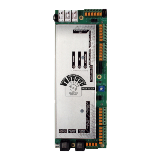
Page 11: Installation Of 3315-Alm-Rs485
F. Base Communication: Base RS485 communication input from tower, 2-twisted pair (4 wires total) G. VBoost Input: Optional ethernet daisy chain input H. VBoost Output: Optional ethernet output to daisy chain / VBoost ©Raycap • All rights reserved 320-1261 Rev.C www.raycap.com Page 11 of 24... - Page 12 3315-ALM-RS485 INSTALL INSTRUCTIONS Procedure Installation of 3315-ALM-RS485 (continued) 10.2 The power wire is secured to frame. In order for the power wire to reach the connection terminal, the cable tie must be clipped. 10.3 From the backside of the unit, carefully...
- Page 13 3315-ALM-RS485 INSTALL INSTRUCTIONS Procedure Connecting wires to 3315-ALM-RS485 10.4 Connect the Power Intrusion and H O wires. Intrusion Alarm Power Water Ingress Alarm ©Raycap • All rights reserved 320-1261 Rev.C www.raycap.com Page 13 of 24...
- Page 14 3315-ALM-RS485 INSTALL INSTRUCTIONS 11.1 Alarm connections for 3315-ALM-RS485 RVZDC-3315-PF-48 at the Tower Top connected to RVZDC-3315-PF-48 with Retrofit Kit at the base. Voltage Monitoring on Main PCB Pair Color Alarm Input Yellow RTN (1) Black -48V (1) RTN (2) Black...
- Page 15 3315-ALM-RS485 INSTALL INSTRUCTIONS Alarm Board 3315 Tower Top Unit Pair Color Alarm Input Black -48V Black/White Orange INTR Black Violet Black ©Raycap • All rights reserved 320-1261 Rev.C www.raycap.com Page 15 of 24...
- Page 16 3315-ALM-RS485 INSTALL INSTRUCTIONS Alarm connections for 3315-ALM-RS485 11.2 RVZDC-6627-PF-48 at the Tower Top connected to (2) RVZDC-3315-PF-48 with Retrofit Kits at the base. Tower Alarm Outputs to BTS Base “1” Note: Base Mode Address “1” Position “3” ©Raycap • All rights reserved 320-1261 Rev.C...
- Page 17 3315-ALM-RS485 INSTALL INSTRUCTIONS Pair Color Data Black White/Black Orange REF2 Orange/Black REF2 Violet Violet/Black Yellow REF1 Yellow/Black REF1 Base “0” Note: Base Mode Address “0” Position “2” ©Raycap • All rights reserved 320-1261 Rev.C www.raycap.com Page 17 of 24...
- Page 18 3315-ALM-RS485 INSTALL INSTRUCTIONS Alarm connections for 3315-ALM-RS485. 11.3 Third Generation RVZDC-3315-PF-48 installed on Tower Top. -48V -48V RTN -48V -48V -48V RTN -48V Note: Set to “1” for Tower Top Mode Operation Outputs to Base ©Raycap • All rights reserved 320-1261 Rev.C...
- Page 19 3315-ALM-RS485 INSTALL INSTRUCTIONS Alarm connections for 3315-ALM-RS485. 11.4 Second Generation RVZDC-3315-PF-48 installed on Tower Top. Note: Set to “1” for Tower Top Mode Operation Outputs to Base ©Raycap • All rights reserved 320-1261 Rev.C www.raycap.com Page 19 of 24...
- Page 20 Slide enclosure lid into place. 13.2 As pictured, Lid IS NOT properly aligned. Red must be completely covered for proper lid alignment. 13.3 As pictured, Lid IS properly aligned. ©Raycap • All rights reserved 320-1261 Rev.C www.raycap.com Page 20 of 24...
-
Page 21: Installing Complete
Note: If padlock holes are NOT aligned, the lid is NOT properly aligned. 13.5 When alignment of lid is comfirmed, close and secure all clamps. Installation complete. ©Raycap • All rights reserved 320-1261 Rev.C www.raycap.com Page 21 of 24... -
Page 22: 14. Supported Configurations
6627 “4520” = 12 OVP Rack | “2260” = 6 OVP Rack | “6627” = 12 OVP Dome | “3315” = 6 OVP Dome “with Retrofit” = Retrofit Alarm Board installed ©Raycap • All rights reserved 320-1261 Rev.C www.raycap.com Page 22 of 24... -
Page 24: Raycap • All Rights Reserved 320-1261 Rev.c
3315-ALM-RS485 INSTALL INSTRUCTIONS ©Raycap • All rights reserved 320-1261 Rev.C www.raycap.com Page 24 of 24...
Need help?
Do you have a question about the 3315-ALM-RS485 and is the answer not in the manual?
Questions and answers