
Related Manuals for Raycap 2260-ALM-RS485

Summary of Contents for Raycap 2260-ALM-RS485
- Page 1 2260-ALM-RS485 INSTALL INSTRUCTIONS Installation Instructions: 2260-ALM-RS485 www.raycap.com...
-
Page 3: Table Of Contents
This documentation is intended for the use of Raycap customers only for the purposes of the agreement under which the document is submitted, and no part may be used, reproduced, modified or transmitted in any form or means without the prior written permission of Raycap. -
Page 4: Introduction
Installers of Raycap’s RRH surge protective and fiber/power management solutions must be industry professionals who have attended training on the proper installation of the equipment by Raycap and/or the mobile operator. Installers are required to read this installation guide thoroughly prior to installation of the Raycap RRH protection equipment. -
Page 5: Removal Of Existing Pcb Board
Make note of each cable connection to ensure proper connections are established when reinstalling -48V, Return, and Ground cables. Remove -48V, Return, and Ground cables from ALL terminals. -48V Return Ground ©Raycap • All rights reserved 320-1254 Rev.C www.raycap.com Page 5 of 24... - Page 6 2260-ALM-RS485 INSTALL INSTRUCTIONS To remove touch guard to access PCB terminals, remove the 4 white plastic screws and set aside. This touch guard will not be used when installing the 2260-ALM-RS485 kit. Touch Guard (over PCB) Make note of each wire connection to ensure proper connections are established when reinstalling alarm wires.
- Page 7 PCB and set aside. Slide PCB down to disconnect from front-PCB. Disconnect ribbon cable from PCB. 4.10 Remove PCB and set aside. This will not be reused. ©Raycap • All rights reserved 320-1254 Rev.C www.raycap.com Page 7 of 24...
-
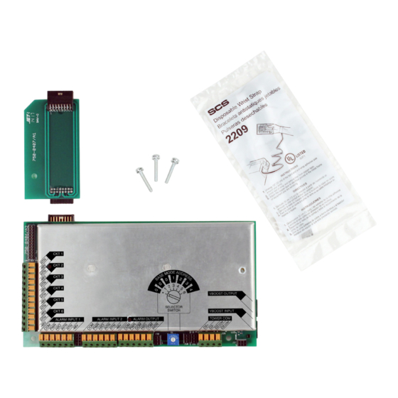
Page 8: Installing The Pcb Retrofit Kit
2260-ALM-RS485 INSTALL INSTRUCTIONS Procedure Installing the PCB Retrofit Kit Remove Alarm Inputs label from unit. The next step will mate the intermediate PCB to a blind connection in this location. ©Raycap • All rights reserved 320-1254 Rev.C www.raycap.com Page 8 of 24... - Page 9 (new shrouded connecter aides in blind connection) PCB Installation Orientation Connector up Chamfer Screw hole Reassemble unit with new PCB as follows: Secure the intermediate PCB using the 1 small screw. ©Raycap • All rights reserved 320-1254 Rev.C www.raycap.com Page 9 of 24...
- Page 10 2260-ALM-RS485 INSTALL INSTRUCTIONS Connect main PCB to intermediate PCB. Ensure 2260-ALM-RS485 PCB is Correctly Aligned (see below) and fully seated. Correctly Aligned Incorrectly Aligned Incorrectly Aligned ©Raycap • All rights reserved 320-1254 Rev.C www.raycap.com Page 10 of 24...
- Page 11 “reuse” 2 small screws. Install the 3 long screws to secure PCB. Reattach ribbon cable to new PCB. Red stripe should be closest to the CKT 1 return connector. ©Raycap • All rights reserved 320-1254 Rev.C www.raycap.com Page 11 of 24...
-
Page 12: Installation Complete
2260-ALM-RS485 INSTALL INSTRUCTIONS Installation Complete ©Raycap • All rights reserved 320-1254 Rev.C www.raycap.com Page 12 of 24... -
Page 13: Installing Alarm Wiring
F. Base Communication: Base RS485 communication input from tower, 2-twisted pair (4 wires total) G. VBoost Input: Optional ethernet daisy chain input H. VBoost Output: Optional ethernet output to daisy chain / VBoost ©Raycap • All rights reserved 320-1254 Rev.C www.raycap.com Page 13 of 24... - Page 14 Tower Note: Selector switch set to “•” or ”1” for Tower Top mode Pair Color Data Black White/Black Orange REF2 Orange/Black REF2 Violet Violet/Black Yellow REF1 Yellow/Black REF1 ©Raycap • All rights reserved 320-1254 Rev.C www.raycap.com Page 14 of 24...
- Page 15 “0” Base “1” Daisy Chain Output to next Base unit Daisy Chain Input Note: Selector switch set to Alarm “3” for Base mode Outputs address “1” to BTS ©Raycap • All rights reserved 320-1254 Rev.C www.raycap.com Page 15 of 24...
- Page 16 -48V (4) Brown RTN (5) Black -48V (5) White RTN (6) White/Black -48V (6) PCB TERMINAL BLOCK DISTRIBUTION UNIT PCB TERMINAL BLOCK PASS-THRU PASS-THRU CIRCUITS 1-3 CIRCUITS 4-6 ©Raycap • All rights reserved 320-1254 Rev.C www.raycap.com Page 16 of 24...
- Page 17 INSTALL INSTRUCTIONS 7.3 Voltage Monitoring Connections for 2260-ALM-RS485 Wiring scenario for RVZDC-3315-PF-48 at tower top connected to RVZDC-2260-RM-48 with a retrofit kit at the base. Tower Top Alram Wiring Diagram. These instructions are for interconnecting the alarms for the Raycap products. (Voltage monitoring circuit on previous page) Wire the alarms using the Verizon approved color code. Pair Color Alarm Input...
- Page 18 2260-ALM-RS485 INSTALL INSTRUCTIONS 7.4 Meaning of signal lights Right and left center bars flashing- bootloader mode. Lower left bar flashing- reciept & varification of daisy chain data. ©Raycap • All rights reserved 320-1254 Rev.C www.raycap.com Page 18 of 24...
- Page 19 2260-ALM-RS485 INSTALL INSTRUCTIONS Lower right bar flashing- reciept and varification of tower data. Upper right bar flashing- Analog packet generated at base. ©Raycap • All rights reserved 320-1254 Rev.C www.raycap.com Page 19 of 24...
-
Page 20: 8. Supported Configurations
6627 “4520” = 12 OVP Rack | “2260” = 6 OVP Rack | “6627” = 12 OVP Dome | “3315” = 6 OVP Dome “with Retrofit” = Retrofit Alarm Board installed ©Raycap • All rights reserved 320-1254 Rev.C www.raycap.com Page 20 of 24... - Page 21 2260-ALM-RS485 INSTALL INSTRUCTIONS Notes ©Raycap • All rights reserved 320-1254 Rev.C www.raycap.com Page 21 of 24...
- Page 22 2260-ALM-RS485 INSTALL INSTRUCTIONS Notes ©Raycap • All rights reserved 320-1254 Rev.C www.raycap.com Page 22 of 24...
- Page 24 2260-ALM-RS485 INSTALL INSTRUCTIONS ©Raycap • All rights reserved 320-1254 Rev.C www.raycap.com Page 24 of 24...
Need help?
Do you have a question about the 2260-ALM-RS485 and is the answer not in the manual?
Questions and answers