
Related Manuals for Daikin Templifier TGZ


Summary of Contents for Daikin Templifier TGZ
- Page 1 Installation and Maintenance Manual IM 1137-4 Group: Chiller Part Number: IM1137-4 Templifier ® Date: June 2018 Heat Recovery Water Heaters Supersedes: July 2017 Model TGZ, B Vintage 600 to 3100 MBH HFC-134a Refrigerant 60/50 Hz...
-
Page 2: Table Of Contents
Manufactured in an ISO 9001 & ISO 14001 certified facility ©2018 Daikin Applied. Illustrations and data cover the Daikin Applied product at the time of publication and we reserve the right to make changes in design and construction at any time without notice. - Page 3 Document Attached: Remote piping approval Notes: The most common problems delaying start-up and affecting unit reliability are: Field installed compressor motor power supply leads too small. Questions: Contact the local Daikin sales representative*. State size, number and type of conductors and conduits installed: From Power supply to chiller * Refer to NFPA 70-2017, Article 440.35...
-
Page 5: Introduction
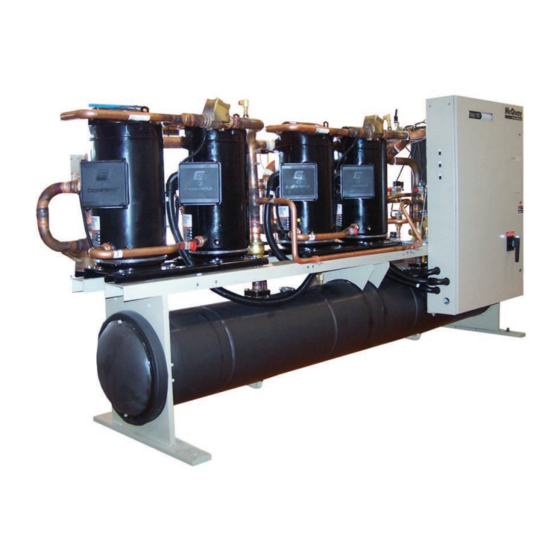
General Description Daikin TGZ water heaters are scroll compressor refrigeration units that recover heat from warm fluid streams in the evaporator and deliver hot water, at a useful temperature, from the condenser to a heating load. They are designed for indoor installations only and are completely assembled, wired, charged and tested. -
Page 6: Installation
Do not attach slings to piping or equipment. Move unit in the Daikin Applied. upright horizontal position at all times. Set unit down gently NOTE: Unit shipping and operating weights are given in the when lowering from the trucks or rollers. - Page 7 nsTallaTIon Once the unit has been located, set the unit in place and level on page 24 for correct lifting and mounting locations. with a spirit level. When spring-type isolators are required, Installation of spring isolators requires flexible piping install springs running under the main unit supports. connections and at least three feet of flexible electrical conduit The unit should be set initially on shims or blocks at the listed to avoid straining the piping and transmitting vibration and...
- Page 8 nsTallaTIon NOTE: Refer to Figure 2 on page 6 for locating isolators. NOTE: For spring-flex mountings, CP2E have two springs per isolator housing, CP1E have one spring per housing. Figure 3: Spring Flex Mounting (CP-1) Isolator Dimensions Figure 5: Rubber-in-Shear Mounting (RP-3) Isolator Dimensions Figure 4: Spring Flex Mounting (CP-2) Isolator Dimensions Figure 6: Rubber-in-Sheer Mounting (RP-4) Isolater...
- Page 9 nsTallaTIon Chilled Water Piping connection pipe, respectively. See Figure 7. These evaporators do not have drain or vent connections due to their construction. CAUTION • Purge air from the water system before unit start-up to To prevent damage to the evaporator and potential chiller provide adequate flow through the evaporator.
- Page 10 nsTallaTIon Figure 8: Typical Piping for Shell and Tube Evaporator VENT LEAVING FLUID 3/8” PIPE PLUG TEMP. SENSOR OUTLET VIBRATION ELIMINATOR FLOW INLET SWITCH VALVED PRESSURE GAUGE GATE VALVE VIBRATION BALANCING ELIMINATOR VALVE DRAIN GATE WATER FLOW VALVE STRAINER PROTECT ALL FIELD PIPING AGAINST FREEZING WELDED PIPE CONNECTIONS ARE NOT ALLOWED FLOW...
- Page 11 Stainless Steel, Copper Carbon Steel, Copper guard against evaporator freeze-up. Max Perf. Size No larger than 0.062” dia. No larger than 0.125” dia. A flow switch is available from Daikin Applied (part # Cleaning Chemical Chemical 01750330). It is a “paddle” type switch and adaptable to any pipe size from 1”...
- Page 12 Obtain percent glycol from the freezing point table below. Daikin Applied encourages a minimum glycol concentration of 25% be provided on all glycol applications. Glycol concentrations below 25% have too little inhibitor content for long-term corrosion protection of ferrous metals.
- Page 13 nsTallaTIon Table 7: Relief Valve Piping CAUTION Do not use automotive grade antifreeze. Industrial grade Suction Line Cond. Shell 30 HP Disch. Total per TGZ Model Size glycols must be used. Automotive antifreeze contains Total Total Line Total Unit inhibitors which will cause plating on the copper within the unit evaporator.
- Page 14 nsTallaTIon Water Pressure Drop Figure 11: Relief Valve Piping The vessel flow rates must fall between the minimum and maximum values shown on the appropriate evaporator and condenser curves beginning on page 16. Flow rates below the minimum values shown will result in laminar flow that will reduce efficiency, cause erratic operation of the expansion valve, and could cause low temperature cutoffs.
-
Page 15: Piping Schematic
IPIng ChemaTIC IPIng ChemaTIC Figure 12: Piping Schematic, Models TGZ 040 – 120 Figure 13: Piping Schematic, Models TGZ 150 – 190 www.DaikinApplied.com IM 1137-4 • TEMPLIFIER MODEL TGZ ®... -
Page 16: Pressure Drop Data
ressure ressure Figure 14: Evaporator Pressure Drop TGZ040 TGZ050 TGZ060 TGZ080 TGZ190 TGZ100 TGZ110 TGZ170 TGZ120 TGZ120 TGZ110 TGZ100 TGZ150 TGZ150 TGZ170 TGZ080 TGZ190 TGZ050 TGZ060 TGZ040 TGZ190 TGZ170 TGZ120 TGZ110 TGZ100 TGZ150 TGZ080 TGZ040 TGZ050 TGZ060 1000 Flow Rate (gpm) Table 9: Evaporator Pressure Drop Minimum Flow Rate Nominal Flow Rate... - Page 17 ressure Figure 15: Standard Four-pass Condenser Pressure Drop Table 10: Standard Four-pass Condenser Pressure Drop Minimum Flow Rate Nominal Flow Rate Maximum Flow Rate UNIT COND. Inch-Pound S .I . Inch-Pound S .I . Inch-Pound S .I . MODEL MODEL DP ft DP kpa DP ft...
- Page 18 ressure Figure 16: Optional Two-pass Condenser Table 11: Optional Two-pass Condenser Minimum Flow Rate Nominal Flow Rate Maximum Flow Rate TGZ UNIT COND. Inch-Pound S .I . Inch-Pound S .I . Inch-Pound S .I . MODEL MODEL DP ft DP kpa DP ft DP kpa DP ft...
-
Page 19: Dimensional Drawings
ImensIonal rawIngs ImensIonal rawIngs Figure 17: Dimensions, TGZ040B – TGZ060B, Standard 4-pass Condenser NOTE: See “Weights” on Table 12 on page 24 for lifting and corner weights. Left-hand condenser connections are an available option. www.DaikinApplied.com IM 1137-4 • TEMPLIFIER MODEL TGZ ®... - Page 20 ImensIonal rawIngs Figure 18: Dimensions, TGZ080B – TGZ100B, Standard 4-Pass Condenser NOTE: See “Weights” on Table 12 on page 24 for lifting and corner weights. Left-hand condenser connections are an available option. IM 1137-4 • TEMPLIFIER MODEL TGZ www.DaikinApplied.com ®...
- Page 21 ImensIonal rawIngs Figure 19: Dimensions, TGZ110B – TGZ120B, Standard 4-Pass Condenser NOTE: See “Weights” on Table 12 on page 24 for lifting and corner weights. Left-hand condenser connections are an available option. www.DaikinApplied.com IM 1137-4 • TEMPLIFIER MODEL TGZ ®...
- Page 22 ImensIonal rawIngs Figure 20: Dimensions, TGZ150B –TGZ190B, Standard 4-Pass Condenser NOTE: See “Weights” on Table 12 on page 24 for lifting and corner weights. Left-hand condenser connections are an available option. IM 1137-4 • TEMPLIFIER MODEL TGZ www.DaikinApplied.com ®...
- Page 23 ImensIonal rawIngs NOTE: For optional left-hand connections, reverse the images below. Figure 21: Dimensions, TGZ040B – TGZ060B, Optional 2-Pass condenser Figure 22: Dimensions, TGZ080B –TGZ100B, Optional 2-Pass Condenser Figure 23: Dimensions, TGZ110B – TGZ120B, Optional 2-Pass Condenser Figure 24: Dimensions, TGZ150B – TGZ190B, Optional 2-Pass Condenser NOTE: Tube sheet-to-tube sheet dimensions are the same for a 4-pass condenser.
- Page 24 ImensIonal rawIngs Weights NOTE: Refer to Figure 25 for lifting and mounting point’s physical location. Table 12: TGZ Lifting, Mounting, and Total Weights, Inch-Lbs Units Table 13: TGZ Lifting, Mounting, and Total Weights, SI Units Figure 25: Lifting and Mounting Points Location IM 1137-4 •...
-
Page 25: Physical Data
hysICal hysICal Table 14: TGZ 040B – 060B TGZ Unit Model TGZ040B TGZ050B TGZ060B No. Of Circuits COMPRESSORS (4) Nominal Horsepower Number per Circuit Unloading Steps, % 25 / 50 / 75 100 25 / 50 / 75 100 25 / 50 / 75 100 Oil Charge, per compr. - Page 26 hysICal Table 15: TGZ080B – 100B TGZ Unit Model TGZ080B TGZ100B No. Of Circuits COMPRESSORS (2) Nominal Horsepower Number per Circuit Unloading Steps, % 25 / 50 / 75 100 25 / 50 / 75 100 Oil Charge, per compr. Oz (l) 158 (4.7) 200 (5.9) CONDENSER...
- Page 27 hysICal Table 16: TGZ 110B – 120B TGZ Unit Model TGZ110B TGZ120B No. Of Circuits COMPRESSORS (2) Nominal Horsepower Number per Circuit Staging, 4 Stages, Circuit #1 in Lead 23/50/73/100 25 / 50 / 75 100 Staging, 4 Stages, Circuit #2 in Lead 27/50/77/100 25 / 50 / 75 100 Oil Charge, per compr.
- Page 28 hysICal Table 17: TGZ 150B – 190B TGZ Unit Model TGZ150B TGZ170B TGZ190B No. Of Circuits COMPRESSORS (2) Nominal Horsepower Number per Circuit Staging, 6 Stages, Circuit #1 in Lead 17 / 33 / 50 / 67 / 83 /100 15 / 33 / 48 / 67 / 81 / 100 17 / 33 / 50 / 67 / 83 /100 Staging, 6 Stages, Circuit #2 in Lead 17 / 33 / 50 / 67 / 83 /100 19 / 34 / 52 / 67 / 85 / 100 17 / 33 / 50 / 67 / 83 /100 Oil Charge, per compr.
-
Page 29: Eletrical Data
leTrICal leTrICal Unit Components Figure 26: Compressor Locations NOTE: Models TGZ150 to TGZ190 add a #5 compressor to circuit #1 and a #6 compressor to circuit #2 and substitute an underslung shell- and-tube evaporator for the brazed-plate evaporator. Figure 27: Electric Panel Components NOTE: Models TGZ 150 –... - Page 30 leTrICal Electrical Notes Voltage Limitations 1. Within +/- 10% of nameplate rating Field Wiring 2. Voltage unbalance not to exceed 2% with a resultant current The TGZ units are supplied as standard with compressor contactors unbalance of 6 to 10 times the voltage unbalance per NEMA MG-1 and power terminal block, designed for multi-point power supply to the Standard.
- Page 31 leTrICal Circuit Breakers The circuit breaker used in the High Short Circuit panel option may have a higher trip rating than the unit Maximum Overload Protection (MOP) value shown on the unit nameplate. The circuit breaker is installed as a service disconnect switch and does not function as branch circuit protection, mainly that the protection device must be installed at the point of origin of the power wiring.
- Page 32 leTrICal Table 20: RLA-LRA Model Voltage Compressors RLA with Overload Compressors RLA without Overload Compressors LRA Size Size 30.8 30.8 30.8 30.8 35.3 35.3 35.3 35.3 28.0 28.0 28.0 28.0 35.3 35.3 35.3 35.3 040B 16.8 16.8 16.8 16.8 21.2 21.2 21.2 21.2...
- Page 33 leTrICal Table 21: Single Point with External Overloads Model Voltage Field Wire Max. Power Block [2] Disconnect Switch [2] Size Size Wire GA Size Lug Range Size Lug Range 1/0 AWG 175A (1) 2/0 - #14 250A (1) 350 - #6 1 AWG 175A (1) 2/0 - #14...
- Page 34 leTrICal Table 22: Single Point without External Overloads Model Voltage Field Wire Max. Power Block [2] Disconnect Switch [2] Size Size Wire GA Size Lug Range Size Lug Range 1/0 AWG 380A (1) 500 - #4 250A (1) 350 - #6 1/0 AWG 380A (1) 500 - #4...
- Page 35 leTrICal Table 23: Multi-Point with External Overloads Model Voltage Cir #1 Field Wire Max. Cir #2 Field Wire Max. Size Size Wire GA Wire GA 4 AWG 4 AWG 6 AWG 6 AWG 040B 8 AWG 8 AWG 460/400 60/50 10 AWG 10 AWG 10 AWG...
- Page 36 leTrICal Table 24: Multi-Point with External Overloads Cir #1 Power Block [2] Cir #1 Disconnect Sw [2] Cir #2 Power Block [2] Cir #2 Disconnect Sw [2] Model Voltage Size Size Size Lug Range Size Lug Range Size Lug Range Size Lug Range 175A...
- Page 37 leTrICal Table 25: Multi-Point without External Overloads Model Voltage Cir #1 Field Wire Max. Cir #2 Field Wire Max. Size Size Wire GA Wire GA 4 AWG 4 AWG 4 AWG 4 AWG 040B 8 AWG 8 AWG 460/400 60/50 8 AWG 8 AWG 10 AWG...
- Page 38 leTrICal Table 26: Multi-Point without External Overloads Model Voltage Cir #1 Power Block [2] Cir #1 Disconnect Sw [2] Cir #2 Power Block [2] Cir #2 Disconnect Sw [2] Size Size Size Lug Range Size Lug Range Size Lug Range Size Lug Range 175A...
-
Page 39: Start-Up And Shutdown
12. Make sure all wiring and fuses are of the proper size. Also 4. Check circuit breakers. They must be in the “off” position. make sure all interlock wiring is completed per Daikin Applied 5. Check to see that the pumpdown switch(es) PS1 and PS2 diagrams. - Page 40 (e.g. PVC/CPVC and polycarbonate piping). every six months, as they tend to loosen in service due to Daikin Applied recommends against the use of PVC and normal heating and cooling of the wire. CPVC piping for chilled water systems. In the event the pipe...
- Page 41 TarT P and huTdown Table 27: TGZ Temperature Limits Min . Cooling Cycle Temp Temp Note: Evaporator Leaving Water Temp. 60° F In Cooling Cycle controlling Evap LWT - The Maximum Setpoint temp is 60°F 40° F Condenser Leaving Water Temp 70°...
-
Page 42: System Maintenance
ysTem aInTenanCe ysTem aInTenanCe Table 29: Troubleshooting Chart IM 1137-4 • TEMPLIFIER MODEL TGZ www.DaikinApplied.com ®... - Page 43 ysTem aInTenanCe Table 30: Maintenance Schedule www.DaikinApplied.com IM 1137-4 • TEMPLIFIER MODEL TGZ ®...
- Page 44 Now that you have made an investment in modern, efficient Daikin Applied equipment, its care should be a high priority. For training information on all Daikin Applied HVAC products, please visit us at www.DaikinApplied.com and click on Training, or call 540-248-9646 and ask for the Training Department.
Need help?
Do you have a question about the Templifier TGZ and is the answer not in the manual?
Questions and answers