Bakers Pride EP-2-2828 Installation And Operating Instructions Manual
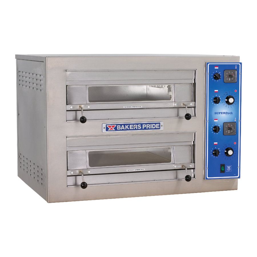
Countertop model electric pizza oven
Hide thumbs
Also See for EP-2-2828:
- Installation and operating instructions manual (17 pages) ,
- Specification (2 pages) ,
- Catalog (72 pages)
Table of Contents
Advertisement
INSTALLATION AND OPERATING INSTRUCTIONS
COUNTERTOP MODEL
ELECTRIC PIZZA OVEN
OVEN MUST BE KEPT CLEAR OF COMBUSTIBLES AT ALL TIMES
For Your Safety: Do not store or use flammable liquids or vapors in the vicinity of this
!
or any other appliance.
Warning: Improper installation, adjustment, alteration, service or maintenance can
!
cause property damage, injury or death.
Maintenance instructions thoroughly before installing or servicing this equipment.
Initial heating of this oven may generate smoke or fumes and must be done in a well ventilated area.
Overexposure to smoke or fumes may cause nausea or dizziness.
This equipment has been engineered to provide you with year round dependable service when used
according to the instructions in thismanual and standard commercial kitchen practices.
+1 (914) 576-0200 Phone
+1 (914) 576-0605 Fax
EP-2-2828
Model:
INTENDED FOR OTHER THAN HOUSEHOLD USE
RETAIN THIS MANUAL FOR FUTURE REFERENCE
BAKERS PRIDE OVEN CO., INC.
30 Pine Street
New Rochelle, NY 10801
Read the Installation, Operating and
www.bakerspride.com WebAddress
1
ANSI/NSF4
Form #U4186A 5/05
(800) 431-2745 US & Canada
info@bakerspride.com e-mail
!
!
Advertisement
Table of Contents

Related Manuals for Bakers Pride EP-2-2828


Summary of Contents for Bakers Pride EP-2-2828
- Page 1 Maintenance instructions thoroughly before installing or servicing this equipment. Initial heating of this oven may generate smoke or fumes and must be done in a well ventilated area. Overexposure to smoke or fumes may cause nausea or dizziness.
-
Page 2: Table Of Contents
(including the prefix and suffix letters and numbers and the warranty serial number. The rating plate affixed to the oven contains this information. -
Page 3: Dimensions & Specifications
Amperes 208-1 208-3 230-1 240-1 240-3 400-3 Interior Dimensions Single 5.25 Double NOTE: Each oven requires its own supply connection to mains. Ovens are shipped individually. 33.25” (845mm) 5.25” (133mm) 2.5” (64mm) Exterior Dimensions 28” (711mm) 29” (737mm) Nominal Amperes... -
Page 4: Installation
It is the responsibility of the purchaser to insure the oven is properly installed in a manner that meets all applicable codes. In the absence of local codes refer to applicable national codes. In the case of any discrepancy between this document and any local codes it is recommended you consult your local inspector. -
Page 5: Optional Open Base Feature
Turn the oven over onto its left side so you can easily reach the boltmounting locations in the base. The three holes in the top of each leg will match the bolt locations at each corner of the oven base. -
Page 6: Double Stacked Ovens
Caution: Disconnect all ovens from electrical supply before servicing. A wiring diagram is affixed to the inner side cover of the oven and included in the rear of this booklet. The input connection is accessed be removing the right side cover. Field connections are located at the lower rear corner of the control compartment. -
Page 7: Explanation Of Controls
Each cavity has top and bottom infinite control switches. Turning the dial of the infinite control to “0” will turn off the heat for that portion of the oven cavity. The proportion of heat decreases as the dial is adjusted from a maximum of “10” to a minimum of “1”. -
Page 8: Usage Recommendations
Each cavity has a timer that may be used when cooking product. The timer DOES NOT control the oven. To set a cook time turn the dial clock wise to the desired setting. The timer will count down until the time expires. -
Page 9: Cleaning
Caution: Disconnect all ovens from electrical supply before servicing. When the oven is new, operate it for at least one hour at a setting of at least 500°F (250ºC). Due to normal manufacturing processes, a small amount of steam and/or smoke will exit the oven from moisture and oils on the oven components. -
Page 10: Parts Lists & Exploded Views
9. PARTS LISTS & EXPLODED VIEWS EP-2-2828 ITEM PART NO DESCRIPTION L1194X Upper Element - 230V 500W Upper Element - 208V 500W L1197X L1200X Upper Element - 240V 500W L1193X Lower Element - 230V 750W L1196X Lower Element - 208V 750W... - Page 11 FIGURE 1 MAIN BODY DOORS SEE FIG 2 CONTROL PANEL SEE FIG 3 FIGURE 2 DOORS DOOR HARDWARE SEE FIG 4 FIGURE 3 CONTROL PANEL ELECTRICAL COMPONENTS SEE FIG 5...
- Page 12 FIGURE 4 DOOR HARDWARE ITEM PART NO DESCRIPTION P1018X Snap Bushing C4075X Spring Adjustment Bracket S3007X Spring Bushing S3004X Spring Q3019X Washer Q2301X Shoulder Bolt C5056X Door Stop Bracket Q2111X 1/4-20 Hex Bolt Q2001X 1/4-20 Hex Nut C5027X Door Stop Bracket FIGURE 5 ELECTRIC COMPONENTS ITEM PART NO...
-
Page 16: Warranty
Damage in shipment, Alteration, misuse or improper installation, Thermostats and safety valves with broken capillary tubes, Accessories — spatulas, forks, steak turners, grate lifters, oven brushes, scrapers, peels, etc., Freight — other than normal UPS charges, Ordinary wear and tear. for all...
Need help?
Do you have a question about the EP-2-2828 and is the answer not in the manual?
Questions and answers