Table of Contents
Advertisement
Advertisement
Table of Contents

Related Manuals for Ryobi RGN2500B


Summary of Contents for Ryobi RGN2500B
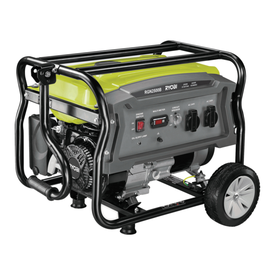
- Page 1 ORIGINAL INSTRUCTIONS Low-Power Generating Set RGN2500B...
- Page 2 Important! It is essential that you read the instructions in this manual before assembling, operating, and maintaining the product. Subject to technical modification.
-
Page 3: Know Your Product
KNOW YOUR PRODUCT 1. Carburetor drain screw 16. To start (choke closed) 2. Oil drainage plug 17. To run (choke open) 3. Oil cap/dipstick 18. Screw 4. Circuit breaker 19. Spark plug 5. Frame handle 20. Spark plug cap 6. Recoil starter grip 21. - Page 4 Fig 4 Fig 5 Fig 6 Fig 7 Fig 8...
- Page 5 Fig 9 Fig 10 Fig 11 Fig 12...
- Page 6 Fig 13 Fig 14 Fig 15 Fig 16 Fig 17...
- Page 7 ENGINE CIRCUIT MULTI METER AC 240V AC 240V SWITCH BREAKER OIL ALERT LAMP Fig 18 CONTROL PANEL LABEL See figure 18. 1. Multimeter 2. Circuit breaker 3. AC receptacle 4. AC receptacle 5. PE Terminal 6. Oil alert lamp 7. Engine switch (off) 8.
-
Page 8: Intended Use
English | Original instructions Safety, performance, and dependability have been given Save these instructions. top priority in the design of your low-power generating set. This manual contains important instructions that should be followed during the installation and maintenance of the INTENDED USE product. -
Page 9: Specific Safety Warnings
Original instructions | English and follow instructions in the Maintenance section of tank cap when the engine is running. Covering the fuel this manual. Use of unauthorised parts or failure to tank cap during use may cause engine failure and/or follow Maintenance instructions may create a risk of damage to the product. -
Page 10: Symbols On The Product
English | Original instructions WARNING To reduce the risk of injury or damage, avoid contact with any hot Service and maintenance require extreme care and surface. service technician. For service and repair, contact an Consult with local electrician authorised service centre. When servicing, use only determine grounding original manufacturer’s replacement parts, accessories,... -
Page 11: Safety Labels
Original instructions | English CAUTION level should always register within the hatched area on the dipstick. The product is equipped with an oil sensor which Without safety alert symbol will automatically shut off the engine if oil level falls below Indicates a situation that may result in property damage. - Page 12 English | Original instructions there may be a risk of explosion of petrol fumes, leaking gas or explosive dusts. 6. Electrocution can occur if generator is used in rain, snow, or near water; keep this unit dry at all times. 7.
-
Page 13: Power Management
Original instructions | English 5. Again, permit the generator to stabilise. ELECTRICAL 6. Repeat steps 4 and 5 for each additional load. 7. Never add more loads than the generator capacity. GENERATOR CAPACITY Take special care to consider surge loads in generator Make sure the generator can supply enough continuous capacity as previously described. - Page 14 English | Original instructions AIR FILTER Inspect the product carefully to make sure no damage occurred during shipping. Do not discard the packing material until you have into the product during operation. carefully inspected and satisfactorily operated the CHOKE LEVER product.
-
Page 15: Operation
Original instructions | English NOTE: Non-detergent or 2-stroke engine lubricants will OPERATION damage the engine and should not be used. Unscrew the oil cap/dipstick and remove. WARNING Wipe dipstick clean and re-seat in hole; do not re- Do not allow familiarity with tools to make you careless. thread. - Page 16 English | Original instructions ETHANOL FUELS WARNING While operating and storing, keep at least 1 m of CAUTION clearance on all sides of the product, including overhead. Allow a minimum of 30 minutes of “cool down” time Do not use E15 or E85 fuel (or fuel containing greater than 10% ethanol) in the product.
-
Page 17: General Maintenance
Original instructions | English SPARK PLUG MAINTENANCE GENERAL MAINTENANCE See figure 11 Only the parts shown on the parts list are intended to be The spark plug must be properly gapped and free of repaired or replaced by the customer. All other parts should deposits in order to ensure proper engine operation. -
Page 18: Storing The Product
English | Original instructions TRANSPORTING PRODUCT SPECIFICATIONS Turn engine switch OFF ( O ). Model RGN2500B Close the fuel valve. Make sure the engine and the exhaust of the product AC Output has cooled down. AC Frequency (Hz) Keep the product level to prevent fuel spillage. -
Page 19: Troubleshooting
TROUBLESHOOTING Problem Possible cause Solution Engine will not start. Engine switch is OFF. Turn engine switch to ON. No fuel. Fill fuel tank. Oil level is low. Check engine oil level and fill, if necessary. Fuel valve is OFF. Turn fuel valve ON. Spark plug faulty, fouled, or Replace spark plug. -
Page 20: Maintenance Schedule
MAINTENANCE MAINTENANCE SCHEDULE After 1st month Every 3 months Every 6 months Every year or Before or 20 hours of or 50 hours of or 100 hours after 300 hours each use operation operation of operation of operation Check engine lubricant Change engine lubricant Check/adjust spark plug Replace spark plug... -
Page 21: Wiring Diagram
WIRING DIAGRAM... - Page 24 Imported by: Techtronic Industries Australia Pty Ltd 31 Gilby Road, Mount Waverley, VIC 3149 Melbourne, Australia Techtronic Industries N.Z. Limited 2 Landing Drive, Mangere Auckland, 2022, New Zealand 099979176001-02...
Need help?
Do you have a question about the RGN2500B and is the answer not in the manual?
Questions and answers