Page 1
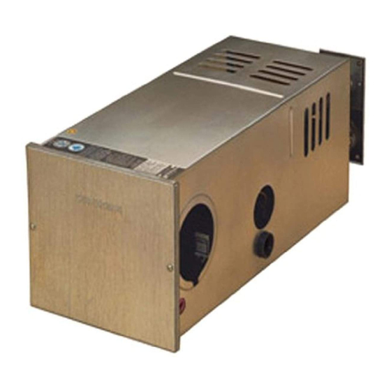
SUBURBAN MANUFACTURING COMPANY Post Office Box 399 Dayton, Tennessee 37321 SUBURBAN DYNATRAIL FURNACES Service Manual NT- 12S NT- 16S NT-20S NT-24SP NT-30SP NT-34SP NT-25K NT-30K NT-35K NT-42T...
Page 2
Gas Pressure Requirements/Service Tools Sequence of Normal Operation Operation Information Maintenance Cautions Furnace Removal Service Hints, Diagnosis and Corrective Measures for Suburban 12-volt DC Electronic Ignition Furnaces Service Center Information/Flat Rate Schedule Limited Warranty Optional Extended Warranty Service Test Service Answer Sheet SAFETY...
Page 3
Once the main burner flame is established, it is sustained by the air supplied by the blower. Suburban furnaces operate on 12-volt DC current that is supplied either by a 12-volt battery or a converter system. A recreational vehicle furnace that is specifically designed for "park model"...
Page 8
SEQUENCE OF NORMAL OPERATION The electronic ignition system is made up of three main parts: the module board, the electrode assembly, and the electrode wire. The module board is the brain of the electronic ignition system and it has several functions. 1.
Page 9
All DYNATRAIL direct ignition furnaces must have a flame sensing circuit through the control module that senses the presence of main burner flame. If proper flame sensing is not obtained or if the burner fails to light, the furnace must go into 100% lockout. When lockout occurs, the valve closes and will remain closed until the thermostat circuit is broken.
Page 10
A yearly inspection should be made of all gaskets on the furnace. If any gaskets show signs of leakage or deterioration, they must be replaced to assure proper pressurization of the sealed combustion chamber. Motors used on RV furnaces are permanently lubricated and do not require oiling. CAUTIONS Never operate the furnace with the electrode wire disconnected or with the electrode assembly removed from the furnace.
Page 11
SERVICE HINTS, DIAGNOSIS, AND CORRECTIVE MEASURES FOR THE IGNITION SYSTEMS OF SUBURBAN 12-VOLT DC ELECTRONIC IGNITION GAS FURNACES Furnaces with Direct Spark Ignition: Each step in this operation must be completed in the listed order before the next function will occur. To properly diagnose a malfunction and correct it, it must be determined at what step the operation of the furnace failed.
Page 12
A. Thermostat Is Calling For Heat, but The Blower Does Not Run: 1. Check for 12 volts DC at the furnace connection. Correct power source if "0" volts or below 12 volts DC. 2. Check all wiring for correct polarity (refer to wiring diagram), loose connections and possible shorts.
Page 13
6. Check the ducting of the furnace to determine proper airflow away from the furnace. See the installation manual for correct duct requirements. If the ducts have severe bends or kinks in the hose, the airflow may be restricted enough to cause the microswitch to bounce back from the volume of air hitting the cabinet front.
Page 14
D. Burner Ignites But Shuts Off: 1. Check to be certain that flame sensor is over slots in the main burner and that the main burner flame is burning against the tip of the flame sensor - adjust by bending the sensor probe.
Page 15
H. Unit Going Into Lockout Only Once In A While: 1. Thoroughly check the electrode and burner air adjustments. 2. Lockout can occur if the gas pressure fluctuates at the time that the thermostat calls for heat. Pressure fluctuations can be caused by a malfunctioning gas bottle regulator, and obstruction or a kink in the gas line, or moisture in the gas bottle regulator or in the gas lines.
Page 16
4. Check the high voltage - 14.5 volts DC maximum High voltage could intermittently produce volt surges or AC spikes that could damage the module board. Supply voltage to furnace should be checked if repeated module board failures occur. 5. Be sure duct connections to the furnace are airtight. Seal duct collar connections to the furnace cabinet with duct tape, if necessary, to prevent hot air leakage.
Page 18
If you would like more information on having your agency listed as a Suburban Recommended RV Service Center, please contact our Service Department at:...
Page 19
.25 ..1.25 Replace Limit Switch .25 ..All other jobs that are not listed, contact Suburban factory Service Department approval. NOTE: When more than one component is defective, compute the total of both replacement times but only one set-up time.
Page 20
Bill of Sale, a cancelled check or other payment record, Suburban will replace or repair, at its sole option, any parts that are found defective within the first year and will pay a warranty service allowance to the authorized Suburban Service Center at rates mutually agreed upon between Suburban and its authorized service centers.
Page 21
9. Suburban products whose serial number has been altered, defaced or removed. 10. Suburban products installed outside the Continental U.S.A., Alaska and Canada. 11. ANY SPECIAL, INDIRECT OR CONSEQUENTIAL PROPERTY, ECONOMIC OR COMMERCIAL DAMAGE OF ANY NATURE WHATSOEVER.
Need help?
Do you have a question about the NT-12S and is the answer not in the manual?
Questions and answers