Sign In
Upload
Download
Table of Contents
Contents
Add to my manuals
Delete from my manuals
Share
URL of this page:
HTML Link:
Bookmark this page
Add
Manual will be automatically added to "My Manuals"
Print this page
×
Bookmark added
×
Added to my manuals
Manuals
Brands
Optima Scale Manuals
Accessories
OP-901 SERIES
User manual
Optima Scale OP-901 SERIES User Manual
Hide thumbs
Also See for OP-901 SERIES
:
Installation manual
(2 pages)
1
Table Of Contents
2
3
4
5
6
7
8
9
10
11
12
13
14
15
16
17
18
19
page
of
19
Go
/
19
Contents
Table of Contents
Troubleshooting
Bookmarks
Table of Contents
Table of Contents
Safety Precautions
Preparations and Set up
Features
Specifications
Power Supply
Displays
Display and Key Descriptions
Operating Instructions
Calibration
Indicator Parameter Settings
Indicator Parameter Settings
Definitions
Connectors
Communication Mode
Troubleshooting
Contact Us
Advertisement
Quick Links
1
Preparations and Set up
2
Specifications
3
Calibration
4
Indicator Parameter Settings
5
Connectors
6
Troubleshooting
Download this manual
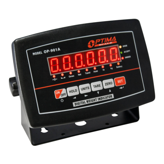
OP-901 SERIES INDICATOR
USER'S MANUAL
(OP-901A, OP-901B Series)
optimascale.com
Table of
Contents
Previous
Page
Next
Page
1
2
3
4
5
Advertisement
Table of Contents
Need help?
Do you have a question about the OP-901 SERIES and is the answer not in the manual?
Ask a question
Questions and answers
Related Manuals for Optima Scale OP-901 SERIES
Printer Optima Scale OP-412T Installation Manual
(2 pages)
Accessories Optima Scale OP-900 SERIES User Manual
Op-900 series (30 pages)
Accessories Optima Scale OP-901B Series User Manual
(19 pages)
Accessories Optima Scale OP-901A Series User Manual
(19 pages)
Accessories Optima Scale OP-903 User Manual
Portable static weighing indicator (21 pages)
Accessories Optima Scale OP-902 User Manual
(15 pages)
Accessories Optima Scale OP-904 User Manual
Panel mount indicator (22 pages)
Accessories Optima Scale OP-905 User Manual
(31 pages)
Accessories Optima Scale OP-918M User Manual
Pallet jack indicator (19 pages)
Accessories Optima Scale OP-918 User Manual
Pallet jack indicator (20 pages)
Accessories Optima Scale OP-900-LD User Manual
(18 pages)
This manual is also suitable for:
Op-901b series
Op-901a series
Table of Contents
Save PDF
Print
Rename the bookmark
Delete bookmark?
Delete from my manuals?
Login
Sign In
OR
Sign in with Facebook
Sign in with Google
Upload manual
Upload from disk
Upload from URL


Need help?
Do you have a question about the OP-901 SERIES and is the answer not in the manual?
Questions and answers