Optima Scale OP-900 SERIES User Manual
Op-900 series
Hide thumbs
Also See for OP-900 SERIES:
- Installation manual (2 pages) ,
- User manual (30 pages) ,
- User manual (30 pages)
Table of Contents
Advertisement
Advertisement
Table of Contents

Related Manuals for Optima Scale OP-900 SERIES


Summary of Contents for Optima Scale OP-900 SERIES
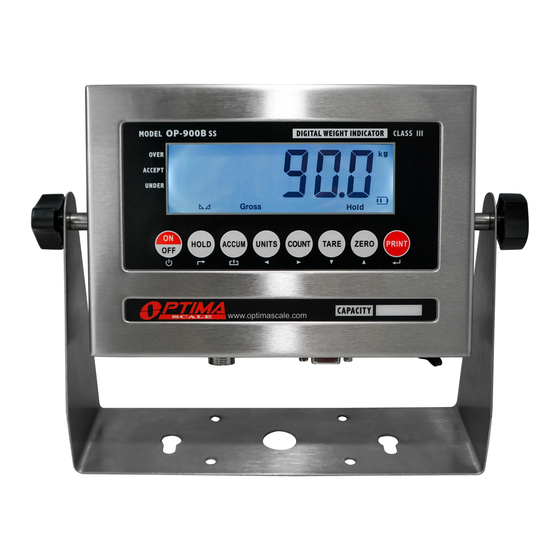
- Page 1 OP-900 SERIES INDICATOR USER’S MANUAL (OP-900A, OP-900B Series) optimascale.com...
-
Page 2: Table Of Contents
TABLE OF CONTENTS Safety Precautions Preparations and Set Up Features Specifications Power Supply Displays Display and Key Descriptions Operating Instructions Calibration Indicator Parameter Settings 12-16 Helpful Definitions Connectors 18-19 RS232 Serial Output Format 20-23 4-20 mA Analog Output Relay Output Troubleshooting Q&A Contact Us... -
Page 3: Safety Precautions
SAFETY PRECAUTIONS For safe operation of the weighing indicator, please follow these instructions: ● Calibration inspection and maintenance of the indicator are prohibited by non-pro- fessional staff ● Please ensure that the indicator rests on a stable surface ● The indicator is a piece of static sensitive equipment; Please cut off power during electrical connections ●... -
Page 4: Features
● Wireless capability (optional) ● Rechargeable battery (optional) Indicator Model Options The OP-900 series consists of the OP-900A (LED) series and OP-900B (LCD) series. Options for rechargeable battery, stainless steel enclosure, washdown enclosure, computer connection, relay output and analog output can be added. -
Page 5: Specifications
SPECIFICATIONS FIGURE 1: INDICATOR MEASUREMENTS... -
Page 6: Power Supply
POWER SUPPLY AC Adapter If the indicator is powered by an adapter, plug the adapter directly into the “DC” pin located at the bottom of the indicator. We recommend to plug into a wall outlet to avoid interference with other wirings. Battery (Optional) If you have an indicator with the rechargeable battery option, please charge the internal battery fully before first time use. -
Page 7: Displays
OP-900A (LED) OP 900B (LCD) -
Page 8: Display And Key Descriptions
DISPLAY AND KEY DESCRIPTION ON/OFF Powers the Indicator On or Off if held for 2 seconds HOLD Holds the weight (5 Hold options; can be changed in parameter settings) TOTAL 1. Accumulates weights 2. Works with “Print” to perform the accumulation function and check the accumulation result UNITS Shifts between weighing units... -
Page 9: Operating Instructions
OPERATING INSTRUCTIONS Power On ● Turn on the power by pressing the power button for 2 seconds. Once on, the scale will flash the voltage and then begin to auto-check and count down from 0-9 sequentially before entering the weighing mode Note: Anything on the scale before powering on will automatically be tared out. - Page 10 Counting Function ● The counting function is used to count a high volume of identical parts. You can do this by setting a sample and then either adding to the sample or taking away from the sample to count the number of objects on the scale ●...
- Page 11 Hold There are 4 different hold functions you can choose from in the C11 parameter 1. Peak Hold: Grabs the highest weight (for materials testing, ie. tension and pulling force) ● Press the HOLD key then add weight to the scale ●...
-
Page 12: Calibration
CALIBRATION PROCEDURE Turn on the scale by holding ON/OFF for 2 seconds. Press HOLD and PRINT together to access the setup menu. If done correctly, the display should now show Press PRINT to access the C1 channel. The display should show [ Press ZERO to choose which unit you want to calibrate in (1 = kg, 2 = lb). - Page 13 23. Enter the calibration weight value you will use (at least 10% of max capacity you set in C04 by using UNIT and COUNT to move the cursor left and right, and TARE and ZERO move the values down and up. 24.
-
Page 14: Indicator Parameter Settings
INDICATOR PARAMETER SETTINGS The parameter settings menu has a calibration section (C01 to C07 explained above) and a parameter settings section (C08 and up). To access the calibration section the seal switch (located at one corner of the PCB) must be OFF. - Page 15 Function Parameter Settings/Options Restore Default 0 = do not restore Settings 1 = restore to default settings Warning Tone 0 = turn off warning tone 1 = turn on warning tone Automatic 0 = turn off auto power off Power Off 10 = power off automatically if no change within 10 minutes 30 = power off automatically if no change within 30 minutes 60 = power off automatically if no change within 60 minutes...
- Page 16 Function Parameter Settings/Options Manual 0 = turn off manually zero setting Zero Range 1 = ±1% max capacity 2 = ±2% max capacity 4 = ±4% max capacity 10 = ±10% max capacity 20 = ±20% max capacity 100 = ±100% max capacity Initial Zero Range 0 = no initial zero setting 1 = ±1% max capacity...
- Page 17 Function Parameter Settings/Options Noise Filter 0 = turn off noise filter 1 = 1 digital filter strength 2 = 2 digital filter strength 3 = 3 digital filter strength Print Time and Date 0 = yy.mm.dd 1 = mm.dd.yy 2 = dd.mm.yy 3 = yy.mm.dd Analog Output Setting 0 = 0 - 5V ouput...
- Page 18 Table 3. Default Parameter Settings Function Parameter Default Setting Weighing Unit Decimal Setting Graduation Setting Maximum Capacity 1000 Zero Calibration Calibration Restore Default Warning Tone Automatic Power Off Power Saving Mode Hold Function Unit Conversion Upper Limit Alarm 000000 Lower Limit Alarm 000000 Inner Code Display Set Date...
-
Page 19: Helpful Definitions
HELPFUL DEFINITIONS Division: The amount of increments a scale offers. How accurate the scale can be Capacity: the maximum amount the scale can contain Initial Zero Range: The percentage of weight allowed on the scale when indicator is powered on that will automatically zero. example: If initial zero range is set to 10% of the max. -
Page 20: Connectors
CONNECTORS Connecting load cells to the indicator ● The indicator can connect with 6 load cells of 350Ω at most ● 4 wire or 6 wire load cell connections are both okay ● Please contact us directly if you have other special needs for your application ●... - Page 21 FIGURE 3: INNER TERMINAL BLOCK CONNECTION DIAGRAM Table 4. Wiring Color Code Signal Name Color Code Description +Exe/ +EX Positive excitation voltage to load cell +IN / +SIG GREEN Positive output signal from load cell HD / SHLD YELLOW/THICK BLACK Shield Wire -IN / -SIG WHITE...
-
Page 22: Rs232 Serial Output Format
RS232 SERIAL OUTPUT FORMAT Follow the pin out of Table 5 below to connect the indicator the RS-232 Serial device Table 5. DB9 Pin Description DB9 Pin Definition Function Transmit Data Receive Data Ground Interface The serial output format depends on the settings for parameter C18. The serial output consists of a string of ASCII characters. - Page 23 Remote Display Continuous Sending Mode (C18=1) For use with a Scoreboard/Remote Display Note: Baud Rate must be set to 1200 (C19 = 0) Output Continuous Format State A Bits0,1,2 Decimal point position XXXXXX0 XXXXXXX XXXXX.X XXXX.XX XXX.XXX Bits3,4 Division State B BitsS function Bits0...
- Page 24 Print Mode (C18 = 2) For printing on a non-adhesive ticket printer. Parameters 16, 17, 30, & 42-45 all effect your ticket print out. Normal weighing ticket printout example: Date: 05/01/2017 Time: 11:30:52 Net: 25.6lb Tare: 10.3lb Gross: 35.9lb Accumulation weighing ticket printout example: Date: 05/01/2017 Time:...
- Page 25 Computer Continuous Sending Mode (C18=4) CR LF Data weight status, ST=standstill, US=not standstill, OL=overload weight mode, GS=gross mode, NT=net mode weight of positive and negative, “+” or “-” Data: weight value, including decimal point “kg” or “lb” carriage return line feed PC or Remote Display Continuous Sending Mode (C18=5) <STX>...
-
Page 26: Ma Analog Output
4-20 mA ANALOG OUTPUT (OPTIONAL) FIGURE 6. CONNECTION DIAGRAM The 4-20 mA analog output of the OP-900 scale is a voltage sourcing sensor that will output current which is proportional to the calibrated scale’s weight range (i.e. 4 mA = 0 LBS and 20 mA = 10,000 LBS). -
Page 27: Relay Output
RELAY OUTPUT (OPTIONAL) ● The indicator can output 4 signals, which when connected to outside equipment, can perform an automatic control function and an upper/lower limit alarm function. ● Change parameter setting C33 following Table 6 below: Table 6: Relay Output Parameter Setting Output Port Port Definition Function Out1... -
Page 28: Troubleshooting
TROUBLESHOOTING Error Codes Error Reason Solution 1. Overload 1. Reduce the weight 2. Wrong connection with load cell 2. Check load cell connection UUUUUU 3. Load cell has quality problem 3. Inspect load cell; Check the input/output 4. See Q&A section 1. -
Page 29: Q&A
Q&A The scale does not turn on Make sure the power cord is plugged in, and that there is power. One easy way to test this is by connecting another appliance to the same outlet and see if it’s operational The reading goes negative when a load is applied Try interchanging the Sig+ and Sig- wiring connected to the load cell and/or junction box (if one is used) -
Page 30: Contact Us
CONTACT US Please e-mail sales@optimascale.com for any sales related questions. Please e-mail support@optimascale.com for any support related questions. Don’t forget to visit our website at: optimascale.com...
Need help?
Do you have a question about the OP-900 SERIES and is the answer not in the manual?
Questions and answers