Table of Contents
Advertisement
Advertisement
Table of Contents

Related Manuals for Cloud BT-IFW


Summary of Contents for Cloud BT-IFW
- Page 1 BT -1 Series Bluetooth Wireless Audio Module STATUS BT-1FW (UK, White) BT-1FB (UK, Black) BT-1EW (UK, White) TO PAIR PUSH BT-1EB (UK, Black) BT-1 STATUS BT-1AFW (USA, White) BT-1AEW (USA, White) PUSH TO PAIR BT-1 Installation Guide BT-1 Installation Guide v1.0...
-
Page 2: Conformities
Conformities The BT-1 is compliant with the following EMC directives: EN 301 489-17 V2.1.1 EN 300 328 V1.8.1 EN60950-1:2006+A11:2009+A1:2010+A12:2011 BT-1 Installation Guide v1.0... -
Page 3: Table Of Contents
Contents Conformities ........................... 2 Introduction ............................ 4 BT-1 variants ................................... 4 Mounting - mechanical ........................4 Faceplate Controls ......................... 5 Block Diagrams ..........................6 Installation - connections ......................7 Connection to a Facility Port (BT-1F only) ......................7 Connecting to an Extension Port (BT-1E only) ....................... 9 Connecting a BT-1F to an LM-2.......................... -
Page 4: Introduction
Introduction The BT-1 is a wireless remote audio input module for use with all Cloud products fitted with an RJ45 Facility Port or an RJ45 Extension Port. The BT-1 enables compatible portable devices such as laptops, tablets and smartphones to stream audio wirelessly to the interface, and thus into the audio system of the Zone where the interface is installed. -
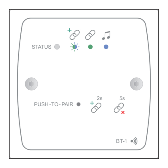
Page 5: Faceplate Controls
Faceplate Controls STATUS PUSH TO PAIR BT-1 UK version illustrated PUSH-TO-PAIR – recessed push-button accessed through a 2 mm dia. hole. The two “chain” symbols adjacent to the access hole depict the effect of “short” and “long” presses on the button: Short press: Pressing the button for 2 secs puts the BT-1 into “Awaiting Pairing”... -
Page 6: Block Diagrams
Block Diagrams BT-1F BT-1E BT-1 Installation Guide v1.0... -
Page 7: Installation - Connections
Installation - connections Connection to a Facility Port (BT-1F only) The BT-1 has two PCBs “piggy-backed” onto the rear of the faceplate. The RJ45 output connector (SK1) is located on the upper PCB: RJ45 OUTPUT CONNECTOR INSERT PLUG THIS WAY, LATCH UPWARDS LOCATION OF REAR RJ45 CONNECTOR (Sketch simplified;... - Page 8 IMPORTANT: Because the cables carry low-level audio, only screened Cat 5 should be used, the foil screen of the cable being bonded to the metal screening can of the plugs. If a BT-1 is being installed in very close proximity to the host unit, it may be possible to use ready-made screened Cat 5 “patch”...
-
Page 9: Connecting To An Extension Port (Bt-1E Only)
Connecting to an Extension Port (BT-1E only) The BT-1E is connected in exactly the same manner as the BT-1F, except that it should be connected to an EXTENSION PORT on the host unit. Connect to SK1 100 m max HOST UNIT (DCM1 illustrated) Screened Cat 5 cable BT-1... -
Page 10: Connecting A Bt-1F To An Lm-2
Connecting a BT-1F to an LM-2 If a BT-1F is being installed in a Zone which also contains an LM-2 Remote Input/Control Module, it should be connected to the LM-2’s LINK connector instead of directly to the host unit, as shown below: 100 m max BT-1F Connect to... -
Page 11: Connecting An Rl/Rsl Plate To A Bt-1F
Connecting an RL/RSL plate to a BT-1F The BT-1F is provided with a 3-pin screw-terminal connector (on the rear PCB) to permit the connection of an RL-1 or RSL-6 remote control plate. These plates normally connect to the Music Control Port for the relevant Zone at the host unit, but it may simplify wiring to connect one to the BT-1. -
Page 12: Set-Up Options
Set-up Options Setting up the BT-1 is very simple: there are two 4-way DIP switches on the lower rear PCB which may need to be set to configure the BT-1 to suit the specifics of the installation. SECURE/ RF POWER BLUETOOTH NON-SECURE LEVEL... -
Page 13: Rf Power Setting
RF power setting The RF power level at which the Bluetooth interface operates – and hence the operational range of the BT-1 – is adjustable. Units are shipped with the power setting at maximum, but in some installation circumstances, it may be desirable to limit the power of the module, thereby restricting the operational range. -
Page 14: Bluetooth Ident
Bluetooth ident In installations where multiple BT-1s are installed, it will generally be desirable to give each a unique identifier. The right-hand DIP switch (viewed from the rear) allows one of 16 idents to be assigned to each BT-1. The BT-1 appears in the Device List on a user’s laptop, tablet, etc., with a numeric suffix (#01 to #16) to indicate all the BT-1s that are within range;... -
Page 15: Power Considerations
Zones. If there is any doubt about the power capability, please refer to the host unit’s Installation and User Guide where full details of power supply ratings can be found. Should you have any questions concerning the installation and connection of the Cloud BT-1, please visit www.cloud.co.uk/resources, where you will find additional technical information. - Page 16 www.cloudusa.pro...
Need help?
Do you have a question about the BT-IFW and is the answer not in the manual?
Questions and answers