Table of Contents
Advertisement
Quick Links
Advertisement
Table of Contents

Summary of Contents for DANHAG APP-control
- Page 1 APP - Control Version v10.x as of 02.2018 Operating manual...
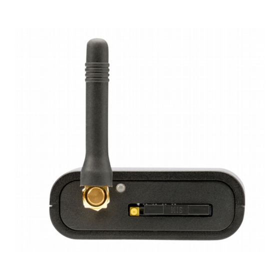
- Page 2 Antenna Status LED Release SIM card connection Front view GPS LED Release Release (connector I) (connector II) PIN1 PIN8 Rear view...
-
Page 3: Table Of Contents
Table of content 1 Scope of delivery..................... 5 2 Safety instructions................... 6 3 Intended use....................6 4 Obligation and liability..................7 5 Malfunction..................... 8 6 Disposal......................8 7 Declaration of conformity................8 7.1 Typengenehmigung................8 8 Device description................... 9 8.1 Difference BASIC / W-BUS / E-BUS............9 8.2 Alarm function................... -
Page 5: Scope Of Delivery
APP-control v10.x Scope of delivery APP-control • GSM-antenna (straight) • connection line (14-pole connector) • operating manual • optional available accessories vehicle-specific cable harnesses • indoor window antenna • Antenna adapter (FME to SMA) • GPS-receiver • external temperature sensor •... -
Page 6: Safety Instructions
/ or damage may occur. Intended use The APP-control allows the switching of any device per APP, SMS or call. The APP-control is designated for private use and not for commercial purposes. The APP-control has to be used exclusively according to the instructions of thes operating manual. -
Page 7: Obligation And Liability
The APP-control has been developed and manufactured according to the current technical status and the recognized safety rules. It cannot be assured, however, that the APP-control will operate as intended under all circumstances, at any time and under all conditions. -
Page 8: Malfunction
APP-control v10.x Malfunction The APP-control must taken out of service immediately when it might be assumed that a safe operation cannot be guaranteed any more. All appropriate measures must be taken to exclude an unintentional re-commissioning. Only a qualified person os allowed to perform a repair. -
Page 9: Device Description
E-BUS 5 W-BUS 6 E-BUS 6 E-BUS 7 E-BUS 8 The APP-control "W-BUS" and "E-BUS" are supporting different output signals. An overview about the signal needed for your vehicle or heater can be found at our website: www.danhag.de 9 - 32... - Page 10 You can query the current status of the heater by sending a sms with the text "INFO" to the APP-control. BASIC, W-BUS The status displays the state of the APP-control. E-BUS The E-BUS version communicates with the heater and can display the current state of the heater.
-
Page 11: Alarm Function
If the operating-time can't be queried, the default value will be used. Alarm function The APP-control is equipped with an alarm input which can be connected to an existing alarm system. After connecting the power supply to the APP-control, the voltage level on the alarm input will be stored (0 or +12V). -
Page 12: Switching Acknowledgment
8.3.1 Switching by call When switching the APP-control by call, you will hear a dial tone. During this time the caller's ID will be analyzed. In case of a valid phone number th switching operation will be released and you will hear a busy tone. -
Page 13: Sim-Card
APP-control v10.x SIM-card Any SIM card is required for the operation of the APP-control (Prepaid or subscription). Inserting the SIM card Disconnect the power supply from the device • remove the SIM card holder • (Pleas press the „release button“ slightly to release the holder) insert the SIM card into the holder •... -
Page 14: Inputs And Outputs (Connector I)
APP-control v10.x Inputs and Outputs (connector I) PIN color description function yellow Switching output 1 W-BUS, E-BUS black Switching output 2 Output +12V, max. 1A purple Switching output 3 ground, max. 500mA output GND output GND 1KOhm for ext. LED... - Page 15 APP-control v10.x PIN color description function Relais Relais Relais blue input alarm Input for an existing alarm system +12V / GND (see alarm function) orange input ignnition The inputs and outputs marked with "•" must be connected for the basic functionality of the device. All further connections can be used optionally.
-
Page 16: Electrical Connection
11.1.2 heater with radio remote control The APP-control is connected to the already existing receiver of the remote control, using the y-cable which is included into delivery. The Y-cable also ensures the power supply of the APP-control. -
Page 17: Connection Of Ext. Button
DANHAG button 14pol. connector of APP-control 11.2.1 Difference between button and switch Button: Pressing the button shortly (approx. 1s) will switch on the heater for the preset time. If you want to switch of the heater you have to press the button once again. -
Page 18: Accessories Connection
GPS-receiver 12.2 The APP-control supports an external GPS-receiver which can be connected to the aux-socket at the back of the module. If the ignition is switched on the position is determined about every 1 second and can be queried via SMS. If the ignition is switched off, the GPS-receiver is activated during determining the position only. - Page 19 If you want to update the position when the ignition is turned off, you will have to send a SMS with the text „XGPS“ to the APP-control. The GPS-receiver is turned on for about 3 minutes and determines the current position.
-
Page 20: Start Up
APP-control • After connecting the power supply , the APP-control will perform a selftest. The LED will be lighting red for approx. 4 seconds and then begins to flash red (network search). As soon as the APP-control is logged in into the GSM network, the LED will be flashing green. -
Page 21: Configuration
APP-control v10.x Configuration After the first start you have to configure the APP-control per SMS once. The settings are stored, even in case of disconnecting the power supply. The following functions and settings can be configured: Password for the SMS configuration you will need the 5-digit password •... - Page 22 APP-control v10.x Switch-on delay (BASIC, W-BUS) Determines if switching output 2 is switched simultaneously with output 1. You can configure a switch-on delay, so output 2 will be switched after output 1. Switch-off delay (BASIC, W-BUS) Determines if switching output 2 and 3 are switched off simultaneously with output 1.
- Page 23 Phone number 1 is the master number to which all info SMS will • always be sent The APP-control will perform the switching operation only if it is • switched by one of the authorized phone numbers per APP, SMS or call Please enter the phone number with the international prefix (e.g.
-
Page 24: Table Parameter
APP-control E-BUS v10.x Table parameter 14.1 Nr. function setting remark Password 5 digits preset "12345" Master number max. 17 digits Enter phone numbers with international prefix. Phone number 2 Germany +49 ... Phone number 3 Austria +43 ... Phone number 4 e.g. -
Page 25: Configuration With Sms Configurator
Running time: 25 minutes • Syntax: 12345;11=+49305627853;12=+491706878981;20=25;# Delete a phone number 14.4 You can delete a phone number by overwriting it with "0". Reset 14.5 To reset the APP-control, please disconnect the power supply for about 5 sec. 25 - 32... -
Page 26: Sms-Commands
APP-control v10.x SMS-commands 14.6 You can control the GSM remote control by APP, SMS or call. The following table shows the supported SMS commands. command function INFO Query of current settings TEMP Query the temperature switches the heater on ON:20... - Page 27 APP-control v10.x 14.6.1 INFO SMS You can query the current settings of the APP-control by sending an SMS with the Text "INFO" to the APP-control. Then you will receive an SMS with a summary of the settings to the master number.
-
Page 28: Trouble Shooting
No switching Not / incorrectly • Phone number existing twice operation at all configured on SIM card • APP-control not configured yet delete all phone numbers / SMS on SIM cardand re-configure No INFO-SMS query Kno credit on SIM Load credit... -
Page 29: Manufacturer
APP-control v10.x Manufacturer Ing. Büro Gornicki Boizenburger Str. 30 D - 12619 Berlin E-Mail: info@danhag.de Webseite: www.danhag.de technical data Supply voltage: 10 - 15 VDC Current consumption: Standby ca. 10mA, shortly max. 2A Switching output 1: E-BUS Switching output 2: +12V, max 1A Operating temperature: -30°C bis 80°C... -
Page 30: Installation Location
APP-control v10.x Installation location Mark the installation location of the APP-control. 30 - 32... - Page 32 Please visit www.danhag.de for an german version of this users guide. *740409* 740409...
Need help?
Do you have a question about the APP-control and is the answer not in the manual?
Questions and answers