Advertisement
Quick Links
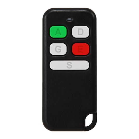
Intruder alarm system
The LT5 remote control is portable wireless transmitter for use only with Pxx series wireless alarm systems (P16, P32 or P64) or with PAS8xx series control panel that has wireless
extension module EXT116S connected to the system bus.
Dimensions (W x H x D)
33 mm x 73 mm x 11 mm
LT5 b
uttons
and
are typically used for arming and disarming, then
change the default
remote control unit (RCU)
1
Downloading the template from the system to software MASCAD
1. Connect USB cable to keypad USB terminal.
2. Establish the connection with a computer:
KM20Bx:
, Service Mode
0000 (default),
Project Loading
KM24x:
, Service Mode
PIN: 0000 (default),
Project Loading
3. Run the the software MASCAD.
4. Click on tab Project Data Sending / Receiving.
5. Click on the button Get data from the keypad and wait until all data will be downloaded.
6. Give a reasonable name to the project (pop up window will appear automaticaly).
7. Click on button Save.
2
Modifying the template for remote control unit LT5
1. Click on tab Modules.
2. Click on row Set template for RCU (LT5, HC3S).
3. Click on button Set template for LT5.
4. Modify template according user needs:
Button
- used for arming mode selection. The most preferred arming mode should
be on the top of the list, and the other modes should be aligned in order of priority. The
LED color that corresponds the arming mode cannot be changed.
Button
- this button is used exclusively to disarm, it's function cannot be changed. If
the system is signalling because of an alarm, the user will turn off the alarm along with
disarming.
Buttons
,
- these buttons are of equal functionality. Each of the buttons can be
assigned up to four control commands if the
command. If the
button for sending the command wont be used, only one control
command can be assigned to it. The most preferred command should be on the top of
the list, and the other commands should be alignet in order of priority. The LED color
assigned to the control command cannot be changed.
Commands:
Fire alarm - used to trigger a fire alarm.
Medical alarm - used to trigger a medical alarm.
Panic alarm - used to trigger a panic alarm.
Clear alarms - used to stop the signaling because of an alarm.
Pre-alarm group ... on - used to turn on the special arming mode Pre-alarm.
Pre-alarm group ... off - used to turn off the special arming mode Pre-alarm.
PGM ouput control ... - used to control the system PGM outputs. PGM output definition
must be Mono/Bi Switch (see tab PGM outputs).
Macro 1...8 - used to control the system with several commands in programmed order
of sequence. The amount of commands in one macro-command depends on the
amount of used macro-commands and the amount of commands in them.
5. Assign the arming modes / commands to each of remote control unit buttons.
6. Click on Edit button if the command requires more settings to set.
7. Click on button Save when arming modes / all commands are assigned to buttons.
3
Uploading the modified template to the system
1. Click on tab Project Data Sending / Receiving.
2. Click on the button Send data to the keypad and wait until all data will be uploaded.
3. Take a look on keypad LCD screen. Wait until the message Processing ... disapears.
4. Leave the service mode (several times press keys
4
Assigning the remote control unit to the user
1. Go to menu:
KM20Bx:
, Settings
KM24x: , Settings
,
Users
ENT
ENT
ENT
ENT
2. Simultaneosly hold down the buttons
3. Message Done should appear on keypad LCD when remote control unit is enrolled succesfully.
4. Release buttons
and
.
5. Please wait at least 40 seconds before starting to test all functions for proper operations.
Ambient temperature
Ambient humidity
o
o
0% - 70%
-10 C - +55 C
template it
can be done with a software MASCAD.
, enter User PIN: 0001 (default), enter Service PIN:
ENT
,Open USB Port
.
ENT
ENT
, enter user PIN: 0001 (default), enter service
ENT
ENT
ENT
ENT
, Start connection with PC
ENT
ENT
ENT
ENT
button will be used to send the
or ).
CLR
CLR
CLR
CLR
CLR
,
Users
,
Edit Users
ENT
ENT
,
Edit Users
, enter User PIN: 0001 (default),
ENT
ENT
ENT
ENT
ENT
and
.
SPECIFICATIONS
Operating frequency
Depends on firmware version of the transmitter:
1 = 868,30 MHz (EU)
9 = 915,30 MHz (AU)
TEMPLATE
or
buttons can be programmed for any task (ex. to control
.
ENT
ENT
ENT
ENT
, enter User PIN: 0001 (default),
ENT
Controls
Remote control LT5
Battery
CR2032, 3V
gate
s, to trigger a panic alarm). In order to
Controls
,
...
New RCU
, Waiting ...
ENT
ENT
... , New RCU
, Waiting ...
ENT
ENT
ENT
ENT
Installation manual
Battery lifetime
LT5 > 3 years
Page 1
Advertisement

Subscribe to Our Youtube Channel
Related Manuals for SECOLink LT5


Summary of Contents for SECOLink LT5
- Page 1 Installation manual The LT5 remote control is portable wireless transmitter for use only with Pxx series wireless alarm systems (P16, P32 or P64) or with PAS8xx series control panel that has wireless extension module EXT116S connected to the system bus.
- Page 2 Remote control LT5 Remote control LT5 Intruder alarm system Intruder alarm system Installation manual Installation manual EXAMPLES OF USE EXAMPLES OF USE Arming Arming Note: this example shows how to arm the system in Away arming mode. This arming mode is represented by Red color light on LED at the arming mode selection while pressing Note: this example shows how to arm the system in Away arming mode.
Need help?
Do you have a question about the LT5 and is the answer not in the manual?
Questions and answers