Delsys TRIGNO User Manual
Emg system
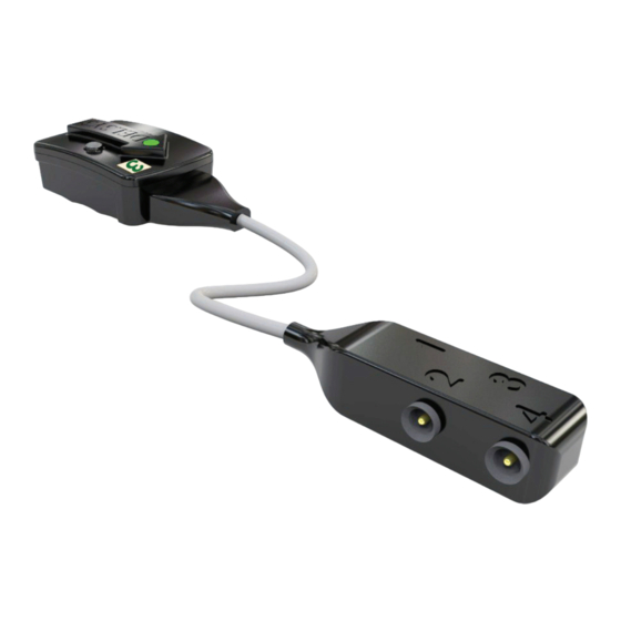
4-channel fsr adapter
Hide thumbs
Also See for TRIGNO:
- User manual (32 pages) ,
- User manual (18 pages) ,
- User manual (22 pages)
Table of Contents
Advertisement
Quick Links
Download this manual
See also:
User Manual
Advertisement
Table of Contents

Subscribe to Our Youtube Channel
Related Manuals for Delsys TRIGNO


Summary of Contents for Delsys TRIGNO
- Page 1 TRIGNO EMG System 4-Channel FSR Adapter User’s Guide Copyright © Delsys Incorporated Delsys Logo and EMGworks are Registered Trademarks of Delsys Inc. MAN-019-1-3...
-
Page 3: Table Of Contents
Table of Contents Important Information Intended Use Technical Service and Support Warnings and Precautions Device Information Disclaimer System Requirements FSR Sensor Overview Using the Sensors Charging the Sensors Sensor Pairing Smart Sensors Working with the FSR Membranes Handling FSR Membranes Connecting the FSR Membranes to the Sensor Applying the FSR Membrane Placing the FSR Sensor... -
Page 4: Important Information
Important Information Intended Use The Trigno Wireless EMG Systems are battery-powered biofeed- back devices that enable researchers and clinicians to acquire EMG and related signals from subjects for biofeedback purposes. They are intended for relaxation training and muscle reeducation. Interpreta- tion of the EMG and supporting signals by a qualified individual is required. -
Page 5: Warnings And Precautions
Connect only to Delsys-approved devices. Connecting a patient to high-frequency surgical equipment while using Delsys EMG systems may result in burns at the site of the EMG sensor contacts. Immediately discontinue device use if skin irritation or discomfort occurs. -
Page 6: Device Information
Extended periods in the discharged state may damage the internal lithium polymer cell. Trigno Systems should be stored and operated between 5 and 40 degrees Celsius due to the presence of an internal Lithium Polymer rechargeable cell. - Page 7 Pursuant to Part 15.21 of the FCC Rules, any changes or modifica- tions to this product not expressly approved by Delsys Inc. might cause harmful interference and void the FCC authorization to op- erate this product.
-
Page 8: Disclaimer
DELSYS INC. makes no di- agnosis or prescription by virtue of anything about this product. System Requirements The Trigno 4-channel FSR Sensor is designed to be used with the Trigno Wireless EMG System. 4-Channel FSR Adapter User’s Guide... -
Page 9: Fsr Sensor Overview
One 4-channel FSR Sensor occupies one position of the 16 possible sensors in a Trigno network. Data are expressed as a percentage of the sensor’s full scale limits. These devices are useful for identifying the... -
Page 10: Using The Sensors
Trigno Base/Recharge Station. Energize the power supply by connecting it to a Mains outlet. Be sure to use the appropri- ate plug adapter for your location. Ensure that the Trigno sensors are properly fitted in the recharge pockets. The sensor LEDs will illumi- nate to amber during charging and green when charge is complete. -
Page 11: Sensor Pairing
Sensor Pairing Trigno sensors communicate with a custom wireless protocol that links each sensor to the active Trigno network This linking process is known as sensor “pairing”, and is initiated through the “Pair” com- mand in EMGworks. 1. Initiate sensor pairing in software. -
Page 12: Smart Sensors
Smart Sensors After pairing, the association of sensors to the Trigno System is re- tained for all future uses. Any configuration in EMGworks can be made to reflect the last paired set of sensors by clicking the “Refresh Smart Sensors”... -
Page 13: Working With The Fsr Membranes
Connecting the FSR Membranes to the Sensor The Trigno FSR Sensor has a connector head hosting 4 receptacles for the membrane transducers. Connect the FSR membranes by to the 4 barrel receptacles taking care to fully mate the plug. The connectors are labeled numbers 1-4 on the sensor, and portrayed in this order in the EMGworks software. -
Page 14: Applying The Fsr Membrane
Figure 9. Mating the FSR membrane connectors to the sensor connector head. Ensure that the barrels are fully inserted. Applying the FSR Membrane The FSR membranes can be used in a wide variety of circumstances and applications; thus each case must be evaluated for any particular challenges it may pose. - Page 15 Figure 13. FSR membrane options for varieties of applica- tions servicing 5 mm , 15 mm and 40 mm areas. Trigno EMG System...
-
Page 16: Placing The Fsr Sensor
1 footstrike, showing the time-course and relative intensity of each pressure point. Placing the FSR Sensor The Trigno FSR Sensor and the associ- ated connection head can be easily af- fixed to the surface of the body using the Delsys Adhesive interfaces. -
Page 17: Connecting The Fsr Sensor Analog Outputs
Connecting the FSR Sensor Analog Outputs When paired to a Trigno EMG System, the 4-channel FSR Sensor effectively replaces the EMG channel and 3 accelerometer channels (X, Y and Z) of the standard EMG sensor originally associated with those positions. As such, analog outputs of these channels will output the FSR analog signals. -
Page 18: Specifications
The analog output signal is scaled to full range of the FSR sensor, where an output of 0% in EMGworks corresponds to the most negative output of -4.85V and a full scale output of 100% corresponds to +5.00V. Refer to the Trigno EMG System User’s Guide for ad- ditional details on the analog output specifications.
Need help?
Do you have a question about the TRIGNO and is the answer not in the manual?
Questions and answers