Table of Contents
Advertisement
Quick Links
I
NSTRUCTION
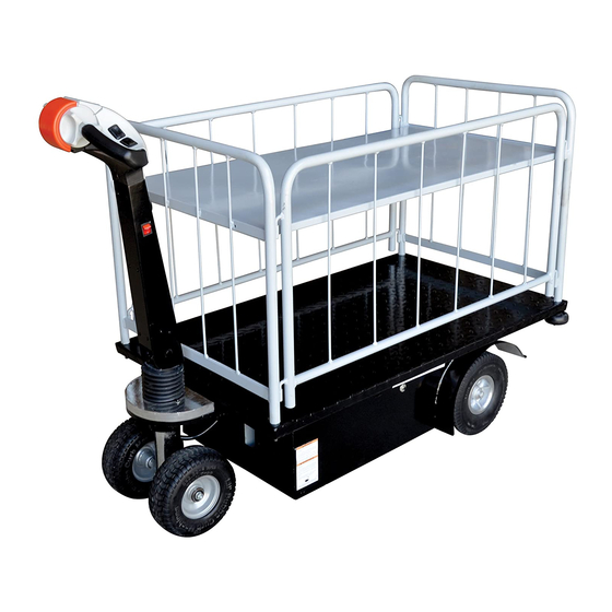
Two Speed Traction-Drive Carts
FOR
M
C
ODELS
OVERED
NE-CART-1
NE-CART-3
V
M
ESTIL
2999 N
W
ORTH
AYNE
T
: (260) 665-7586 -
ELEPHONE
U
:
.
RL
WWW
VESTILMFG
:
NE-CART-1, NE-CART-2, NE-CART-3, NE-CART-4
ANUFACTURING
S
, P.O. B
TREET
OX
- T
OR
OLL
F
: (260) 665-1339
AX
.
E
COM
MAIL
1
M
ANUAL
NE-CART-2
NE-CART-4
C
.
ORP
507, A
, IN 46703
NGOLA
F
(800) 348-0868
REE
:
@
SALES
VESTIL
.
COM
Advertisement
Table of Contents

Related Manuals for Vestil NE-CART-4

Summary of Contents for Vestil NE-CART-4
- Page 1 NSTRUCTION ANUAL Two Speed Traction-Drive Carts ODELS OVERED NE-CART-1, NE-CART-2, NE-CART-3, NE-CART-4 NE-CART-1 NE-CART-2 NE-CART-3 NE-CART-4 ESTIL ANUFACTURING 2999 N , P.O. B 507, A , IN 46703 ORTH AYNE TREET NGOLA : (260) 665-7586 - (800) 348-0868 ELEPHONE : (260) 665-1339...
-
Page 2: Table Of Contents
E-CART (ELECTRIC CART) ………………………………………………………………………………….. General …………………………………………………………………………… Specification ……………………………………………………………… Receiving instructions ……….…………………………………………………………… Rules for Safe use Safety Instructions & Warnings …………………………………………… Symbols & Pictures …………………………………………………………. ………………………………………………………………… Product description Designated use …. … …... … ……………………………………………………. ………………………………………………………………………………. Operation Travel ……………………………………………………………………………….. Safety Reverse Switch ……………………………………………………………. Brake …………... -
Page 3: General
E-CART (ELECTRIC CART) Introduction Read and follow the instructions contained in this operating manual. Please read and follow all instructions in this User’s Instruction Manual before attempting to operate your Material Handling Cart (E-CART) for the first time. If there is anything in this manual that you don’t understand, or if you require additional assistance for setting it up. -
Page 4: Specification
Specifications Model # NE-CART-1 NE-CART -2 NE-CART -3 NE-CART-4 Total Capacity 750 lbs 750 lbs 750 lbs 400 lbs 2nd Shelf Capacity 250 lbs 200 lbs Shelf Capacity 150 lbs Platform Size (L x W) 28 x 48” 24¾” x 46”... -
Page 5: Receiving Instructions
E-CART (ELECTRIC CART) Receiving Instructions Every unit is thoroughly tested and inspected prior to shipment. However, it is possible that the unit may incur damage during transit. If you see damage when unloading, make a note of it on the SHIPPER RECEIVER. Remove all packing &... -
Page 6: Rules For Safe Use
E-CART (ELECTRIC CART) Rules For Safe Use These symbols below are used in this owners manual to identify warnings and cautions. It is very important for to read and understand them. Warning: Failure to note the warnings in this users manual may result in personal injury Caution: Failure to observe the cautions in this users manual may result in damage to your E-CART. -
Page 7: Safety Instructions & Warnings
E-CART is designed for a maximum user weight limit of 750 lbs. (340 kgs.) Warning: Exceeding the weight limit will avoid your warranty and may result in personal injury and damage to E-CART. Vestil will not be held responsible for injuries and/or property damage resulting from failure to observe these weight limitations. -
Page 8: Symbols & Pictures
E-CART (ELECTRIC CART) up again slowly and then accelerate smoothly with caution. Avoid sudden stops, lean forward towards your handlebars to increase stability. Warning: Any attempt to climb or descend an incline steeper than shown below may put your E-CART in an unstable position and cause it to tip, resulting in personal injury. Max 5°... -
Page 9: Product Description
E-CART (ELECTRIC CART) Product description Designated use The CART is to be used on hard level surfaces. To move the stacker between buildings, warehouses etc The gradient of the slope must not be more than 5% Make sure load is not loose or unstable. Do not pick up loads on tips or forks or edge of platform. -
Page 10: Travel
E-CART (ELECTRIC CART) Travel The butterfly switch controls the direction and speed of the lift truck. Rotating the butterfly control towards the forks moves the truck in the forward direction. Rotating the butterfly control away from the forks, moves the truck in the reverse direction. -
Page 11: Horn
E-CART (ELECTRIC CART) TO BRAKE This cart is equipped with a brake that is applied between 1~5 degrees of the vertical position . When you release your hand from the handle. It will resume the neutral position automatically, as the brake in work. Always make sure that the brake is in work before operating the cart . -
Page 12: Maintenance And Repair
E-CART (ELECTRIC CART) Maintenance and repair -- ______ ROUBLESHOOTING UIDE Warning: Before performing any task, always block drive wheel off of the ground. Consult the factory for problems at time of installation, or for any problems not addressed below. Problem: Possible cause(s): Action: Unit doesn’t move when controls are... - Page 13 E-CART (ELECTRIC CART) Problem: Possible cause(s): Action: Unit will not go forward, or reverse, Broken wire, or loose connection, Locate Pin 6 on Molex connector at but belly switch still functions bad motor controller, the motor controller. Try to drive properly.
- Page 14 E-CART (ELECTRIC CART) Unit will not go forward; the belly Broken wire, or loose connection, Locate Pin 11 on Molex connector at switch functions; reverse works. bad motor controller the motor controller. Try to drive the unit in forward; there should be 24 volts at this pin.
- Page 15 E-CART (ELECTRIC CART) If there is still no output voltage for pin 13, replace the switch. Unit will not reverse. The unit only Stuck Switch The belly switch is stuck on. goes forward for about 1 second Tap the orange assembly to see and dies when the handle is pulled if the switch can be freed.
- Page 16 E-CART (ELECTRIC CART) Instructions for Changing the Batteries, estimated time, 15 min. READ ALL INSTRUCTIONS BEFORE PROCEEDING! Only qualified personnel should work on this equipment! Lock out all potential energy sources before attempting this installation; turn off the unit and remove the key. Warning! Working with or near lead acid batteries is dangerous.
- Page 17 E-CART (ELECTRIC CART) Troubleshooting: If the unit does not operate, check all of the wiring connections to make sure they’re both mechanically and electrically sound – specifically at the battery, and the motor. A fully-charged lead acid battery in good condition at room temperature should read 12.65 volts.
- Page 18 E-CART (ELECTRIC CART) Instructions; Changing the Motor Controller in; estimated time, 30 min. READ ALL INSTRUCTIONS BEFORE PROCEEDING! Only qualified personnel should work on this equipment! Lock out all potential energy sources before attempting this installation; turn off the unit and remove the key.
-
Page 19: Belly Switch Trouble Shoot
E-CART (ELECTRIC CART) Filename: Belly Switch trouble shoot This is the top side of the tiller. Fig1 Fig.1 This is the driver side of the tiller, looking at the belly switch. Fig 2 Fig.2... - Page 20 E-CART (ELECTRIC CART) Filename: Belly Switch trouble shoot This is the bottom side of the tiller handle. 3 Allen head screws need to be removed. Fig.3 Fig.3 Lift the front top edge of the tiller cover up. Fig4 Fig.4...
- Page 21 E-CART (ELECTRIC CART) Filename: Belly Switch trouble shoot Fig.5 Carefully pull the belly switch back off of the tiller while tipping the front up. Fig 6 Fig.6...
- Page 22 E-CART (ELECTRIC CART) Filename: Belly Switch trouble shoot The tiller assembly cover should come off, just be careful not to drop it and rip out the wiring from the connectors. At this point, the tiller throttle assembly can be replaced with a new one by just unplugging the two connectors.
- Page 23 E-CART (ELECTRIC CART) Filename: Belly Switch trouble shoot Remove Philips screw on throttle. Fig.9 Fig.9 Throttle wheel will then pull off. Take note of the orientation of the wheel on the shaft. Correct orientation is shown here. Fig 10 Fig.10...
- Page 24 Filename: Belly Switch trouble shoot Do the same on the other side, taking note of the orientation of the two plastic bushings. If the throttle wheel had a tendency to stick, contact Vestil Manufacturing for replacement bushings. Fig Fig.11 The front of the red cover should be connected via the gray nub. Fig 12...
- Page 25 E-CART (ELECTRIC CART) Filename: Belly Switch trouble shoot To remove the red cover, use a small screwdriver and carefully lift the plastic up over the gray nub. Fig 13 Fig.13 Do the same on the other side, and remove. Fig 14 Fig.14...
- Page 26 E-CART (ELECTRIC CART) Filename: Belly Switch trouble shoot This should expose a spring. This spring has a specific orientation. When assembled the spring sets in the red cup on the inside of the red belly cover. Fig 15 Fig.15 The other side of the spring fits over the gray plastic nub above the switch. Fig 16 Fig.16...
- Page 27 You should be able to push on the switch and the actuator will move freely in and out, you should here a click as you do this. If the switch is stuck in contact Vestil Manufacturing for replacement options. Fig17...
- Page 28 E-CART (ELECTRIC CART) Filename: Belly Switch trouble shoot The spring can be pushed into position. Fig. 19 Fig.19 This is the spring shown not seated completely. Push the spring into the pocket, and over the gray plastic nub. Fig20 Fig.20...
- Page 29 E-CART (ELECTRIC CART) Filename: Belly Switch trouble shoot Install bushings. Fig21 Fig.21 Put throttle thumb wheels back on. Fig22 Fig.22...
- Page 30 E-CART (ELECTRIC CART) Filename: Belly Switch trouble shoot Install Philips screw. Fig23 Fig.23 Re-installing the tiller cover is basically reversing steps Fig 3 thru 7; with the following precautions/steps. Make sure red tabs on each side goes on top of black nubs when installing tiller cover on the handle. Fig 24 Red Tab on each side...
- Page 31 E-CART (ELECTRIC CART) Filename: Belly Switch trouble shoot Black nub for right side shown here; and the next photo Fig 25 Fig.25 The red tab slides over the top of this black nub on each side when installing the tiller throttle assembly back on the handle.
- Page 32 E-CART (ELECTRIC CART) Filename: Belly Switch trouble shoot This shows sliding the red tabs over the black nub. This is basically the reverse of Fig6. Red tab Black nub Fig.27 This is the top front where the two connectors are. Make sure they are on each side of the stand off so the wires do not get pinched.
-
Page 33: Belly Switch Trouble Shoot
E-CART (ELECTRIC CART) Filename: Belly Switch trouble shoot Gently push the tiller throttle assembly in place. Again, it’s just reversing steps 3 through 7 to get the tiller throttle assembly back on the handle. Re-install the 3 Allen screws, verify no switches are sticking, and that the thumb wheel moves freely. -
Page 34: Free Wheeling
E-CART (ELECTRIC CART) Free Wheeling E-CART If for reasons of convenience, you require to push your E-CART for a short distance, the drive system can be put into ‘freewheels mode’. This will allow your E-CART to roll freely. E-CART Freewheel Procedure The freewheel device is a lever located at the front right hand side of your E-CART (Fig.1) Fig.1 To freewheel E-CART first switch off the power switch located on control handle (Fig.2) - Page 35 E-CART (ELECTRIC CART) Push down the lever until a distinct click is felt (disengage) Fig.3. Pull up Fig.3 Push and maneuver E-CART manually with ease. To re-engage the drive system, simply pull backwards on the lever until a distinct click is felt push down (engage).
- Page 36 E-CART (ELECTRIC CART) Maintenance and repair (A) DAILY CHECK THE FOLLOWING: 1) Frayed wires 2) Damage or structural deformation to the structural members. 3) Unusual noise or binding, or evidence thereof. 4) Proper functioning of all limit switches, including those on the perimeter pinch point guard (if applicable) 5) Horn works 6) Battery, keep the surface of battery clean and dry.
-
Page 37: Drive Transmission Lubrication
E-CART (ELECTRIC CART) DRIVE TRANSMISSION LUBRICATION This unit is factory filled and will not normally need additional lubrication. Note: E-CART transmission is filled with a special lubricant. Don’t attempt to force grease into the transmission as this will contaminate the original lubrication and will invalidate your warranty. -
Page 38: Warranty
Angola, IN. Who may request service? Only the warrantee may request service. You are a warrantee if you purchased the product from Vestil or from an authorized distributor AND the product is fully paid for. -
Page 39: Parts Drawing & Parts List
NE-CART-1 (2014) Veshai ECE35Ⅱ-12.2x7.1 2011-12-16 Handling EquipmentCo.,Ltd 4402-000000 Page 1/Total 6 Original Spare Parts NE-CART-1 MAIN ASSEMBLY Modules... - Page 40 NE-CART-1 CONTROL HEAD AND STEERING ASSEMBLY Veshai 2011-12-16 ECE35Ⅱ-12.2x7.1 Handling Equipment Co.,Ltd 4402-720000 Page 4/Total 6 Turning System Original Spare Parts 3114-2 3115-2...
- Page 41 Veshai ECE35Ⅱ-12.2x7.1 2011-12-16 NE-CART-1 BASE FRAME ASSEMBLY Handling Equipment Co.,Ltd 4402-110000 Page 2/Total 6 Base Frame Original Spare Parts...
- Page 42 Veshai ECE35Ⅱ-12.2x7.1 2011-12-16 NE-CART-1 ELECTRICAL CONTROL ASSEMBLY Handling Equipment Co.,Ltd 4402-900000 Page 6/Total 6 Electric Control Original Spare Parts...
- Page 43 Veshai NE-CART-1 DRIVE WHEEL ASSEMBLY ECE35Ⅱ-12.2x7.1 2011-12-16 Handling Equipment Co.,Ltd 4402-710000 Page 3/Total 6 Original Spare Parts Transaxle Assembly...