
Summary of Contents for SP Controls PixiePlus PXE-DCM PLUS
- Page 1 PixiePlus™ Device Control Module Installation Guide (Decora™ wall plate not included) PXE-DCM+ PXE-DCM-BLUE+ PXE-DCM-AMBER+ Patent US 7,334,067 PXE-DCM-GREEN+...
-
Page 2: Table Of Contents
Contents Important Safety Instructions Electrical Warning I. Introduction II. Installation Overview III. Wiring PixiePlus to Display Device IV. PixiePlus Installation V. Program PixiePlus VI. Configuring Special Features VII. Cloning VIII. Complete Installation IX. Operation X. Troubleshooting XI. Technical Specifications Warranty FCC Compliance Copyright... -
Page 3: Important Safety Instructions
Important Safety Instructions 1) Read these instructions. 2) Keep these instructions. 3) Heed all warnings. 4) Follow all instructions. 5) Do not use this apparatus near water. 6) Clean only with dry cloth. 7) Do not block any ventilation openings. Install in accordance with the manufac- turer's instructions. -
Page 4: Introduction
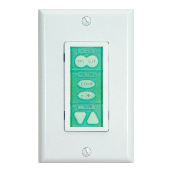
I. Introduction Mounting Screws IR Transmitter IR Learning Window Insert Modules Status LED PixiePlus Board Learning Mode Activation Switch Easy Setup and Configuration The PixiePlus (PXE-DCM+) is a single-gang AV control device. The modular button interface is easily customizable and enables control of almost any display device. The PixiePlus is field-programmed in minutes using IR-learning technology. -
Page 5: Installation Overview
- 1 3-conductor Cable (Required) - 1 Leviton Decora™ wall plate (Required. Match to bezel color.) - 1 Single-Gang Back Box (Optional. SP Controls recommends using a grounded back box) - Additional RS232/IR transmitter for control of additional display devices (Optional,... -
Page 6: Wiring Pixieplus To Display Device
III. Wiring PixiePlus to Display Device Installation IR Emitter to IR Receiver Window Position the clamshell cable assembly at the display device you wish to control. Wire the cable assembly to the PixiePlus using a three- conductor cable (not included). We recom- mend using 18-, 20-, or 22-gauge stranded Connect copper wire cable, such as standard audio... -
Page 7: Pixieplus Installation
Note: You must chose one and only one insert module of each type, i.e. you cannot use two source insert modules and no volume module. Included Insert Modules Customized silkscreened button modules are also available; contact SP Controls for more information. Toggling... - Page 8 Bezel Inserts Pixie Board Be sure the bezel is placed right side up - otherwise it may block the pro- gramming window and Status LED. The SP Controls logo should be in the correct orientation.
- Page 9 IV. PixiePlus Installation cont’d 3. Wire Controller Connect the 3-conductor cable to the captive screw connector on the back of the PixiePlus. Be sure that the wires match the connections on the cable assembly block end - the PixiePlus uses crossover wiring. Wire landing must match landing on cable assembly block at the display device...
- Page 10 IV. PixiePlus Installation cont’d 4. Wire Additional Assemblies to Control Multiple Display Devices (Optional) To control multiple devices, wire each additional PXE- EMIT-232/IR in parallel to the PixiePlus. Each position on the PixiePlus barrier strip must be wired directly to the corresponding position on the PXE-EMIT-232/IR barrier strip.
-
Page 11: Program Pixieplus
(see PixiepPlus installation Section 6 on Page 8). If you are using a device manufactured by Philips, Magnavox, or Koss, please con- sult the SP Controls PXE-DCM Philips Protocol Application Note for special instruc- tions. Visit the support section of our web site to find that document. - Page 12 V. Program PixiePlus cont’d 3. Test Remote and Identify Sweet Spot: Position the remote control a few inches from the IR learning eye (upper right of PixiePlus front). When you press a key on the remote, the PixiePlus status LED should flicker. As you move the remote closer or farther from the receiver window, or move off axis the red flashes will dim and become intermittent.
- Page 13 V. Program PixiePlus cont’d 5. To program a button with a single code: While the PixiePlus is in learning mode, press the button to be programmed to arm it. It should beep once and slowly blink. If the button beeps loudly as soon as you press it, check if the Status LED is solidly lit.
- Page 14 V. Program PixiePlus cont’d The armed key will indicate it is ready to learn the first code by flashing once, paus- ing, flashing once, and so on. Hold the remote control in the sweet spot you found in Step 3. Press and hold the button on the remote for about a second.
- Page 15 V. Program PixiePlus cont’d If the button did not seem to learn correctly, press any other button on the PixiePlus, then press the target button again to rearm it, and repeat the learning procedure. 8. Repeat for Each Button: While still in learning mode, program and verify each button.
-
Page 16: Configuring Special Features
V. Program PixiePlus cont’d Example: You wish to configure the PixiePlus to send a power command to a pro- jector and a separate power command to an amplifier with single press of the Pix- iePlus POWER ON button. To do so, program the PixiePlus POWER ON button with two commands, Power On from the projector remote, and Power On from the amplifier remote. - Page 17 VI. Configuring Special Features cont’d Use of the Inactivity Shutdown Timer requires the DISCRETE POWER ON/POWER OFF keypad module. Configuration of the Inactivity Shutdown Timer requires the VOLUME UP and VOL- UME DOWN keypad module to be inserted. The volume module can be replaced with a blank after the feature is configured.
- Page 18 VI. Configuring Special Features cont’d 2. Security Keylock The Security Keylock locks the PixiePlus during disuse to prevent unauthorized use. It disables the keys on the PixiePlus after POWER OFF is pressed, until a Se- curity Keycode is entered on the standard PixiePlus keypad. If the proper code is not entered, the system cannot be turned on or used.
-
Page 19: Cloning
VI. Configuring Special Features cont’d If more than six keys are entered, the PixiePlus will beep and reset to the previously configured code. 4. After the new Security Keylock has been reconfigured, its new settings must be confirmed. If you do not follow this sequence to store the new settings, any changes you make will be discarded when you leave Security Keylock configuration mode. - Page 20 VII. Cloning cont’d Cloning Procedure 1. Set the recipient to cloning mode. If the PixiePlus has never been programmed, you may set it to cloning mode by pressing and holding any button while applying power. If a PixiePlus has previously been programmed, gently insert a paper clip into the IR Learning aperture of the recipient unit.
-
Page 21: Complete Installation
VII. Cloning cont’d When the units are correctly lined up, the donor PixiePlus will automatically enter cloning mode. Its Status LED will turn solid red and both units will chirp rapidly. 3. Hold the recipient steadily in front of the donor. If the connection is broken (the recipient ceases to chirp), reposition the recipient unit to re-establish communica- tion and the units will continue where they left off. -
Page 22: Operation
IX. Operation Power Power buttons control power on the projector or monitor. The PixiePlus is always on, and its LED backlit buttons remain continually illuminated, unless the Security Keylock is active. Toggling Discrete Source Source button inserts control input selection on the projector or monitor. Toggling Discrete Discrete... -
Page 23: Troubleshooting
Then reseat the buttons, re-attach the bezel, and try entering programming mode again. If this does not correct the problem, please contact SP Controls Technical Support. Operation Problems The PixiePlus does not power the projector/monitor on. -
Page 24: Technical Specifications
If you are using a device manufactured by Philips, Magnavox, or Koss, please con- sult the SP Controls PXE-DCM Philips Protocol Application Note for additional pro- gramming instructions. If you are still unable to control your device, please contact SP Controls Technical Support for further assistance. XI. Technical Specifications Package Type Single-Gang Decora™... -
Page 25: Warranty
There are no obligations or liabilities on the part of the SP Controls Corporation for consequential damages arising out of or in conjunction with the use or performance of these products or other indirect damages with respect to loss of profit, revenue, or cost of removal and/or replacement.
Need help?
Do you have a question about the PixiePlus PXE-DCM PLUS and is the answer not in the manual?
Questions and answers