Subscribe to Our Youtube Channel
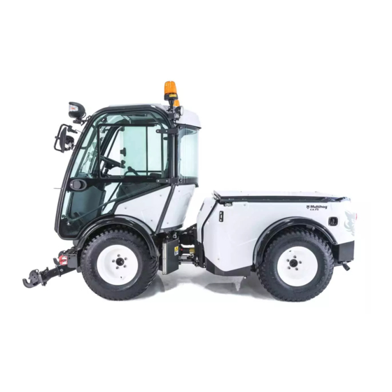
Summary of Contents for Multihog CX75
- Page 2 FIG. 1 Ensure the attachment stands are high enough to clear the load rails on the machine while reversing into position (fig 1). Be careful not to reverse into the attachment while lining load rails up with the attachment frame.
- Page 3 FIG. 2 When the attachment is on the rails ensure the pins supplied are put in the three positons on either side of the load bed. Fig. 2 FIG. 3 Lock pin in place as shown above in Fig. 3 with R- key supplied.
- Page 4 FIG.4 When connecting the attachment hoses to the Auxiliary ports on the rear of the machine note as stated below where each hose goes in Fig. 4 above. 1. (HPCO) The two hoses on the rear LHS highlighted in red are the oil feed and return for the high pressure carry over.
- Page 5 FIG. 5 Plug rear attachment loom into socket on the front of the CX rear chassis. The loom (red) and socket (blue) are shown above in Fig. 5. This supplies power to the solenoids on the valve block on the rear attachment.
- Page 6 FIG. 6 When mounting the front trunk on the cab of the machine, use lifting points shown above in Fig. 6 to lift the attachment safely. Use adequately specified shackles and crane to lift and secure the trunk safely also.
- Page 7 M16 X 120 BOLT, FLAT & SPRING WASHER 5MM WASHER BUSHING TOP 4MM S.S WASHER BUSHING 12MM SPACER BOTTOM 40mm x 20mm Bushing FIG. 7 Attach the Trunk to the Cab using the bolts, spacers and washers supplied as above. Bolt the trunk frame mounting points highlighted in red above in Fig.
- Page 8 FIG. 8 Connect the 6 hoses that run over the cab from the trunk Fig. 8 at the front of the attachment. Each hose is tagged a specific colour (red, yellow & green) and should be connected to the quick release couplers on the front as labelled above in the corresponding colours.
- Page 9 FIG. 9...
- Page 10 Before operating machine ensure that PTO flow has been adjusted correctly. Flow guidelines outlined below. 1. Open machine RH rear chassis panel to gain access to the PTO Needle Valve shown above in Fig. 9.The needle valve is behing the splitter box 2.
- Page 11 FIG. 11 To operate the Trunk attachment, use the Joystick on the armrest shown above in Fig. 11 and follow the guidelines outlined below. 1. (Slew) To slew the trunk from left to right (Yellow Outline) push the joystick forwards and backwards.
- Page 12 LOOM INSTALLATION AND WIRING INSTRUCTIONS FIG. 12 The loom supplied consists of an earth cable, socket for plugging in attachment, 2-pin power supply plug, 6-pin joystick plug and a 15-pin Bucher controller plug. As shown above in Fig. 12, bolt the Earth cable down beside the front RH cab mount. The hole available is currently used for mounting the horn behind the front auxiliary steel pipes.
- Page 13 FIG. 13 Track the cable with the socket for plugging in an attachment down the centre of the front and rear chassis along the hydraulic hoses as shown above in Fig. 13. Fasten socket to front chassis grill frame beside cab air duct using plastic nut as shown above. FIG.
- Page 14 6-pin Joystick plug 15-pin Bucher controller 2-pin plug power supply plug Fig. 15 Note descriptions of the 3 plugs above in Fig. 15 for the next section of loom installation. Fig. 16 Remove RH side panel on the inside of the cab for access. Track cables through the rear of the side panel and neatly along the side of the panel towards back of the seat.
- Page 15 Fig. 17 Remove External panel under cab RH door for installation access also. Fig. 18 Continue routing the 15-pin plug and 2-pin power supply plug along the inside of the cab side panel towards the front. Loop and leave in this position for now.
- Page 16 Fig. 19 Cut slot approx. 140mm to the RHS of the rear mont hole on the side panel as shown above in Fig. 19. Fig. 20 Route wire through cab side panel and bolt panel back into place. Track wire to the back of the seat.
- Page 17 Fig. 21 Bolt armrest attachment to the seat using M8 x 45mm stainless steel bolts and lock nuts. Keep armrest height adjuster accessible. Fig. 22 Track 6-pin plug loom through the back of the armrest and cable tie in place as shown above in Fig.
- Page 18 Fig. 23 Cable tie and sticky back the Joystick loom socket and 6-pin plug neatly under the armrest attachment and out of sight as shown above in Fig. 23. Plug the 6-pin plug into the joystick loom socket. Fig. 24 Bolt the Bucher control unit on the inside of the side panel directly behind the cup holder.Use bolts already there for holding the cup holder in place.
- Page 19 Fig. 25 Plug 15-pin plug into the bucher controller unit. Fig. 26 Plug 2-pin plug for power supply into the spare power supply loom (red) at the front of the panel. One is already in use for the cab power supply port (Blue) Fig. 26. Put external panel back on machine and tighten bolts.

Need help?
Do you have a question about the CX75 and is the answer not in the manual?
Questions and answers
i need to know type of engine oil used oncx75 mulihog