Table of Contents
Advertisement
Quick Links
Advertisement
Table of Contents

Summary of Contents for ADInstruments PowerLab 2/20
- Page 1 A D I n s t r u m e n t s PowerLab /20 Owner’s Guide for PowerLab 2/20 and PowerLab 4/20 models PowerLab 2 20 Input 1 Input 2 ADInstruments Power Output Status Trigger PowerLab 4 20 Input 1...
- Page 2 This document was, as far as possible, accurate at Product: PowerLab 2/20 (ML820); PowerLab 4/20 the time of printing. Changes may have been made (ML840) to the software and hardware it describes since then, though: ADInstruments reserves the right to Hardware: Michael Macknight, Boris Schlensky, alter specifications as required.
-
Page 3: Table Of Contents
Problems: Windows 29 The PowerLab System 3 Computer Requirements 3 C Specifications The Application Programs 4 Other ADInstruments Hardware 4 PowerLab 2/20 Specifications 33 The PowerLab 4 PowerLab 4/20 Specifications 36 The Front Panel 5 The Back Panel 8 Glossary... - Page 4 PowerLab Owner’s Guide...
-
Page 5: Safety Notes
Applicable Safety Standards When used with insulated transducers or ADInstruments isolated front-ends, PowerLab systems are safe for human connection. The ML132 Bio Amp, ML135 Dual Bio Amp, ML408 Dual Bio Amp/Stimulator, ML116 GSR Amp, ML117 BP Amp and ML180 front- ends conform to international safety requirements. - Page 6 PowerLab and the computer. • The PowerLab 2/20 and PowerLab 4/20 are classified as Class I medical equipment, which means that protection against electric shock in the event of a fault relies on a direct connection through the power cable to your building’s earth conductor.
- Page 7 Preventative Inspection and Maintenance Both PowerLab systems and ADInstruments front-ends are maintenance free and do not require periodic calibration or adjustment to ensure medical safety. Internal diagnostic software performs system checks during power up and will report errors if a significant problem is found.
- Page 8 If you so wish, your PowerLab system can be periodically checked for basic medical safety by using an appropriate medical safety testing device. Tests such as earth leakage, earth bond, insulation resistance, patient leakage and auxiliary currents and power cable integrity can all be performed on the PowerLab system without having to remove the covers.
-
Page 9: Overview
Windows or Macintosh computer. This chapter provides an overview of the PowerLab system and describes the basic features, connectors, and indicators of the /20 series PowerLabs: the PowerLab 2/20 and PowerLab 4/20. PowerLab Owner’s Guide... -
Page 10: How To Use This Guide
PowerLab can and cannot do, but this is not a service manual: only an authorised ADInstruments distributor should attempt repairs. If you modify the recording unit yourself, you void any rights you have under warranty. -
Page 11: The Powerlab System
Once the PowerLab transfers the data to the computer, the data are available for display, manipulation, printing, storage, and retrieval. The PowerLab 2/20 has two inputs for recording external signals, the PowerLab 4/20 has four. Computer Requirements Windows •... -
Page 12: The Application Programs
Other ADInstruments Hardware ADInstruments has a range of optional ancillary devices that can be connected to the PowerLab to extend the system’s capabilities. They afford extra signal conditioning and other features, and extend the types of experiments you can conduct and the data you can record. -
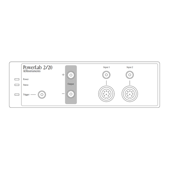
Page 13: The Front Panel
This section describes each of the front panel features. The PowerLab 2/20 has three indicators at the left of the front panel, one BNC connector for the external trigger, two BNC connectors for output, and two BNC connectors (marked Input 1 and Input 2) with two alternative pod (DIN) connectors, for recording external signals. - Page 14 Note that applying more than ± 15 V to the analog inputs can damage the circuitry. The PowerLab 2/20 has two independent analog inputs (marked Input 1 and Input 2), each of which has alternative connectors. The PowerLab 4/20 has four independent analog inputs (marked Input 1 to Input 4), the first two of which have alternative connectors.
- Page 15 Human subjects Pod connectors allow the connection of ADInstruments pods — must not be connected small, low-cost units that provide alternatives to front-ends for directly to the PowerLab.
-
Page 16: The Back Panel
The PowerLab back panel provides the sockets to connect the PowerLab to the computer, front-ends, the power outlet, and so on. This section describes each of the back panel features. The back panels are the same for the PowerLab 2/20 and PowerLab 4/20. Model and serial numbers Earth... - Page 17 You can safely turn on or off, or disconnect or reconnect, a USB- connected PowerLab while the computer remains on, in most cases. The application program (Chart or Scope) must not be running while this occurs, though. Read the details on USB in Chapter 2 of this guide before connecting your PowerLab to your computer using USB.
- Page 18 must be returned for service by qualified service personnel. Do not attempt to replace internal power supply fuses yourself. PowerLab Owner’s Guide...
-
Page 19: Setting Up
C H A P T E R T W O Setting Up This chapter starts with the PowerLab’s internal self-test, then looks at how to connect up your PowerLab to a computer. It discusses the USB connection in some detail. PowerLab Owner’s Guide... -
Page 20: Self-Test
Self-Test Now that you are familiar with some of the features of your PowerLab, you should check that it is working properly before you connect it to your computer. The PowerLab performs a diagnostic self-test each time it is switched on, whether or not it is connected to a computer. -
Page 21: The Usb Connection
If the PowerLab does not seem to be getting power, or the Status indicator flashes red even after restarting, contact your authorised ADInstruments distributor as soon as possible. Do not attempt to repair the PowerLab yourself. If your PowerLab has successfully performed its internal self-test, read on to find out how to connect it to your computer. -
Page 22: Connecting The Powerlab Using Usb
must be no more than 5 metres (16 feet) in length. Thus, no device can be more than 30 metres (98 feet) from the computer. USB lets one plug in and remove devices while the computer is on. It re-enumerates (provides addresses for) devices as they are connected and disconnected, rather than requiring fixed ID numbers. -
Page 23: Usb Connection Rules
PowerLab connection Figure 2–2 Connecting a PowerLab to a USB icon computer with USB. Computer or hub connection B plug A plug USB cable USB Connection Rules 1. Cable length should be less than 5 metres (16 feet) between devices. Devices include USB hubs. - Page 24 Scope is open. Stop sampling and quit the program first before disconnecting a PowerLab from USB. You can safely turn on or off, or disconnect or reconnect, a USB- connected PowerLab while the computer remains on, as long as the application program (Chart or Scope) is off when you do it.
-
Page 25: A Technical Aspects
This provides data transfer rates of up to 800 kB per second, possibly more in some cases. The PowerLab 2/20 has two and the PowerLab 4/20 has four analog inputs, used to record external signals prior to digitising. The outputs of these input amplifiers are multiplexed to a 16-bit ADC (analog-to-... - Page 26 The external trigger input (marked ‘Trigger’ on the front panel) allows either a voltage level or a contact closure to trigger recording. Figure A–1 Block diagram of the PowerLab 2/20. I C Port USB Port Serial Port IEC Mains...
- Page 27 Note that for either mode the trigger signal must be present for at least 5 µs to register as an event. When a trigger event occurs, the trigger indicator light will glow yellow. When set up through software to use a voltage level, a trigger event is registered when the voltage exceeds 2.9 volts.
-
Page 28: The Analog Inputs
(the gain is set through the software range control: the less the range, the more the gain). Inputs 1 and 2 of the PowerLab 2/20 and PowerLab 4/20 can be set by the software to Caution be either single-ended —... - Page 29 ground. Differential signals can only be recorded using a pod connector; the BNC analog inputs on the PowerLabs are all single- ended. Inputs 3 and 4 of the PowerLab 4/20 are single-ended, but can be set by the software to be either positive or negative (inverting or non-inverting).
-
Page 30: Powerlab Accuracy
(say at 20% and 80% of full scale) and recording the signal, you can use the units conversion feature of ADInstruments software to convert and display transducer readings in the appropriate units. This will compensate for any minor inaccuracies in amplifier gain and transducer calibration. - Page 31 2.9 V ± 0.25 V; once on, the trigger turns off at 1.8 V ±0.25 V, giving a hysteresis voltage of 1.1 V. The external trigger input draws 2.2 mA at 5 V and 5.5 mA at 10 V. The trigger input is optically isolated when set up for a voltage level, as shown in Figure A–5.
-
Page 32: The Analog Output
The Analog Output The analog outputs provide computer-controlled variable outputs (±10 V) that can be used with the Chart and Scope applications either directly as a stimulator, or to control peripheral devices. All stimulation voltage is generated by the PowerLab via the output sockets on the front of the PowerLab (marked ‘Output’), giving positive, negative, or differential stimuli, depending on the sockets used and the software settings. -
Page 33: I 2 C Expansion Port
The pin assignments for the C port. Pod Connectors The pod connectors on Inputs 1 and 2 of the PowerLab 2/20 and PowerLab 4/20 are 8-pin DIN connectors. Pod connectors allow the connection of ADInstruments pods — small, low-cost units that provide alternatives to front-ends for specific tasks, for use with... -
Page 34: Serial Port
handle transducers directly unless the transducers are so labelled (unsuitable transducers will give a very weak signal). Transducers designed for direct connection can be provided with power and control, since the pod connectors provide some functions of the I output as well as alternative analog inputs to the BNC connectors. Do not attempt to record from both the BNC and pod connectors for an input at the same time, or the signals will compete. -
Page 35: B Troubleshooting
If none of the solutions here or in the software guide appears to help, then consult your ADInstruments distributor. Problems: Macintosh Most problems that users encounter are connection problems. - Page 36 The computer refuses to boot with the PowerLab connected, or the computer can’t find the PowerLab The PowerLab is off or the power is switched off at the wall, the power cable is not connected firmly, or a fuse has blown. •...
-
Page 37: Problems: Windows
If not, then the software may have a serious fault, and may need to be reinstalled, or the PowerLab may need repair. Consult your ADInstruments distributor. When Windows starts up, it doesn’t recognise the PowerLab This should happen only the first time PowerLab hardware is connected to the computer. - Page 38 • Ensure that the cable is firmly attached at both ends and try again. If there is still a problem, try a new cable. The PowerLab has an internal problem or has ‘hung’. • Turn everything off, and then after at least five seconds turn the PowerLab back on again.
- Page 39 • USB needs a USB 1.1-compliant PC with Windows 98, Me, 2000 or later; it simply will not work with earlier operating systems, such as Windows 95 or Windows NT 4. The computer hangs up while recording, or there is data loss A poor connection between PowerLab and computer, or bad cable.
- Page 40 PowerLab Owner’s Guide...
-
Page 41: C Specifications
A P P E N D I X Specifications PowerLab 2/20 Specifications Input Number of inputs: Input configuration: Single-ended or differential (the latter only through the pod connectors) ±2 mV to ±10 V full scale in 12 steps Amplification ranges: ±... - Page 42 DC drift: Software-corrected CMRR (differential): 96 dB @ 50 Hz (typical) Input crosstalk: –110 dB typical <2.4 µV Input noise: referred to input, DC to 20 kHz Pod connectors: Combine power, I C and single-ended or differential analog input signals on one connector, support pods, particular transducers, etc.
- Page 43 ±200 mV to ±10 V full scale in six steps Output ranges: ± 10 V ± 5 V ± 2 V ± 1 V ± 500 mV ± 200 mV External Trigger +2.9 V ±0.25 V or contact closure Trigger threshold: (software-selectable) 1.1 V (turns off at +1.8 V ±0.25 V) Hysteresis:...
-
Page 44: Powerlab 4/20 Specifications
Maximum power needs: 18 VA (full complement of front-ends and pods) 0 to 35 °C, 0 to 90% humidity (non- Operating temperature range: condensing) PowerLab 4/20 Specifications Input Number of inputs: Input configuration: Single-ended or differential (the latter only through the pod connectors on Inputs 1 & 2) ±2 mV to ±10 V full scale in 12 steps Amplification ranges: ±... - Page 45 Pod connectors: Combine power, I C and single-ended or differential analog input signals on one connector, support pods, particular transducers, etc. ±5 V regulated Supply voltage: Maximum current: 50 mA per pod port Communications: 2-wire I Signal input: Positive and negative analog inputs Connector type: 8-pin DIN.
- Page 46 Maximum power needs: 18 VA (full complement of front-ends and pods) 0 to 35 °C, 0 to 90% humidity (non- Operating temperature range: condensing) ADInstruments reserves the right to alter these specifications at any time. PowerLab Owner’s Guide...
-
Page 47: Glossary
Glossary This covers terms used in this owner’s guide, volts. Inputs can be either single-sided or those for ADInstruments front-ends, and the differential (the latter only in the case of the user’s guides for ADInstruments software. pod connectors). General and specific computer terminology should be covered in the material that came analog output. - Page 48 bus. A data-carrying electrical pathway. envelope form. The overall shape of a signal, outlined by the minimum and maximum Chart. An application supplied with a recorded values. Often used to display PowerLab that emulates a multi-channel quickly changing signals. chart recorder, with other powerful options. (Macintosh and Windows versions differ.) excitation voltage.
- Page 49 200 kHz for PowerLabs. inputs (Inputs 1 and 2 on the PowerLab 2/20 and PowerLab 4/20). Pods can connect to high-pass filter (HPF). A filter that passes them, and they can also provide power and high-frequency signals, but filters low ones,...
- Page 50 with a PowerChrom recording unit. serial. A connection protocol for sending (Macintosh and Windows versions are very information sequentially, one bit at a time, similar.) over a single wire. PowerChrom System. The system consists of TChart. A simplified version of the Chart a PowerChrom recording unit and the program once used for teaching.
-
Page 51: Index
Index ADC (analog-to-digital converter) 17 equipotential connection 9 – ADInstruments contacts ii error patterns 12 – – – – analog input 6 external trigger 7 analog output 7 analog-to-digital converter 17 – front panel 5 front-ends 4 – back panel 8... - Page 52 Scope 4 – self-test 12 serial port 9 Status indicator 6 storage vii technical specifications – PowerLab 2/20 33 – PowerLab 4/20 36 transducers 4 trigger 7 Trigger indicator 6 cables 15 – connection 13 – connection rules 15 –...
-
Page 53: Licensing & Warranty Agreement
Licensing & Warranty Agreement Extent This Agreement is between ADInstruments Pty If problems arise with an ADI product, ADI will Ltd [‘ADI’] and the purchaser [‘the Purchaser’] of make all reasonable efforts to fix them. This service any ADI product — software, hardware, or both —... - Page 54 Hardware Warranty Technical Support ADI warrants that the hardware purchased by the Once a customer registration form has been filled Purchaser shall be free of defects in material and out and sent in, the Purchaser is entitled to free workmanship for one year from its date of technical support for any ADI product for one year purchase.
Need help?
Do you have a question about the PowerLab 2/20 and is the answer not in the manual?
Questions and answers