Advertisement
Quick Links
Amplifier-separated Type Inductive Proximity Sensor
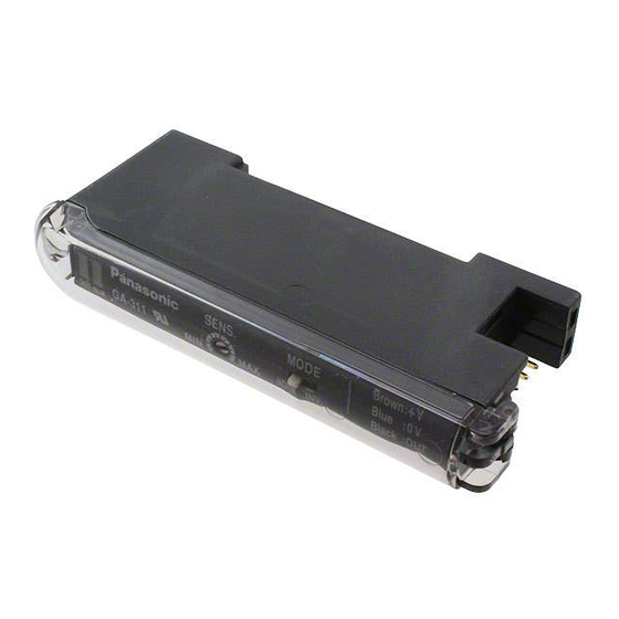
Amplifier GA-311 Sensor head GH- SE
Thank you very much for purchasing Panasonic products. Please read this
Instruction Manual carefully and thoroughly for the correct and optimum
use of this product. Kindly keep this manual in a convenient place for quick
reference.
Never use this product as a sensing device for personnel protection.
In case of using sensing devices for personnel protection, use products
which meet laws and standards, such as OSHA, ANSI or IEC etc., for
personnel protection applicable in each region or country.
1
SPECIFICATIONS
Sensor head
Typ e
Item
Model No.
GH-2SE
Applicable amplifier
Stable sensing range (Note 1)
0 to 0.6mm
Max. operation distance (Note 1)
1.2mm
Standard sensing object
Iron 5 5 t1mm
Hysteresis (Note 2)
0.07mm or less
Protection
IP50 (IEC)
Ambient temperature
Ambient humidity
Temp. characteristic (Note 3)
Within
7%
Enclosure:
SUS303
Material
Sensing part:
PVC
Connector attached oil resistant high frequency coaxial cable, 3m long
Cable (Note 4)
[Spatter resistant cable for GH-F8SE (Outer shield: Fluorine resin)]
Weight
15g approx.
Notes: 1)
The stable sensing range represents the sensing range for which the sensor
can satisfy all the given specifications with the standard sensing object.
The maximum operation distance represents the maximum distance for
which the sensor can detect at +20
Usage within the stable sensing range is recommended for accurate
sensing applications.
2)
Value is given for the stable sensing range.
3)
The value represents the variation in the operation distance, that has been
set within the stable sensing range at +20 , for an ambient temperature
drift from 0 to +55 . (The value is for sensor head on its own.)
4)
The length of the sensor head cable cannot be changed.
Amplifier
T ype
Item
Supply voltage
12 to 24V DC 10 % Ripple P-P10 % or less
Current consumption
NPN open-collector transistor
Maximum sink current: 100mA
Output
Applied voltage: 30V DC or less (between output and 0V)
Residual voltage: 1V or less [at 100mA (Note 1) sink current]
Output operation
Normally open / closed Selectable with the operation mode switch
Short-circuit protection
Max. response frequency
Operation indicator
Orange LED (lights up when the output is ON)
Disconnection alarm indicator
Red LED (lights up when the sensor head is disconnected or mis-contacted)
Sensitivity adjuster
-10 to +60
if 8 to 16 units are connected in cascade: -10 to +45 ) (No dew con-
Ambient temperature
densation or icing allowed), Storage: -20 to +70
Ambient humidity
Temp. characteristic (Note 2)
Material
Enclosure: Heat-resistant ABS, Case cover: Polycarbonate
Weight
Notes: 1)
50mA, if five, or more, amplifiers are connected in cascade.
2)
The value represents the variation in the operation distance, that has been
set within the stable sensing range at +20 , for an ambient temperature
drift from 0 to +55 . (The value is for amplifier on its own.)
3)
The cable for amplifier connection is not supplied as an accessory. Make
sure to use the optional quick-connection cable given below.
Main cable (3-core): CN-73-C1 (cable length 1m), CN-73-C2 (cable length 2m)
CN-73-C5 (cable length 5m)
Sub-cable (1-core) : CN-71-C1 (cable length 1m), CN-71-C2 (cable length 2m)
CN-71-C5 (cable length 5m)
Ramco National
INSTRUCTION MANUAL
MJE-GA311 No.0034-54V
WARNING
Cylindrical type
GH-3SE
GH-5SE
GH-8SE
GA-311
0 to 0.8mm
0 to 1.0mm
0 to 2.0mm
1.8mm
2.4mm
4.0mm
Iron 10 10 t1mm
0.05mm or less
0.04mm or less
IP67 (IEC), IP67g (JEM)
-10 to +60 , Storage: -20 to +70
35 to 85% RH, Storage: 35 to 85% RH
Within
5%
Within
4%
Enclosure:
Enclosure:
Enclosure:
SUS303
SUS303
SUS303
Sensing part:
Sensing part:
Sensing part:
ABS
PAR
ABS
35g approx.
40g approx.
constant ambient temperature.
GA-311
25mA or less
Incorporated
3.3kHz
18-turn potensiometer
(if 4 to 7 units are connected in cascade: -10 to +50 ,
35 to 85% RH, Storage: 35 to 85% RH
Within
5%
15g approx.
2
CAUTIONS
This product has been developed / produced for industrial use.
Make sure that the power supply is off while wiring or adding the units.
Take care that wrong wiring will damage the sensor.
Verify that the supply voltage variation is within the rating.
In case noise generating equipment (switching regulator, inverter motor,
etc.) is used in the vicinity of this product, connect the frame ground
(F.G.) terminal of the equipment to an actual ground.
If power is supplied from a commercial switching regulator, ensure that
the frame ground (F.G.) terminal of the power supply is connected to an
actual ground.
Do not use during the initial transient time (0.5 sec.) after the power
supply is switched on.
Do not run the wires together with high-voltage lines or power lines or put
them in the same raceway. This can cause malfunction due to induction.
Be sure to use the optional quick-connection cable for amplifier
connection. Furthermore, extension up to 100m (50m: 5 to 8 units are
connected in cascade, 20m: 9 to 16 units are connected in cascade) is
possible with 0.3mm
make the wiring as short as possible.
Take care that when the cable is extended, the residual voltage rises.
Do not shorten or lengthen the sensor head cable.
This sensor is suitable for indoor use only.
Spatter-resistant type
GH-F8SE
Do not use the sensor at places having intense vibrations, as this can
cause malfunction.
Take care that the sensor does not come in direct contact with water, oil,
grease, organic solvents, such as, thinner etc., or strong acid, and alkaline.
Make sure that the sensing end is not covered with metal dust, scrap or
spatter. It will result in malfunction.
Take care that stress by forcible bending or pulling is not applied directly
to the sensor head cable joint.
3
MOUNTING
Enclosure:
SUS303
Sensing part:
Be sure to use a sensor head and amplifier as a set.
Fluorine resin
Mounting of amplifier
How to mount the amplifier
55g approx.
Fit the rear part of the mounting section of the
amplifier on a 35mm width DIN rail.
Press down the rear part of the mounting section
of the unit on the 35mm width DIN rail and fit the
front part of the mounting section to the DIN rail.
How to remove the amplifier
Push the amplifier forward.
Lift up the front part of the amplifier to remove it.
Note:
Take care that if the front part is lifted without pushing the amplifier forward, the
hook on the rear portion of the mounting section is likely to break.
Connection of sensor head
Connection method
Insert the the sensor head connector into
the connector inlet till a click is felt.
Fit the cover on the connector.
Disconnection method
Pressing the projection on the sensor
head connector, pull out the connector.
Note:
Take care that if the connector is pulled out without pressing the projection, the pro-
jection may break. Do not use a sensor head connector whose projection has bro-
ken. Furthermore, do not pull by holding the cable, as this can cause a cable-break.
Mounting of sensor head
Mounting with a set screw
The tightening torque
for mounting should be
as given right.
Furthermore, be sure
to use a set screw with
a cup-point end.
Note:
Do not tighten it with excessive strength.
Influence of surrounding metal
The surrounding metal
will affect the sensing
performance. Keep the
minimum
specified in the table
right.
www.PanasonicSensors.com
2
or more, cable. However, in order to reduce noise,
Set screw (M3)
(Cup-point end)
Model No.
A
GH-2SE
GH-3SE
GH-5SE
GH-8SE
GH-F8SE
B
distance
35mm width DIN rail
Sensor head
connector part
Projection
Cover
A mm
Tightening torque
3 or more
0.17N m
4 or more
0.17N m
5 or more
0.78N m
5 or more
0.59N m
Model No.
B mm
GH-2SE
3
GH-3SE
4
GH-5SE
5
GH-8SE
9
GH-F8SE
1-800-280-6933
Advertisement

Related Manuals for Panasonic GA-311


Summary of Contents for Panasonic GA-311
- Page 1 MJE-GA311 No.0034-54V etc.) is used in the vicinity of this product, connect the frame ground Thank you very much for purchasing Panasonic products. Please read this (F.G.) terminal of the equipment to an actual ground. Instruction Manual carefully and thoroughly for the correct and optimum If power is supplied from a commercial switching regulator, ensure that use of this product.
- Page 2 2431-1 Ushiyama-cho, Kasugai-shi, Aichi, 486-0901, Japan connector, pull out the connector. Phone: +81-568-33-7861 FAX: +81-568-33-8591 Remove the amplifiers. About our sale network, please visit our website. PRINTED IN JAPAN © Panasonic Industrial Devices SUNX Co., Ltd. 2012 Ramco National www.PanasonicSensors.com 1-800-280-6933...
Need help?
Do you have a question about the GA-311 and is the answer not in the manual?
Questions and answers