Table of Contents
Advertisement
Advertisement
Table of Contents

Summary of Contents for Westpro Westinghouse WH3250 Series
- Page 2 No part of this publication may be reproduced or used in any form by any means – graphic, electronic or mechanical, including photocopying, recording, taping or information storage and retrieval systems – without the written permission of Westpro Power Systems, LLC.
-
Page 3: Table Of Contents
Safety Defi nitions .............................1-1 Safety Symbol Defi nitions ..........................1-1 General Safety Rules ............................1-2 WARRANTY ................................2-1 Westpro Power Systems “Three Year” Limited Warranty ..................2-1 Westpro’s Responsibility ..........................2-1 Owner’s Responsibility ..........................2-1 Product Warranty Applications and Product Warranty Periods ..............2-1 Consumer Application .........................2-1 Commercial Application ........................2-1... - Page 4 TABLE OF CONTENTS Oxygenated Fuel Types ..........................7-2 Ethanol (Ethyl or Grain Alcohol) ......................7-2 Methanol (Methyl or Wood Alcohol) ....................7-2 MTBE (Methyl Tertiary Butyl Ether) .....................7-2 Adding Gasoline to the Fuel Tank ......................7-2 Engine Oil ................................7-3 Engine Oil Specifi cation ..........................7-3 Low Oil Protection ............................7-3 Checking Engine Oil ..........................7-3 Adding Engine Oil ............................7-4...
-
Page 5: Safety
SAFETY SAFETY DEFINITIONS SAFETY SYMBOL DEFINITIONS The words DANGER, WARNING, CAUTION and NOTICE are used throughout this manual to highlight important information. Be certain that the meanings of Symbol Description these alerts are known to all who work on or near the equipment. -
Page 6: General Safety Rules
SAFETY GENERAL SAFETY RULES WARNING Gasoline and gasoline vapors are DANGER extremely fl ammable and explosive Never use the generator in a location under certain conditions. that is wet or damp. Never expose the • Always refuel the generator outdoors, generator to rain, snow, water spray or in a well-ventilated area. - Page 7 SAFETY WARNING WARNING Never operate the generator if powered California Proposition 65 items overheat, electrical output drops, The engine exhaust from this product there is sparking, fl ames or smoke contains chemicals known to the state coming from the generator, or if the of California to cause cancer, birth receptacles are damaged.
- Page 8 SAFETY This Page Intentionally Left Blank...
-
Page 9: Warranty
You may register on-line at www.westpropower.com, by automated phone at 1-855-944-3571, or by fi lling out and returning to WESTPRO the warranty registration card supplied with your generator. Registering your product confi rms your warranty coverage and provides a direct link between you and WESTPRO if we fi nd it necessary to contact you. -
Page 10: Non-Warrantable Applications
This warranty gives you specifi c legal rights. You also have other rights from state to state. WESTPRO’S ONLY LIABILITY SHALL BE THE REPAIR OR REPLACEMENT AS STATED ABOVE. IN NO EVENT SHALL WESTPRO BE LIABLE FOR ANY INCIDENTAL OR CONSEQUENTIAL DAMAGES, EVEN IF SUCH DAMAGES ARE A DIRECT RESULT OF WESTPRO’S NEGLIGENCE. -
Page 11: Emissions Control Warranty
Westpro Power Systems, LLC recommends that you retain all receipts covering maintenance on your outdoor equipment, but Westpro Power Systems, LLC cannot deny warranty solely for the lack of receipts or your failure to ensure the performance of all scheduled maintenance. -
Page 12: Defects Warranty Requirements
Westpro Power Systems, LLC will not be liable to warrant failures of warranted parts caused by the use of a non-exempted add-on or modifi ed part. -
Page 13: Warranted Parts
Fuel hose Fuel hose clamps Tethered fuel cap Carbon canister Vapor lines QUESTIONS: If you have any questions regarding your emissions warranty rights and responsibilities you should contact Westpro Power Systems, LLC at: Phone: (855) 944-3571, toll free Email: service@westinghousepowerproducts.com... - Page 14 EMISSIONS CONTROL WARRANTY This Page Intentionally Left Blank...
-
Page 15: Specifications
SPECIFICATIONS SPECIFICATIONS Table 3-1: Westpro Portable Generator Specifi cations WH4500 WH5500 WH6000 WH6500E WH7000/E WH7500E WH3250 GENERATOR Series Series Series Series Series Series Series POWER Rated [watts] 3250 4500 5500 6000 6500 7000 7500 (+/-10% under load) Maximum [watts] 3750... -
Page 16: Bolt And Fastener Torque Information
SPECIFICATIONS BOLT AND FASTENER TORQUE INFORMATION Table 3-2: Torque Values Torque Values Component-Specifi c Fastener Fastener Size ft-lb N·m Alternator End Cover Bolts M5 x 0.75 x 12 Alternator Housing Bolts M10 x 1.25 x 80 Axle Bracket Bolts M8 x 1.0 x 16 Brush Assembly Bolt M5 x 0.75 x 16 Carbon Canister Bracket Bolts... -
Page 17: Wiring Diagrams
SPECIFICATIONS WIRING DIAGRAMS WH3250 Series Figure 3-1 – WH3250 Series Wiring Diagram... -
Page 18: Wh4500 Series, Wh5500 Series
SPECIFICATIONS WH4500 Series, WH5500 Series Figure 3-2 – WH4500 Series, WH5500 Series Wiring Diagram... -
Page 19: Wh6000 Series
SPECIFICATIONS WH6000 Series Figure 3-3 – WH6000 Series Wiring Diagram... -
Page 20: Wh6500E Series
SPECIFICATIONS WH6500E Series Figure 3-4 – WH6500E Series Wiring Diagram... -
Page 21: Wh7000E Series
SPECIFICATIONS WH7000E Series Figure 3-5 – WH7000E Series Wiring Diagram... -
Page 22: Wh7500E Series
SPECIFICATIONS WH7500E Series Figure 3-6 – WH7500E Series Wiring Diagram... -
Page 23: Components
COMPONENTS GENERAL GENERATOR COMPONENTS Figure 4-1 1 - Engine Control Switch: Turns the engine on 5 - Battery: For electric start models only. and off. 6 - Oil Fill Plug/Dipstick: Must be removed to 2 - Fuel Cap: Close until clicking sound is heard. add and check oil. - Page 24 COMPONENTS Figure 4-2 1 - Fuel Gauge: Indicates fuel level. 6 - Carbon Canister: Model numbers followed by a “C” will be equipped with a carbon 2 - Fuel Shutoff Valve: Controls the fl ow of fuel canister. See Removing Fine Inside Air Filter to the engine.
-
Page 25: Control Panel Features
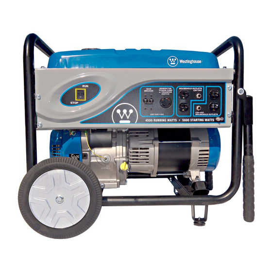
COMPONENTS CONTROL PANEL FEATURES Figure 4-3 – Control Panel Features 1. Engine Control Switch (RUN/STOP for 6. 20-Amp Circuit Breakers: Each circuit Manual Start Units): breaker limits the current that can be delivered through the 120-volt duplex outlets RUN - In the RUN position, the switch to 20 amps. - Page 26 COMPONENTS This Page Intentionally Left Blank...
-
Page 27: Preparing For Service
PREPARING FOR SERVICE TRANSPORTING GENERATOR WARNING ANYONE using or servicing this WARNING generator must read, understand Hot engine or exhaust system can and follow all safety and operation cause serious burns or fi res. Let instructions provided in this generator cool completely before manual. - Page 28 PREPARING FOR SERVICE This Page Intentionally Left Blank...
-
Page 29: Service Repair Time Analysis
SERVICE REPAIR TIME ANALYSIS SERVICE REPAIR TIME ANALYSIS AND FLAT RATE SCHEDULE WH5500 WH3250 Series Series Electric WH6000 WH7000 WH4500 Start Operation Series Series Series Models (min.) (min.) (min.) (min.) ELECTRICAL Alternator Complete Battery – – – Brush Assembly Charging Coil Assembly Control Panel Assembly Flash the Field Ignition Coil... - Page 30 SERVICE REPAIR TIME ANALYSIS WH3250 WH5500 Series Series Electric WH7000 WH4500 WH6000 Start Series Operation Series Series Models (min.) (min.) (min.) (min.) FUEL & EXHAUST Carbon Canister (with bracket) (CARB Emission Equipment) Carbon Canister T ube (CARB Emission Equipment) Exhaust Pipe (CARB Emission Equipment) Fuel Gauge Vapor Line...
-
Page 31: Maintenance
MAINTENANCE MAINTENANCE CAUTION Before performing maintenance Avoid skin contact with engine oil or on the generator, review Safety on gasoline. Prolonged skin contact with page 1-1 and the following safety engine oil or gasoline can be harmful. messages. Frequent and prolonged contact with engine oil may cause skin cancer. -
Page 32: Fuel
MAINTENANCE Oxygenated Fuel Types FUEL Ethanol (Ethyl or Grain Alcohol) Do not use gasoline containing more than 10% ethanol DANGER by volume, as this may cause starting or performance Fuel and fuel vapors are extremely problems. Gasoline containing ethanol may be fl... -
Page 33: Engine Oil
MAINTENANCE Low Oil Protection The generator engine is protected from low lubrication failure by an oil shutdown switch. This switch prevents the ignition system from operating until suffi cient oil is added to the crankcase. When the engine shuts down due to low oil level: The engine control switch will remain in the RUN position. -
Page 34: Adding Engine Oil
MAINTENANCE 6. Check oil level: When checking the engine oil, remove the oil fi ll plug/dipstick and wipe it clean. Thread the oil fi ll plug/dipstick all the way back in, and then remove and check the oil level on the oil fi ll plug/dipstick. Acceptable Oil Level –... -
Page 35: Air Filter Maintenance
MAINTENANCE 9. Fill crankcase with oil following the steps outlined in 2. Move the generator to a fl at, level surface. Adding Engine Oil on page 7-4. 3. Unclip the clips on the top and bottom of the air fi lter cover (see Figure 7-8) and remove the air fi lter NOTICE cover. - Page 36 MAINTENANCE 5. Remove the gray fi ne inside air fi lter (see Figure 9. Dry the air fi lter elements by again applying a slow 7-10). fi rm squeezing action. 10. Once the air fi lters are dry, coat the air fi lters with clean engine oil (see Figure 7-11).
-
Page 37: Cleaning The Fuel Sediment Bowl
MAINTENANCE 14. Install the air fi lter cover by clipping the clips on the 5. Clean the sediment bowl, O-ring and screen (see top and bottom of the air fi lter assembly (see Figure Figure 7-15). 7-13). Figure 7-15 1 - Sediment Bowl 3 - Screen 2 - O-Ring 6. - Page 38 MAINTENANCE 7. Inspect the spark plug for: Cracked or chipped insulator Excessive wear Incorrect spark plug gap (outside the acceptable limit of 0.028 – 0.031 in. [0.70 – 0.80 mm]) (see Figure 7-18). If the spark plug fails any one of the conditions listed above, replace the plug with a Champion RN9YC plug or equivalent.
-
Page 39: Cleaning The Spark Arrestor
MAINTENANCE CLEANING THE SPARK CHECKING AND ADJUSTING ARRESTOR VALVE LASH Check and clean the spark arrestor after every 100 hours of use or 6 months. CAUTION 1. Stop the generator and let it cool for several Checking and adjusting valve lash minutes if running. -
Page 40: Governor Adjustment
MAINTENANCE 6. Insert a feeler gauge between the rocker arm and GOVERNOR ADJUSTMENT the push rod and check for clearance (see Figure 7-21). See Table 7-2 for valve lash specifi cations. 1. Start the engine and run the engine at full throttle with no load. -
Page 41: Battery Service
MAINTENANCE 3. Tip the battery forward slightly to access battery BATTERY SERVICE cables. To ensure the battery remains charged, the generator 4. Disconnect the black negative (-) battery cable from should be started every 2 to 3 months and run for the battery fi... -
Page 42: Cleaning The Generator
MAINTENANCE Clean All Alternator Cooling Air Inlets and Exhaust CLEANING THE GENERATOR Ports – Make sure the cooling air inlets and exhaust Inspect the generator regularly and clean as required. ports of the alternator are free of any debris and obstructions. -
Page 43: Storage
MAINTENANCE STORAGE WARNING Never store a generator with fuel in the tank indoors or in a poorly ventilated area where the fumes can come in contact with an ignition source such as a: 1) pilot light of a stove, water heater, clothes dryer or any other gas appliance;... - Page 44 MAINTENANCE This Page Intentionally Left Blank 7-14...
-
Page 45: Troubleshooting
Only use OUTSIDE and NEVER use inside a far away from windows, home or garage, EVEN doors and vents. IF doors and windows are open. OTE: For all dealer service inquiries, call (855) 944-3571 or e-mail service@westpro.com. -
Page 46: Electrical Diagnostics
TROUBLESHOOTING ELECTRICAL DIAGNOSTICS 240V Circuit Check 120V Circuit Check General Electrical Check (No Output OR (No Output OR Voltage Out of Spec) Voltage Out of Spec) Conduct This Check Only When Conduct This Check Only When Check for T ripped Master Breaker Directed by General Electrical Check Directed by General Electrical Check Resolve Overload Problem to Ensure Safe Operation... - Page 47 TROUBLESHOOTING Resistance Range Specification (Ω) WH5500 Series WH6000 Series Electric WH3250 WH4500 WH7000 Start Measure Resistance Winding Series Series Series Models Brown White Stator-X 1.1 - 1.5 0.5 - 0.7 Stator-Y Blue Green White 0.6 - 0.8 AVR Tap Brown† Blue†...
- Page 48 TROUBLESHOOTING EXCITER & AVR TAP CONNECTOR* STATOR-X BRUSH ASSEMBLY WINDING Blue Green White EXCITER AVR TAP WINDING WINDING Blue White TERMINAL BLOCK *view looking into White female connector Gray from alternator 5-9 mm STATOR-Y Black WINDING White (2 wires) Gray (2 wires) Red (2 wires) Black (2 wires) ROTOR...
-
Page 49: Engine Diagnostics
TROUBLESHOOTING ENGINE DIAGNOSTICS Engine Starts Engine Fails to Crank Engine Fails to Start Engine Runs Rough Then Shuts Down Using Electric Starter Check Recoil for Check Oil Level Check Fuel Level Check Fuel Level Mechanical Binding Check Fuel Level Check Fuel Quality Check Fuel Quality Check Battery Voltage Higher than 12.5 Volts =... - Page 50 TROUBLESHOOTING This Page Intentionally Left BlanK...
-
Page 51: Service And Disassembly
SERVICE AND DISASSEMBLY CONTROL PANEL Figure 9-1 Screws: Tighten to 35 in-lb (4 N·m). Engine Control Switch RUN/STOP – Manual Start Models Front Control Panel Assembly START/RUN/STOP – Electric Start Models Hour Meter – If equipped Diode Main Circuit Breaker 10 - Fuse: 5-Amp –... -
Page 52: Alternator
SERVICE AND DISASSEMBLY ALTERNATOR View A Figure 9-2... - Page 53 SERVICE AND DISASSEMBLY Bolts 10 - Front Engine Adapter End Cover 11 - Bolt Bolt 12 - Stator Assembly Bolt 13 - Bolt 14 - Rotor Assembly Voltage Regulator Brush Assembly: Before removing rotor and 15 - Rotor Bolt stator, remove the brush assembly. When installing 16 - Exciter Winding Connector the brush assembly, tighten to 18 in-lb (2 N·m).
-
Page 54: Engine And Alternator
SERVICE AND DISASSEMBLY ENGINE AND ALTERNATOR Figure 9-3 1 - Rotor Bolt: Apply oil to threads before 5 - Stator Assembly installing. 6 - Front Engine Adapter 2 - Lock Washer 7 - Engine Assembly 3 - Flat Washer 8 - Frame Assembly 4 - Rotor Assembly 9 - Shock Mounts... -
Page 55: Fuel Tank System
SERVICE AND DISASSEMBLY FUEL TANK SYSTEM WARNING Fuel and its vapors are extremely fl ammable and explosive under certain conditions. • Only refuel the generator outdoors, in a well-ventilated area. • Never enclose the generator in any structure. • Keep generator at least 6 feet (2 m) away from buildings, other equipment and combustible materials during operation. -
Page 56: Exhaust Control System
SERVICE AND DISASSEMBLY EXHAUST CONTROL SYSTEM WARNING The muffl er becomes very hot during operation and remains hot for some time after stopping the engine. • Never touch hot surfaces and avoid hot gases. • Let engine cool before storing the generator indoors. to tank Figure 9-5 1 - Spark Arrester: Tighten to 8 in-lb (1 N·m). -
Page 57: Carburetor
SERVICE AND DISASSEMBLY CARBURETOR WARNING Fuel and its vapors are extremely fl ammable and explosive under certain conditions. • Only refuel the generator outdoors, in a well-ventilated area. • Never enclose the generator in any structure. • Keep generator at least 6 feet (2 m) away from buildings, other equipment and combustible materials during operation. -
Page 58: Electric Starting System (Electric Start Models)
SERVICE AND DISASSEMBLY ELECTRIC STARTING SYSTEM (ELECTRIC START MODELS) Figure 9-7 1 - Starter Mounting Bolts 4 - Battery 2 - Starter Solenoid: Tighten solenoid terminal nut 5 - Red Positive (+) Battery Cable to 53 in-lb (6 N·m). 6 - Black Negative (-) Battery Cable 3 - Electric Starter: Move the engine control switch to the START position to operate starter. -
Page 59: Recoil Starter
SERVICE AND DISASSEMBLY RECOIL STARTER Figure 9-8 OTE: There are no serviceable components for the recoil starter. Replace the recoil as an assembly. 1 - Blower Housing 3 - Bolts: Remove the bolts to replace the starter. 2 - Recoil Starter: Install the recoil handle in the position shown. -
Page 60: Fan Cover
SERVICE AND DISASSEMBLY FAN COVER Figure 9-9 1 - Cooling Fan: Install by aligning the holes on 3 - Flywheel Nut: Hold the fl ywheel from turning the fan with the holes on the fl ywheel. Inspect and tighten the nut to 77 ft-lb (105 N·m). the fan blades for wear or damage. -
Page 61: Wheel, Leg And Handle Assembly
SERVICE AND DISASSEMBLY WHEEL, LEG AND HANDLE ASSEMBLY Figure 9-10 Handle Bumper Hairpin Clips Shock Mount Foot Pad Battery (Electric Start Models) Foot Wheel Handle Grips Axle Pin 10 - Handles 9-11... - Page 62 SERVICE AND DISASSEMBLY This Page Intentionally Left Blank 9-12...
Need help?
Do you have a question about the Westinghouse WH3250 Series and is the answer not in the manual?
Questions and answers