Table of Contents
Advertisement
Advertisement
Table of Contents

Related Manuals for Harris NetWave


Summary of Contents for Harris NetWave
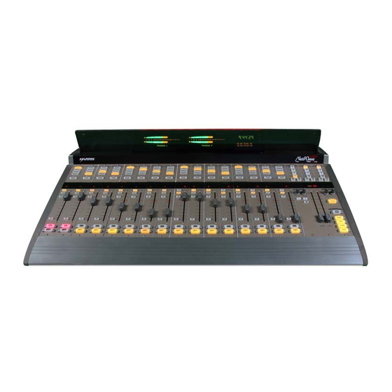
- Page 1 Broadcast Console 8-input console: 99-1600-08 16-input console: 99-1600-16 24-input console: 99-1600-24 Operations & Technical Manual PRE75-54 PRE75-54 PRE75-54 PRE75-54 PRE75-54 Revision A • 6/06 Broadcast Communications Division www.broadcast.harris.com...
- Page 2 H A R R I S C O R P O R A T I O N Revision A • 6/06...
-
Page 3: Table Of Contents
Headphone Distribution Amp ..... 6-3 Basic Peripheral Logic Example ....2-28 ESE/SMPTE Master Clock ......6-4 Complex Peripheral Logic Example ..2-29 NetWave Upgrade Kits ........ 6-5 VistaMax Network Connections ....2-30 Mic Remote Panel Cables ......6-6 3 - USING NETWAVE INDEX Console Overview ......... -
Page 4: Ce Declaration Of Conformity
Declaration of Conformity H A R R I S C O R P O R A T I O N Revision A • 6/06... -
Page 5: Safety Instructions
Safety Instructions 1. R R R R R ead A ead A ead All Instr ead A ll Instr ll Instr ll Instruc uc uc uc uctions tions tions tions..Read all safety and operating 16. P P P P P r r r r r o o o o o duc duct and C t and C t and C... - Page 6 H A R R I S C O R P O R A T I O N Revision A • 6/06...
-
Page 7: Introducing Netwave
NetWave’s capabilities, read through the chapters • 48-volt Supply: an in-line supply is standard on the NetWave-8 and NetWave-16; a rack- on Installation and Operation prior to the actual mount supply is standard on the NetWave-24 (optional on the other frame sizes) product installation. -
Page 8: Product Overview
VistaMax-compatible audio console that sits on NetWave-8 and 16 frame sizes. A 99-1205 supply the countertop. Three frame sizes are available, can also be used on the smaller NetWave frames. with 8, 16 or 24 channel slots. An optional 90-1995 Power Coupler is avail-... - Page 9 DSP and I/O Card Connectors and Channel Setup Controls MAIN COMPONENT DESCRIPTIONS » Separate control room and studio logic con- NetWave board operators use three parts: the nectors (warning interface output, logic I/O Dual Fader panels; the Monitor panel; and the for dim and mute control, talk logic output) Reflective Console Display.
- Page 10 DSP & I/O Fader panel into VistaMax source selector Up/ card. When the NetWave is linked to a VistaMax Down buttons. To use this functionality, the system, there are three selections per source: the console’s VistaMax Link must be active.
- Page 11 The VMCC 1.1 software is included on the Net- Wave CD-ROM (99-5001) that comes with the console. To integrate the NetWave with a VistaMax or Envoy card frame, the VistaMax devices must be Monitor Control Panel running 500-series code. The current operating...
- Page 12 1 I n t r o d u c i n g N e t W a v e Several Control Room controls are located below modes of operation (set by switch DS1-3 on the the meter selector buttons in this section of the Monitor &...
- Page 13 (for Program 2 and Program 3) There is one DSP & I/O card on NetWave-8 can be added to the larger frame sizes by install- consoles, two on NetWave-16 consoles and three ing the optional Quad Meter kit.
-
Page 14: Specifications
DC input connector on the rear panel. Reference Level: 20 dB below FSD This connector links the NetWave console to a Vis- Input Level: each input can be independently taMax or Envoy Hub card in order to network... - Page 15 Analog Input to Analog Output: <0.003%, 20 Hz to Dimensions 20 kHz (<0.002% typical at 1k), +18 dBu in- All NetWave consoles: 3" [76] max height above coun- put, +18 dBu output tertop, except for console reflector, 6" [152]. Analog Input to Digital Output: <0.0009%, 20 Hz to Front-to-back depth is 21"...
-
Page 16: Warranty
1 I n t r o d u c i n g N e t W a v e Warranty E) This Warranty is void for equipment which has been subject to abuse, improper installation, NetWave consoles carry a manufacturer’s war- improper operation, improper or omitted ranty which is subject to the following guidelines maintenance, alteration, accident, negligence... -
Page 17: Installation
2" x 43" [51 x 1092] 21" 18.5" NetWave consoles are 21" [534] deep (from the front of the palm rest .256" holes to fasten to the back tips of the side panels). Add .5" [13] additional clear- console to countertop ance behind the console in order to fully open the connector cover when the console’s rear is against a wall. -
Page 18: Console Installation
Plug in all audio and logic cables first. Then connector installation. Page 2-23 has block dia- route the excess cabling (i.e., service loops) into grams for the various NetWave logic connectors. the cabinet by folding the audio and logic wires Pages 2-27 to 2-30 show typical peripheral con-... - Page 19 (it can be tie wrapped to a vertical wall to save space). to the NetWave chassis using the #8 chassis screw This supply will get warm under normal use as it behind the Link connector.
- Page 20 INSTALLING CONSOLE OPTIONS To remove a control panel: Remove the 3mm hex screws that fasten the All NetWave consoles ship from the factory in a panel to the frame (a hex driver is in the op- standard configuration. Any console options (Link tional 76-1901 NetWave/SMXdigital toolkit).
- Page 21 2 Installation The NetWave’s RJ-45 Link connector, next to squeeze the tool handles to “pop” the PROM the keyed DC power connector, ties the console to out of the socket. an available VistaMax Hub card facet using a CAT- Place the 21-352-4 PROM into the U64 socket 5e or CAT-6 crossover cable.
- Page 22 All labels. The A/B labels should be kept play with a four meter display. Kits are only avail- as spare parts. able for NetWave-16 and NetWave-24 consoles. Plug the two 10-character displays into the The Quad Meter Package includes a new con- two DIP sockets.
- Page 23 2 Installation Reflector Slot meter functions the same as in the standard meter configuration. Various meter, clock and timer parameters are Detail: Two rear Reflector Notch set using switches on the meter (DS3) and clock- panel screws hold Reflector timer circuit boards (DS1). The procedure to reflector in place change the switch settings is detailed in the fol- Installing the Reflector into the Console Display Slot...
- Page 24 2 Installation faces are required for this procedure. To remove the console display: Flip-up the rear connector cover to access the two rear corner 4-40 screws that hold the re- flector in place. Remove these screws. Lift the reflector out of its slot. Place it on a padded surface to protect its mirrored surface.
- Page 25 3 - Blue LEDs turn on level* 4 - 12-hour / 24-hour ** 6 5 4 4 - Blue LEDs turn on level* 5 - NetWave / RMXdigital 5 - no SMPTE / SMPTE master 3 2 1 6 - NetWave / non-mirrored...
- Page 26 2 Installation Event Timer Settings The event timer displays time in minutes, sec- Exposed portion of onds and tenths of seconds. The only timer setting the Monitor & Output board, below the (DS1-1) sets whether the tenths of seconds digit is Monitor panel displayed while the event timer is running.
- Page 27 N OT E S : T E S : T E S : T E S : The console model (NetWave-8, -16, User-installed NetWave console options: T E S : -24) equals the number of input slots. One Monitor &...
- Page 28 Dual Fader, Dual Router or Dual jacks using short red CAT-5 cables. A NetWave-8 Blank panels can be installed. These are frame has four cables, a NetWave-16 has eight and equivalent to the Fader numbers shown a NetWave-24 frame has twelve cables.
- Page 29 2 Installation DSP & I/O Card Setup Controls Setup Controls Setup Modes Each DSP & I/O card has a common group of Four modes are used: setup controls, shown above, to separately assign Sleep Mode is used during normal console op- the parameters used by the A and B sources on erations.
- Page 30 Use caution when changing param- The operation of this mode and other test eters on on-air consoles. modes are detailed in the chapter on Servic- ing the NetWave console. Here’s a summary of the functions for each setup button, LED and display: Set-Up Controls The sixteen momentary push-buttons, three Store Button—This is a multifunction button: with...
- Page 31 2 Installation Changes Pending LED—This LED blinks in the Input Mode—Sets how the selected input audio is Parameter Set Mode to indicate a pa- fed to the channel strip. Stereo is the rameter has been changed and has not default setting for stereo sources like yet been stored.
- Page 32 2 Installation mics can be set as control room talk sources, but With both LEDs off, one start or stop pulse is typically only the board operator mic, and possi- generated when the channel on/off state changes bly a producer mic, are set to this function. Other by pressing Channel On/Off or when receiving control room mics can talk to the studio by using remote logic channel on and off commands.
- Page 33 Refer to the NetWave Quick Guide and to pages modes. The three LEDs may indi- 2-27 to 2-29 for the parameters settings used by cate when a special mode is active.
-
Page 34: Cabling And Wiring
WIRE PREPARATION up cover that extends across the console. All NetWave audio and logic wiring terminates To access the connectors, the cover can be com- in AMP MOD IV receptacle contacts. Stranded... - Page 35 If a tool is not already on-premises, one is included slots on the connector housing. A slight click can in the optional 76-1901 NetWave/SMXd Tool Kit. be heard when the contact’s locking tab springs The MOD IV tool crimps both the insulation and up into the locking tab slot.
- Page 36 AES/EBU Digital Inputs & Outputs Pin Signal Description There are no analog interstage patch points in Shield (connects directly to the chassis) the NetWave console. To use the console with a Low (-) patch bay, connect line level analog outputs from High (+)
- Page 37 AES-3 outputs cannot connect directly to an Digital devices with only an S/PDIF digital out- S/PDIF input. To do this requires a signal trans- put can connect to a NetWave input, but only if a lation interface. 249 ohm resistor is used to impedance match the S/PDIF cable.
- Page 38 Remote timer reset output and ESE or SMPTE input on the clock-timer circuit board in the Console Display assembly Page 2-23 has block diagrams and pinouts for the four types of NetWave logic interface connec- Monitor & Output Card tors. Connections...
- Page 39 Notes: Connector Pinout and signals Pins 1 & 2. Typically not connected on a NetWave. This input resets the timer when an active low command is received. Pins 3 & 4. Connect to a Studio Timer's reset input. This active low output resets the Studio Timer so it stays in sync with the console's timer.
- Page 40 (pins 4 and 5) for controlling a warn- tacts that are commoned together. The exceptions ing lamp interface like the Harris WL-2 or Henry are the two warning relay outputs which are iso- Superelay. It is activated when any channel with a lated dry contacts.
- Page 41 Microphones must be preamplified to line level The switch LEDs connect to pins 5, 7 and 11 before being connected to a NetWave audio input. with pin 1 supplying ground. The On Tally output Typically, mics are routed through a mic proces-...
- Page 42 These should only con- nect to isolated devices like mic con- Note: This voltage is more typically sup- trol panels or other Harris Accessory plied directly by the peripheral device Panels. Connecting these to non-iso- in order to prevent ground loops, but in...
- Page 43 2 Installation MIC REMOTE CONTROL CONNECTION EXAMPLE This example shows a mic control panel connection to a Channel Logic I/O connector. CHANNEL LOGIC I/O CONNECTOR SIGNAL TABLE PIN # PIN # PIN # SIGNAL SIGNAL SIGNAL SIGNAL FUNCTION FUNCTION FUNCTION PIN # PIN # SIGNAL...
- Page 44 2 Installation BASIC PERIPHERAL DEVICE LOGIC CONNECTION EXAMPLE This example shows a peripheral device (with basic logic functions like the CD player shown below) connected to an Channel Logic I/O connector. CHANNEL LOGIC I/O CONNECTOR SIGNAL TABLE PIN # PIN # SIGNAL SIGNAL FUNCTION...
- Page 45 2 Installation COMPLEX LOGIC CONNECTION EXAMPLE This example shows a device with more complex logic functions like that typically found in a computer playback system. On most peripheral devices, the logic ground and +5 volt supply connections are not used, but in this example the playback system logic I/O connections are also isolated.
-
Page 46: Vistamax Network Connections
Link cable . A Link cable is a single CAT-5e or CAT-6 crossover cable up to 300 feet [100 meters] in length. It carries 64 audio channels bi-directionally between the NetWave console and the Hub card. Sources from the VistaMax system may also have logic signals associated with the audio to control the console channels. -
Page 47: Using Netwave
NetWave-24 ships with nine Dual Fader panels, and an in-line or rack mount power supply. but can have up to twelve installed. A Quick Guide to using the NetWave Dual Fader DUAL FADER/DUAL ROUTER PANELS and Dual Router panels is on pages 3-3 and 3-4. - Page 48 External Monitor signal. Typi- VISTAMAX INTEGRATION cally routed signals Dual Fader channels and the When the NetWave console has been tied into a external monitor are fixed sources that do not VistaMax Audio Management System, an almost change.
-
Page 49: Dual Fader Panel
Using NetWave DUAL FADER PANEL Each panel has two channel strips for independent control of two audio signals. Each channel has two sources (A and B) that are board operator selected. The A and B labels (normally replaced by custom labels to identify the input signal name) light up to indicate the active source on that channel. -
Page 50: Dual Router Panel
Using NetWave DUAL ROUTER PANEL Dual Router panels are recognized by their 10-character Source Name displays and Next and Include All labels in the channel display. These panels are only available on Linked consoles networked with a VistaMax system. Most panel functions are identical to the Dual Fader panel, so only those functions that differ are covered here. -
Page 51: Monitor Control Panel
Using NetWave MONITOR PANEL This panel is divided into three columns by function: the left column has the aux meter source selectors; the center column has the control room monitor controls (source selectors and level controls for the control room speakers and operator headphones);... - Page 52 Using NetWave MONITOR PANEL, LEFT COLUMN CONTROL DETAIL METER These buttons select which signal feeds the right-hand Aux meter. Only one button can be selected at a time. PGM 1-4 — PGM 1-4 — PGM 1-4 — PGM 1-4 —...
- Page 53 Using NetWave MONITOR PANEL, CENTER COLUMN CONTROL DETAIL CONTROL ROOM MONITOR SOURCE All control room outputs use the same selected monitor source. The selected source is indicated by the lit button. Only one button can be selected at a time.
- Page 54 Using NetWave MONITOR PANEL, RIGHT COLUMN CONTROL DETAIL STUDIO MONITOR SOURCE All studio outputs use the same monitor source. The selected source is indicated by the lit button. Only one button can be selected at a time. PGM 1-4 —...
-
Page 55: Reflective Console Display
REFLECTIVE CONSOLE DISPLAY The standard console display has two bargraph meters, a clock and an event timer. Two additional meters, which show Program 2 and Program 3, may be added to the NetWave-16 and NetWave-24 consoles. Auxiliary Meter Main Meter... -
Page 56: Netwave Applications
For a microphone, the mic panel can turn the channel on and off. Each panel also has a Cough The NetWave console is a very flexible on-air, button to momentarily mute the audio without turning the channel off. Mic panels for hosts and... -
Page 57: Telco/Codec Operation
(in remotes (in the NetWave “Telco” refers to any type lieu of the standard A and B labels). But, if not, of two-way device, including telephone hybrids,... - Page 58 Using NetWave tify whether or not that Telco channel is being sent Note that the mix-minus output can differ in to the Telco Record output. It’s a bit complicated level substantially when changing between the but, the following sections should clear things up.
- Page 59 Using NetWave TELCO RECORD OUTPUT SUMMARY When the caller then goes live on-air (the Telco LEFT Either, or both, Telco channels channel is on), the foldback automatically switches CHANNEL assigned to the record mix bus to PGM 1 (assuming the air feed is the Program 1...
- Page 60 Using NetWave The two Telco channels will be recorded onto the left channel when both are assigned to the Offline bus. If either is not assigned to the Offline bus, then it will not be recorded. When a program bus is the record mix source,...
-
Page 61: Linking Netwave
(as of the ship date of the console) was supplied with the console on the 99-5001 NetWave CD- to that NetWave since it is not a linked console. ROM. Even newer versions of each program may be available on the Harris PR&E FTP site (ftp.pre.com). -
Page 62: Linked Netwave Features
To activate these various new features, the tem have these added features: NetWave console, through its parent VistaMax • Each NetWave channel is assigned a spe- or Envoy card frame, must be configured using cific VistaMax destination on its parent VMCC. - Page 63 4 Linking the NetWave Community Monitor Status Window, with a NetWave console connected to VMX_51 display, check that the LAN and Link cables 1 Community Monitor are connected properly and that the setup com- Normally CM is already running on the puter is running the CM software (version 3.55...
- Page 64 4 Linking the NetWave Click Inspect to inspect the NetWave and Refer to the VistaMax or Envoy manual on using VMCC to set up a VistaMax commu- Dual Router panels. The information line nity before continuing with these instructions. shows Done when the inspection completes.
- Page 65 To access the signal name entry Description column and the names for the panes, click the + button next to the NetWave various bus signal names are left at their de- console name in the Explorer pane to open fault settings.
- Page 66 TINI’s name in the Ex- plorer pane to pop up the Convert to Dual The TINI cards appear under the NetWave Router selection box to define the device as consoles in the Dual Routers branch. The TINI a Dual Router panel.
- Page 67 VMCC cre- NetWave macros are typically used to set ated. Even though the NetWave console is up Telco channel routing when multiple Telco also shown in the list, no files are sent to the devices are shared between studios.
- Page 68 Force Download was selected in the previous screen, as shown above, then each device will “Reestablish Device Identity (RESET).” Nor- mally, when a NetWave is added, only the publish files are changed, so an initialize router will be performed. This is less intru- Device-Specific Distribution List Window Revision A •...
-
Page 69: Signal Setup Details
This section presents additional details about sure the two signals are on one connector. the NetWave signals and their VMCC settings, To change a stereo signal into two mono sig- as previously outlined in the step-by-step instruc- nals, remove the checkmark in the Link w/Next tions. -
Page 70: Macro Files
Macros can be created on the setup computer, destination signal 308 (which is the highest desti- or another computer, using a text-only editor like nation on a NetWave-24 console) is the right chan- Windows® Notepad, and then transferred using nel of External Monitor 2. - Page 71 The routers.ini and edgedevice.ini macro on a NetWave console. The first line de- entries are automatically generated by VMCC, fines Take 1, which routes source signal 71 (an...
- Page 72 4 Linking the NetWave When this macro is taken, the signal from trol a NetWave channel are: channel on/off, cue the Telco device (input 71 on a card frame) is on, cough, ready, talk to CR and talk to Studio.
-
Page 73: 5- Servicing Netwave
Communications Division service website parts on the NetWave (see page 5-2 for part num- ( w w w. b r o a d c a s t . h a r r i s . c o m / s u p p o r t / ber listing). -
Page 74: Spare And Replacement Parts
15-foot DC cable (99-1205 power supply to console) Serviceable Assemblies 90-1997 Cue Speaker assy (23-200 speaker and cable) 90-1872-1 H/P jack assy (17-122 jack and cable), NetWave-8 Harris # Description or Use 90-1872-2 H/P jack assy (17-122 jack and cable), NetWave-16... -
Page 75: Console Troubleshooting
5 Service Console Troubleshooting Dual Fader Panel, Fader Test These LEDs display the fader output in binary code. Typically, There is a diagnostic test mode built into each all are on when the fader is at Dual Fader and Monitor panel that allows each full on, and all are off when the fader is at full off. - Page 76 Before removing a powered Monitor panel, it is There are no replaceable nor rebuildable parts recommended that the monitor speaker power am- on NetWave fader assemblies. The faders are long- plifiers be turned off and that headphones be un- life, conductive plastic, single-element faders used plugged.
-
Page 77: Console Display Service
5 Service 6 Move the fader through its full travel to en- To protect the control panels and console sure it does not bind or scrape along the con- display subassembly, lay padded material trol panel slider cutout. over the top half of the control panels. Lift the console display subassembly up enough Console Display Service to clear the frame, then rotate it forward to... - Page 78 90-1858-1 Cable Color Code/Pinout are fully set to their on or off positions. The de- Supply End Signal Wire Color Console End fault settings for NetWave is all switches are set to +48 V their off positions. +48 V White...
-
Page 79: Product Description
17-122 H/P Jack NOTE: Part numbers with an X suffix have three variations: use -08 for NetWave-8 parts, use -16 for NetWave-16 parts and -24 for NetWave-24 parts. H A R R I S C O R P O R A T I O N... - Page 80 Link connector. This Link is not active until a Link service modes available to help with service and Activation kit is installed. maintenance of the NetWave console. The first service mode is Data Path Test . It al- MONITOR & OUTPUT CARD STATUS...
-
Page 81: Netwave Accessories
System, which integrates multiple RMX- level panels, and peripheral control panels. There are two types of cabinet skirt-mounted digital , BMX digital and NetWave consoles into a headphone panels (jack-only and jack with rotary level control). Custom-designed switch and indi- facility-wide network, to studio mic control panels, cator panels are also available. - Page 82 Three mic remote control panels are available The 99-1213 Host Turret (shown above) in- for the NetWave. A basic mic panel is the 99-1197 cludes a 99-1211 Clock and Event Timer. It has with On, Off and Cough buttons (shown on page space for eight 1.6"...
-
Page 83: Headphone Distribution Amp
99-1215 headphone system with the NetWave. The Headphone Distribution Amp three inputs (Host, Co-Host and Guest) connect to the NetWave console studio outputs: Host HP , The 99-1215 Harris Headphone amp, originally Monitor and Guest HP . By properly setting the... -
Page 84: Ese/Smpte Master Clock
99-1376 VistaMax Source Selector so the Notes: host can also select the monitor source for the stu- Pins 1 & 2. Typically not connected on a NetWave. This input resets the timer when an active low command is received. dio. - Page 85 VistaMax edge device (harware source selector or soft panel) to select the source. Local, console channel source selection, can be added to any pair of fader channels on a NetWave by installing a Dual Router kit. H A R R I S C O R P O R A T I O N Revision A •...
- Page 86 * Resistor Pack R1 limits the LED current. Its value is determined by the voltage supplied by the console. Panels ship from the GNDD factory with the 5 Volt resistor pack installed. Console Resistor Mic Remote Pack Value Harris P/N Digikey P/N Logic GNDD 5 Volts 47 ohms 6-786...
-
Page 87: Index
Analog Connections ......2-20 Connectors ........2-22 Connection Examples Digital Connections ......2-20 Basic Logic Example ......2-28 NetWave Sample Rate ......2-21 Complex Logic Example ....2-29 S/PDIF Connections ......2-21 Mic Remote Control Example ..... 2-27 Unbalanced Connections ....2-21 VistaMax Networking Example .. - Page 88 Channel Setup ........2-13 ESE Master Clock Connections ........2-22 Cable Connection ........2-9 Installation .......... 2-2 Master Clock Usage ......6-4 Linked NetWave Setup ......4-2 Event Timer Operation Overview ......3-1 Control Buttons ........3-8 Control Panel Multi-switch Settings ......2-10 Removal ..........
- Page 89 Operation ........... 3-1 Section Headers ........ 4-11 Outputs, Monitor & Output Card ....2-22 Mainframe Configuration ........2-11 Connector Access ......... 2-2 Parent, NetWave ........4-1 Parts Console Display ........2-6 Ordering ..........5-1 Frame Dimensions ....... 1-9 Part Lists ..........5-2 Furniture Cutout, for Cable Access ..
- Page 90 Index Page numbers listed as chapter-page. CONT Studio Logic I/O Power Supplies (cont.) Block Diagram ........2-23 Placement of ........2-2 Overview ........... 2-24 Service ..........5-6 Studio Host Turret ........6-2 Product Overview ........1-2 Table of Contents ......... iii Quad Meter Packages .........
Need help?
Do you have a question about the NetWave and is the answer not in the manual?
Questions and answers