Table of Contents
Advertisement
Installation & Operation Guide
99-1395 Desktop Version
99-1396 Rack Version
71-1395
rev C
12/05
Broadcast Communications Division
4393 Digital Way • Mason, OH 45040 USA • Tel: 513.459.3400 FAX: 513.459.2890 • E-Mail: presupport@harris.com • Internet: http://www.broadcast.harris.com
®
Designs by Pacific Research & Engineering – PR&E
Advertisement
Table of Contents

Summary of Contents for Harris stereomixer digital 99-1395
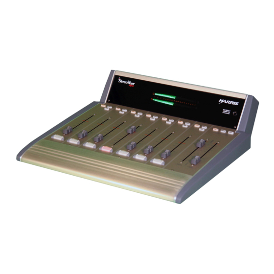
- Page 1 99-1395 Desktop Version 99-1396 Rack Version 71-1395 rev C 12/05 Broadcast Communications Division 4393 Digital Way • Mason, OH 45040 USA • Tel: 513.459.3400 FAX: 513.459.2890 • E-Mail: presupport@harris.com • Internet: http://www.broadcast.harris.com ® Designs by Pacific Research & Engineering – PR&E...
-
Page 2: General Information
Channels 5, 6 and 7 are stereo AES-3 digital inputs with employing Harris Corporation products designed by PR&E. Our integral sample rate conversion that accepts sample rates from mission is to provide the finest quality products, systems, docu- 32 to 48 kHz. -
Page 3: Power Supply
the output level of the built-in headphone amplifier. The room Power Supply monitor output is automatically muted whenever a Mic chan- A separate “line lump” switching power supply, with three nel is On (typically channel 1 is set as a mic, but channels 2 regulated output voltages, is supplied with both versions of and 3 can also be set as mics). -
Page 4: Mixer Operation
(pre-fader and pre-switch) to the talk output For those used to working on larger Harris or PR&E mix- and to the mix-minus output. This action also mutes the room ers and consoles, the SMX d ’s major difference is that each... -
Page 5: Program Outputs
The PGM 1 bus has priority, but PGM 2 is used when the BASIC MIXER OPERATION Telco is only assigned to PGM 2. The Mix-Minus with talk Follow these steps to initially operate the mixer: outputs always have talkback—even if the Telco channel is 1. -
Page 6: Installation
NOTE: A crimp tool is not supplied with SMX d . Use an set the switches to the +4 dBu position. For unbalanced de- AMP # 169481-1 crimp tool (Harris # 70-126) to crimp the vices, set them to the -10 dBv position and then connect the contacts. - Page 7 SMXD REAR PANEL CONNECTIONS ANALOG INPUTS LEVEL C/R WARNING DIGITAL INPUTS & DIPSWITCHES & TALKBACK LOGIC OUTPUTS ANALOG INPUTS ANALOG OUTPUTS START PULSE CHANNEL 1 POWER SUPPLY OUTPUTS & TIMER MIC LOGIC CONNECTION RESET OUTPUT When an unbalanced device must connect to a SMX d bal- balanced-to-balanced line transformer could alternately be anced analog output, and an IHF-PRO match box is not avail- used to interface an S/PDIF signal.
-
Page 8: Logic Connections
Talk audio to the room monitor and headphone outputs. Talk Tally Warning Tally J30 is used to plug in an optional Harris mic control panel Talk Tally Warning Tally for remote control of the Channel 1 functions On, Off, Cough... -
Page 9: Logic Interface
Pins 10 and 11 connect to a dry-contact input warning lamp ers, VistaMax outputs, recorders, etc.) to the remaining un- interface (like the Harris WL-2). If the warning interface re- used inputs (J1, J2 and J3 for analog devices; J13, J14 and quires high or low logic, and it is isolated, then J29 pin 12 (+5 J15 for digital devices). -
Page 10: Specifications
StereoMixer® digital carries a manufacturer’s warranty subject to the following guidelines and limitations: kind on the product. Except as expressly excluded herein, Harris Corporation (“Seller”) warrants equipment of its own manu- 15. A A A A A cc cc cc cc ccessor...


Need help?
Do you have a question about the stereomixer digital 99-1395 and is the answer not in the manual?
Questions and answers