
Related Manuals for Harris RMXDIGITAL


Summary of Contents for Harris RMXDIGITAL
-
Page 1: Technical Manual
Broadcast Console Operations & Technical Manual PRE75-53 PRE75-53 PRE75-53 PRE75-53 PRE75-53 Revision C.1 • 12/10 Broadcast Communications Division www.broadcast.harris.com... - Page 2 H A R R I S C O R P O R A T I O N Revision C • 10/07...
-
Page 3: Table Of Contents
Macro Files ..........A-8 VistaMax Integration ......3-9 Phantom Channels & Buses ..... A-10 Telco/Codec Operation ......3-10 INDEX 4 - RMXDIGITAL SERVER A - C ............. Index-1 RMXd File Structure ........4-1 C - L ............. Index-2 RMXd Server Configuration ......4-5 L - R ............. -
Page 4: Ce Declaration Of Conformity
513.459.3400 Equipment Description: Radio Mixing Console Equipment Class: Audio Equipment - Studio Model Numbers: RMXdigital Broadcast Console I the undersigned, hereby declare that the equipment specified above, conforms to the above Directive(s) and Standard(s). Harris Corporation–Mason Ohio USA Place Signature... -
Page 5: Safety Instructions
Safety Instructions 1. R R R R R ead A ead A ead All Instr ead A ll Instr ll Instr ll Instruc uc uc uc uctions tions tions tions..Read all safety and operating 16. P P P P P r r r r r o o o o o duc duct and C t and C t and C... -
Page 6: Manual Revisions
If you receive a revision to this document from Harris, replace the old manual pages with the new ones and discard the old pages. Replace this page with the new Manual Revisions page. -
Page 7: General Information
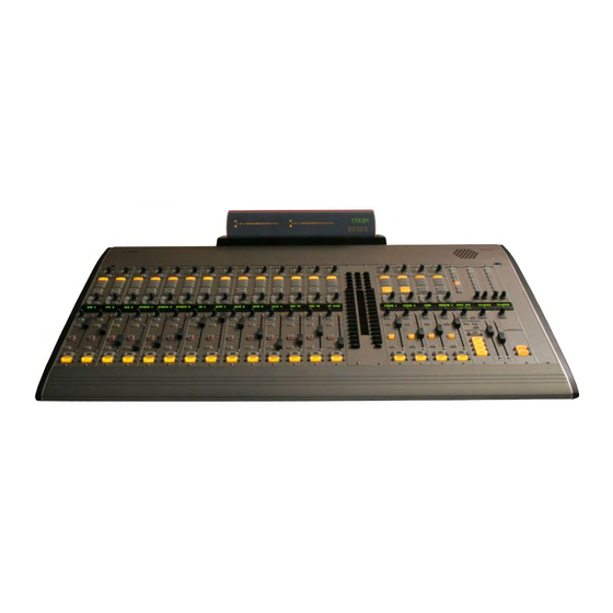
The RMX digital is a low profile, digitally-con- trolled, routable audio console that sits in a coun- broadcasters employing Harris Corporation prod- tertop cutout. Framesizes with 12, 20 or 28 con- trol strips are available. The console can operate ucts designed by PR&E. - Page 8 G e n e r a l I n f o r m a t i o n VISTAMAX CONTROL CENTER • Cue speaker and Cue monitor output * • Three talk audio outputs (Talk to: control room, The RMX digital is set up for daily use through studio, and an external location) * configuration files that are maintained by the sup- •...
- Page 9 G e n e r a l I n f o r m a t i o n Universal Dual Fader Panels For example, if the “morningzoo” session is cur- rently loaded on a RMX digital-12 console, and it Each Dual Fader panel has two sets of channel has configured the console inputs as: five mics strip controls with these functions: channel on/ (each with the talent’s name shown in the channel...
- Page 10 G e n e r a l I n f o r m a t i o n Monitor Control Panel When a source is selected using the source selector, This standard panel is divided into three the name is shown in the ten-character display functional sections: Session, Control Room, and and all source buttons are turned off.
- Page 11 G e n e r a l I n f o r m a t i o n This section of the Monitor Control panel also On the consoles, the KSU card plugs into the has two talkback buttons so the board operator motherboard behind the Monitor Control panel can talk to the studio and/or to an external and the two adjacent Dual Fader Input panels.
-
Page 12: Specifications
G e n e r a l I n f o r m a t i o n Specifications The RMX d 8-HL has a built-in 48-volt supply. All are supplied with a 110 VAC IEC input cord. Specifications are for the basic signal paths, per Two keyed 48-volt power cables are supplied channel, with 600 ohm loads connected to the ana- with the console mainframe Installation Kit so that... - Page 13 DC output: Keyed multi-pin connector 20 Hz to 20 kHz Dimensions Dynamic Range For all RMXdigital frames: height above countertop Analog Input to Analog Output: 104 dB referenced to is 2.25" [57]. Depth below countertop is 9.85" FSD, 107 dB “A” weighted to FSD [250] at the rear of the frame.
-
Page 14: Warranty
(USA) product warranty policy, dated July 1, 2007, is presented on the fol- lowing two pages. To view or download the current Harris Broad- cast Communications Standard Warranty Policy Statement for either domestic or international lo- cations, visit this Harris corporate website page: http://www.broadcast.harris.com/... -
Page 15: Technical Support
(or part thereof) from the geographical region of customer’s site, so as to minimize freight and duty. Harris bears the risk of loss or damage while the equipment (or part thereof) is in transit to customer from the Harris service center, and customer bears the risk of loss or damage while the equipment (or part thereof) is in transit back to the Harris service center. - Page 16 Licensed Programs shall operate substantially in compliance with Harris’ specifications for the Licensed Programs (the “Software Warranty”). The entire liability of Harris under this limited warranty is to provide, free of charge, a corrected copy of any portion of the Licensed Programs which is found by Harris inspection not to be in substantial compliance with its specifications.
- Page 17 1 2 3 4 5 6 7 8 9 0 1 2 3 4 5 6 7 8 9 0 1 2 3 4 5 6 7 8 9 0 1 2 1 2 3 4 5 6 7 RMXdigital-12 27.4" [696] 26.1"...
-
Page 18: Console Installation
TE: The number of available input slots equals the console available: 99-1411-1 is one input slot wide and holds one or model number (e.g., RMXd-20 has 20 input slots). All RMXdigital two single width turret panels; 99-1411-2 is two input slots wide... -
Page 19: Channel Configuration
2 Installation CHANNEL CONFIGURATION Setting Dual Fader Panel Rotary Switches Each Dual Fader panel’s specific operations and Determine which channels will be designated functions are established through the settings in as Telco channels (up to six can be assigned) and the init.mac file and the current session file. - Page 20 2 Installation Program 1 Meter Auxiliary Meter Remove the Dual Fader panels that need to have their rotary switches changed (from the default 0 settings) from the mainframe (see page 5-3 for panel removal instructions). The console power can be left on while unplugging and reconnecting the Dual Fader panels.
- Page 21 2 Installation the right-hand meter, which switches to display an ESE or SMPTE master clock, the clock runs the cue bus level while Cue is active. off its internal oscillator. Both display colons flash The meter display mode (average only or aver- to indicate ESE timecode is not detected.
- Page 22 2 Installation Clock Option Switches (DS1) Clock Settings SWITCH 1 2 3 4 5 6 7 8 9 0 1 2 3 4 5 6 7 8 9 0 1 2 1 2 3 4 5 6 7 8 9 0 1 2 3 4 5 6 7 8 9 0 1 2 The operating mode (autonomous, ESE slave SWITCH UP DOWN...
- Page 23 3 - Blue LED turn on level* 3 - unused 4 - Blue LED turn on level* 4 - 12-hour time / 24-hour time 5 - NetWave / RMXdigital 5 - SMPTE not used / SMPTE master clock 6 - Display: mirrored /direct view J4 SIGNALS...
- Page 24 It plugs into the Redundant Connect the broadcast facility’s technical ground power connector using a second power cable, sup- to the RMXdigital mainframe, using the threaded plied with the console mainframe. insert provided on the rear of the chassis near the power connectors.
- Page 25 2 Installation BACKUP BATTERIES Three AA rechargeable NiCad batteries (part of the Tool Kit) supply a “Keep Alive” voltage to main- tain the console assignments during momentary power outages. Do NOT install the batteries until the console is powered 24/7 and is ready for everyday use.
-
Page 26: Cabling And Wiring
2 Installation Cabling and Wiring needed is determined by the application. Typically, cables with five or eight wires are Before installing the RMX digital console, cre- most often used for constructing logic cables ate a facility wiring plan to list the console inter- since even though there are twelve or four- connections with all peripheral devices. - Page 27 2 Installation Insulation Crimping Barrel 9/64” [3.57 mm] AMP MOD IV Contact Crimp Tool Wire Crimping Barrel Properly Crimped Contact Insert the prepped wire into the contact until the insulation hits the tool’s wire stop. Hold the wire in place while squeezing the tool handles to crimp the contact onto the wire.
-
Page 28: Audio Connections
2 Installation A receptacle contact is inserted into the hous- Normal these signals to the appropriate analog ing with its locking tab side toward the locking inputs. Likewise, the RMX digital ’s analog outputs may tab slots on the side of the connector housing. A slight click can be heard when the contact’s lock- be routed through a patch bay normalled to stan- ing tab springs up into the locking tab slot. - Page 29 S/PDIF product. When an unbalanced device must be connected to an RMX digital balanced analog output, and RMXDIGITAL SAMPLE RATE an IHF-PRO match box is not available, do not The RMX digital uses the professional audio tie the low (-) and shield pins together to “unbal-...
- Page 30 2 Installation LOGIC CONNECTORS (the RMX digital is then automatically synchro- nized to the VistaMax system’s master clock). The RMX digital console has the following logic An external AES-3 digital reference signal connections: (48 kHz, ±100 ppm) can connect to the master •...
- Page 31 2 Installation Control Room Logic Interface, 4 Control Room Warning Relay Connector Pinout and Block Diagram Control Room Warning Relay Control Room Dim Relay Enable Logic Inputs (+) 1 2 3 4 5 6 7 Control Room Mute Relay 8 9 10 11 12 13 14 Wire insertion end view Ctrl Room Mute Input (-) 1 - LOGIC GND...
-
Page 32: Frame & Console Display
Logic inputs, noted by the (-) symbol, relay contacts (pins 4 and 5) for controlling a warn- are active low. They are isolated by opto-couplers ing lamp interface like the Harris WL-2. It is acti- 2-16 H A R R I S C O R P O R A T I O N Revision C •... - Page 33 2 Installation vated when any channel with a studio mic as its channel strip while tally outputs control the but- source is turned On. ton tallies in sync with the channel strip buttons. The other three logic outputs (commoned to- The init.mac or the active session file sets the gether on pin 10) are for studio dim (pin 12), stu- binding for the Assignable connector logic (to as-...
- Page 34 (additional pulses with each button press), or they can be set for sustained logic. In the basic logic connection example on page Mic Logic To/From a RMXdigital Two mic control panels are available for the 2-26, active low logic is used, thus Tally & Pulse...
- Page 35 2 Installation channel, then controls the off LED illumination, The frame has two connectors for the Console when Ready control is active for that channel. Display’s umbilical cable. These carry the timer Otherwise, the off LEDs turn on automatically at control wires, the digital bargraph meter signals channel off.
- Page 36 (not included) KSU CARD VISTAMAX AUDIO MANAGEMENT SYSTEM FRAME (not included) ESE or SMPTE MASTER CLOCK (not included) RMXDIGITAL FRAME, REAR PANEL, PARTIAL VIEW 48 VDC CONNECTORS 1 & 4: +48 VDC 2: SHIELD 3 & 6: 48 RETURN ESE/SMPTE...
- Page 37 O L ROOM & STUDIO — OOM & STUDIO — OOM & STUDIO — Two 14-pin monitor RMXdigital activity. connectors for separate control of control room and studio logic. See page 2-20 for signal details. F F F F F A A A A A CET 0,...
- Page 38 WARNING RELAY (pins 4, 5) Isolated N.O. dry contacts for control of a warning lamp interface (like the Harris WL-2) when a mute command is received. Up to 60 volts at 350 mA can be switched through the contacts.
- Page 39 2 Installation KSU CARD CONNECTIONS (CONT.) Assignable Logic I/O Default Signal Definitions (also applies to the 8-Input Expansion Card Logic I/O) (see page 2-13 for a simplified circuit block diagram) PIN NAME / NUMBER FUNCTIONAL DESCRIPTION START PULSE Equivalent to a Normally Open (N.O.) relay contact (the common contact is pin 6). The output logic type is (pin 11, Line logic) set in the session file for: one momentary 220 msec contact closure when the channel is turned On from Off;...
- Page 40 2 Installation KSU CARD CONNECTIONS (CONT.) Cue/Talk/External Logic I/O Signal Definitions (see page 2-13 for a simplified circuit block diagram) PIN NAME / NUMBER FUNCTIONAL DESCRIPTION RELAYS COMMON (pin 3) The Common (C) relay contact output for the Talk, Dim, Mute, and Timer Reset relays. It can be set for active low or high logic: for an active low output jumper this pin to logic ground;...
- Page 41 2 Installation QUICK GUIDE TO THE 8-INPUT EXPANSION CARD CONNECTIONS The optional 8-Input Expansion card adds eight audio inputs and eight Assignable Logic I/O connections to a DSP Card. There can be one 8-Input Expansion card added to each DSP card in a console. Since the RMX d -4 does not have a DSP card, an 8-Input Expansion card cannot be used in that size frame.
- Page 42 PRE99-1363-1 PRE99-1362 PRE99-1363-2 PRE99-1361 PRE99-1361 PRE99-1365 PRE99-1363-1 PRE99-1362 CAT-5, straight-thru type From additional: RMXDigital KSU cards; BMXDigital Session Modules; CAT-5e or CAT-6 setup computers; Crossover type cables VistaMax frames; VistaMax control panels NETWORK SWITCH KSU CARD 2-26 H A R R I S C O R P O R A T I O N Revision C •...
- Page 43 2 Installation MIC REMOTE CONTROL CONNECTION EXAMPLE This example shows a mic remote control panel connected to an Assignable Logic I/O connector, using the default logic settings. Information on binding the logic to the mic audio input and the channel strip session settings for microphones are covered in chapter 4, RMX digital Server and in Appendix A, VMCC.
- Page 44 2 Installation BASIC PERIPHERAL DEVICE LOGIC CONNECTION EXAMPLE This example shows a peripheral device (with basic logic functions like the CD player shown below) connected to an Assignable Logic I/O connector using the default logic settings. Information on binding the logic with the peripheral’s audio inputs and the channel strip session file settings for peripherals are covered in chapter 4, RMX digital Server and in Appendix A, VMCC.
- Page 45 2 Installation COMPLEX LOGIC CONNECTION EXAMPLE This example shows a peripheral device with complex logic functions (a digital delivery system) connected to an Assignable Logic I/O connector, using default logic settings. For most peripheral devices, the logic ground and +5 volt supply connections are not used, but in this example all of the digital delivery system connections are also isolated.
-
Page 46: Buttoncap Lenses
CD- and print the page. ROM or on the Harris FTP site (see page 5-1 for If the printed test sheet does not line up with access info). It is used with the 80-1961 clear in- the blank 80-1961 sheet, then try printing using sert sheet to create custom lens labels. -
Page 47: Console Operation
Console Operation MONITOR CONTROL PANEL his chapter covers how to use the RMX- This standard panel is installed near the right side of the frame. The panel is divided into three digital console controls. columns: • Session / Timer / Aux Meter controls Console Overview •... - Page 48 Operation UNIVERSAL DUAL FADER PANEL QUICK GUIDE Each panel has two identical “channel strips” for independent control of two audio sources. The initial audio source for each channel strip is set by taking a session file. Sources may then be manually changed on the panel using the Source Selector and Take button, or by taking a different session file.
- Page 49 Operation UNIVERSAL DUAL FADER PANEL (CONT.) SEND This section has the send bus controls. ON/OFF — ON/OFF — ON/OFF — ON/OFF — ON/OFF — When lit, routes the input audio to the send bus through the send volume control and the Pre Fader and Pre Switch controls. When unlit, no audio on this channel goes to the send bus.
- Page 50 Operation MONITOR CONTROL PANEL QUICK GUIDE This card is divided into three columns by function: the left column has the auxillary meter source selectors, the session file controls and timer control buttons; the center column has the control room monitoring controls (monitor source selectors and level controls for the control room speakers and operator headphones);...
- Page 51 Operation MONITOR CONTROL PANEL QUICK GUIDE, LEFT COLUMN CONTROLS AUX METER The buttons in this section have removable lenses for custom labels. The signal assigned to each button is set during console configuration. As shipped from the factory, the assigned signals are: EXT —...
- Page 52 Operation MONITOR CONTROL PANEL QUICK GUIDE, CENTER COLUMN CONTROLS CONTROL ROOM All CR outputs use the same monitor source. The selected source is usually indicated by a lit button but, if Auto Mic Switching is enabled (to switch between the Real Air source (typically EXT) and a Synthetic Air source while a CR mic channel is On), then the Real Air button (typically EXT) flashes to indicate Synthetic Air is the monitor source.
- Page 53 Operation MONITOR CONTROL PANEL QUICK GUIDE, RIGHT COLUMN CONTROLS STUDIO All Studio outputs use the same monitor source. The selected source is usually indicated by a lit button but, if Auto Mic Switching is enabled (to switch between the Real Air source (typically EXT) and a Synthetic Air source while a Studio mic is active), then the Real Air button (typically EXT) flashes to indicate the Synthetic Air is the source.
- Page 54 Main Meter Auxiliary Meter Time-of-Day Clock Event Timer RMXdigital’s Low-Profile Reflective Display CLOCK A detailed bargraph meter is shown below. Each The clock displays time in hours: minutes: sec- bar segment, from 0 to -30, represents a 1 dB level onds in either 12- or 24-hour time.
-
Page 55: Rmx Digital Applications
Operation nal level) or average and peak (a solid bargraph fic feed, a processed mic, a digital delivery system represents the average level with a single bar, typi- output, an ISDN output—any audio signal needed in the facility that is plugged into a RMX digital cally 6 to 10 dB higher than the average bargraph, representing the peak level). -
Page 56: Telco/Codec Operation
AUTO F/B button, which audio management system, see the VistaMax when lit uses the Telco channel’s state (channel manual (Harris # 75-52). On or Off) to automatically select which bus is used as the foldback source. - Page 57 Operation signed, then the source is selected in bus order; ing a live remote PGM 2, PGM 3, PGM 4, then Offline. where a “broad- While the Channel is Off: The Offline bus is the cast” feed to the Foldback foldback mix bus.
- Page 58 Operation Note: Offline feeds from non-Telco channels are lower priority buses are assigned on more To Record Telco channels. always pre-switch. They were set to Pre- or Post- As in creating the foldback mix, the bus prior- Fader during console setup. The Telco channels’ ity order changes when any To Record Telco has Offline bus feeds can be separately set for Pre- or AUTO F/B On.
-
Page 59: Rmxdigital Server
The RMX digital Server stores these file types: • Sessions (.ses suffix) • Macros (.mac suffix) Files and Folders on the RMXdigital Server • Console setup (.ini suffix) • Console configuration (.cfg suffix) An FTP program is used to access the console’s The RMXd igital Server also functions as an FTP flash disk. - Page 60 SesFiles number and build date. This can be compared to folder. the current operating system build on the Harris A session file is loaded into the console by first FTP site (see page 5-1 for access details). The using the Monitor Control panel’s rotary Session...
- Page 61 ID for that particular SBC. This number can be sets whether a VistaMax or another type of router given to a Harris tech support representative in is networked with the console. [SrcInclude] order to receive a License Code (entered into...
- Page 62 4 RMX digital Server the KSU B analog output). The right hand but- EDGEDEVICE.INI This file, maintained using VMCC, configures tons are conversely set as six destination selectors edge devices (console or rack-mount source or (Button_2_1 thru 6) for signals 245 - 255: the source/destination selector panels) that receive KSU C and D analog outputs and the four KSU their information from the RMX digital Server.
-
Page 63: Rmxd Server Configuration
99-5000 CD-ROM. They can also be down- that its displayed name is KSU A ALG; and that loaded from the Harris FTP site (see page 5-1 in the signal is stereo linked to the next signal (by Maintenance for FTP access details). - Page 64 RMX d Server: back to the console or frame. The program is also Direct Connection useful for downloading files from the Harris FTP site. 1 Connect a crossover CAT-5 cable between the KSU card’s Ethernet connector and the 3CDAEMON Ethernet port assigned to IP 192.168.100.11...
- Page 65 (File, Edit, Tools) Hide Summary Pane button Community Name To Reorder Summary List, Community Devices click #, Address, or Name R = RMXdigital B=BMXdigital E= Edge device Active Device (parameters shown in the editing pane) Left Pane Activity Selection Tabs...
- Page 66 4 RMX digital Server 100.11). The other settings can be left at their box to add the check mark). Click the Inspect default settings at this time. button to inspect the console’s information. The The Editing pane is also where configuration information line shows “done”...
- Page 67 (doubleclick on the Enable boxes to add a check mark). Provisioned File List for RMXdigital Clicking on a file name displays the file con- tents in the provision editor pane. Even though files can be manually edited in the provision...
- Page 68 4 RMX digital Server CONFIGURATION NOTES AND TIPS work. Always confirm all IP addressing choices with a knowledgable network administrator. If a console is not networked with a VistaMax Before the setup computer can access the RMX d system, it could continue to use the factory de- Server, its IP address must be changed so it is in- fault IP address (192.168.100.22).
- Page 69 To obtain a License, the Server ID number for Include Lists. the console (listed in the serverid.txt file) must be given to a Harris Technical Services or Sales Representative so that they can generate a License Code for that specific RMX digital console.
- Page 70 4 RMX digital Server the Signal Summary + button and then highlight or Description and edit them as required. If too either Sources or Destinations. This pane is where many characters are entered or if an illegal char- signal names are assigned, mono/stereo selection acter is entered, a red exclamation point and is set and setting whether a signal is hidden or error warning box will be shown so the error...
- Page 71 4 RMX digital Server A Hidden signal has a check mark in the with a Ready command output to indicate sta- Hidden column. This means it is not available tus of the device. The Off lamp on the channel to be added to any signal include list. For most strip that this signal is routed to will then be installations, the default settings for Hidden will controlled by the incoming Ready logic com-...
- Page 72 4 RMX digital Server crophones. The appropriate Room Code is then Select Monitor/Meter Include Lists & Sources set on each mic input. When the mic is routed There are three columns of seven buttons on to a channel strip, its room code is compared the monitor module to select the Aux Meter with the assigned room codes on the console so source, the Control Room monitor source and...
- Page 73 These two signal selections—just below the Room Code Assignments Real Air source selection box, assign two con- Note: the Studio 2 entry is not used in RMXdigital. sole or system inputs as the sources for an Ex- The room code entry boxes are just below ternal Cue input and an External Talk to Con- the Destination Include List entry.
- Page 74 4 RMX digital Server tions, a session file on another device will also checked, the offline bus is pre-fader. When Cue need to be loaded, so it is also entered here. Cancels With On is In the example, mix-minus.ses is a setup checked, turning any file on device 3.
-
Page 75: Session Files
4 RMX digital Server Session Files Use a text-only editor (Windows® Notepad) to add or update any session settings (e.g., changing the Session files are text files with the suffix .ses. default channel source, adding button lockout in- Pressing Save on the Monitor Control panel saves formation, etc.). - Page 76 4 RMX digital Server Rotate the Session selector clockwise (CW) to The newly created template session move up through the list. Rotate it counterclock- (undefine01.ses) now contains the standard wise (CCW) to move down through the list. When console surface settings. To add lockout informa- the desired session is shown in the bottom line of tion, or to rename this file, it must be downloaded from the RMXd igital Server to a setup computer...
- Page 77 4 RMX digital Server 3 Open the Storage Card folder, then the Data play as the Monitor Control panel’s Session Se- folder, then the SesFiles folder. The folder’s con- lector is rotated. tents were shown on page 4-1. Note: Session names can have up to ten al- Note: Create a shortcut to go directly to the phanumeric characters, but cannot use spe- SesFiles folder in FTP Voyager by clicking Tools ,...
- Page 78 2, which in this case is the numbered from the left end of the frame (number RMXdigital console. 337-352 are the analog and 01) to the right. The maximum number of Univer- digital inputs on the KSU card.
- Page 79 99-5000 CD-ROM and they are also available to be manually edited as they do not have control from the Harris FTP site (see page 5-1 for ac- surface buttons. These include the sections [ON], cess) in the customer_support/rmxdigital folder.
- Page 80 4 RMX digital Server • [TelcoAuto] Sets whether the Auto while channel 2 is immediately turned Off—even Foldback feature is on or off for each Telco if the channel is on-air. channel. Typically, there are no entries under the [On] •...
- Page 81 4 RMX digital Server outs are typically set for unattended console op- The table entries are in hex, with Map_0 being eration or when a special console setup must be a reserved position listed as 00 for no channel de- maintained.
- Page 82 4 RMX digital Server Include Lists and destinations. The section header [Router Command_1], is used in the init.mac file to set A source can only be routed or selected on a up the default routing for the audio and assign- channel strip source selector if it’s a source listed able logic connections on the KSU and 8-Input on the console’s Source Include List, which is...
- Page 83 4 RMX digital Server [Router_83] • [room_code_mute] Assigns a room code Take=0 for the three console destinations: control [Router_84] Take=0 room, studio 1 and external. There is also a definition for Studio 2, but that is not used The Take= line sets the source for the channel by RMX digital .
-
Page 84: Session & Macro Files
4 RMX digital Server to 15 sources), and defines the sources for in order. This gets automatically assigned the seven monitor select buttons. by the VMCC as the ports are defined. • [port_config_card_x] This section [monitor_selection] Include_1=D9.337-351,173,175 defines logic outputs (those not defined in definekey_1=10 definekey_2=5 the [on_out_port_card_x] section) for... -
Page 85: Software Updates
Software Updates To update the RMX digital software: 1 Configure the TFTP Server to point to the folder Harris Corporation may periodically issue soft- on the CD-ROM that contains the updated sys- ware revisions for the RMX digital Server at no tem software following the instructions in the charge. - Page 86 4 Run FTP Voyager on the setup computer and HyperTerminal Port Settings for communicating with the RMXdigital Server enter the username and password as required to view the Storage Card folder contents. 4-28...
-
Page 87: Parts And Repair Services
Parts and Repair Services To order assemblies or to request an RA con- tact Harris by mail, phone, fax, e-mail, or visit the There are only a few parts that are field replace- Harris Website: able on the RMX digital (see page 5-2 for part num-... -
Page 88: Spare And Replacement Parts
99-2672-2 KSU Card (with optical connectors) 95-2672-2 KSU, main PCA 76-1400 Installation Kit 95-2675 KSU, analog connector PCA Harris # Description or Use Qty. 95-2677 KSU, digital connector PCA 14-482 3-pin AMP MOD IV housing 99-1800 Single-board computer PCA... -
Page 89: Console Troubleshooting
5 Service Console Troubleshooting Which control is being shown is identified by the yellow and red LEDs under each source display. There are diagnostic test modes built into each The operation of each button is tested in this mode Universal Dual Fader panel and the Monitor Con- by pressing the button. -
Page 91: Control Panel Servicing
4 Remove the snap-on fader cover (held in place NOTE: If you need to replace one of the assem- by plastic end tabs). blies, please contact Harris Technical Services 5 Clean the fader using a dry cotton swab or Department for service or replacement parts. -
Page 92: Console Display Service
5 Service CLOCK TROUBLESHOOTING NOTE: The use of chemical cleaners on the con- ductive plastic will substantially shorten fader life. If the clock’s colons are blinking, it indicates Never touch the fader slider contact fingers while the clock is set for slave mode, but the ESE or cleaning the fader parts. -
Page 93: Backup Batteries
5 Service Any channel that should reset the timer when 48 Volt Power Supply turned on needs to be set as =1. Those channels set as =0 do not reset the timer when turned on. Periodically check that vent openings are not For more information about session file settings, blocked and there is no dust buildup on the top see Chapter 4 RMX digital Server. -
Page 94: Frame Component Info
Each red CAT-5 is routed through a round ac- panel or a Divider Kit (used to add Harris turret cess hole up to the control panel section of the control panels into the frame). -
Page 95: Ksu Card Service Info
5 Service tion, the KSU is the network interface for the Vis- can be made or sessions taken or saved. taMax system for both communications and for Pressing the other reset switch (System) causes the VistaMax Link I/O. audio signal interruption by resetting the console. It is equivalent to power cycling the console by turning off the power supply. -
Page 96: Motherboard Service Info
RMX digital . They plug directly into one another for their frame orientations. and fasten to the bottom of the card cage. Which card types are installed depend upon frame size, as shown in the Motherboard Orientation illus- RMXDIGITAL MOTHERBOARDS RMXD-20 Motherboard Configuration From Console Studio... -
Page 97: Accessories
Furniture and Cabinetry Harris offers a full line of standard and custom furniture and cabinetry specifically designed to house the RMX digital console with studio periph- eral equipment. Complete turnkey studio design and implementation services are also available. - Page 98 6-1). The 99-1198 (shown in the Host Selector Panel (99-1190) with the RMX digital . The Turret example above) adds a Talkback button to panel connects to the rear of the RMXdigital using the three basic panel buttons. A simplified sche- a straight-thru CAT-5 cable.
-
Page 99: Host Turret
Headphone level is digitally controlled when the peripheral devices. 99-1214-series headphone panels are used. Head- To assist in installation, Harris also offers pre- phone panels are available with and without a made peripheral logic cables for many popular volume control pot. Those without a pot are de- devices. -
Page 100: Application Examples
* Resistor Pack R1 limits the LED current. Its value is determined by the voltage supplied by the console. Panels ship from the GNDD factory with the 5 Volt resistor pack installed. Console Resistor Mic Remote Pack Value Harris P/N Digikey P/N Logic GNDD 5 Volts 47 ohms 6-786... -
Page 101: Appendix A: Vmcc, Sessions
RMX digital console. A VMCC errata section COMMUNITY MONITOR (CM) covers program use notes and applications. The revision D release of the Harris # 99-5000 CM (tray icon: ) is not only a valuable tool CD-ROM first introduced two major changes to for setting up a VistaMax system, it’s also helpful... - Page 102 IP address so it falls within Client is accessed from the Start menu (under Pro- the missing device’s subnet, as listed in the CM grams/Harris Corp/VistaMax on the admin com- status display. Once that is done, use FTP Voy- puter).
-
Page 103: Vmcc Operations Errata
The latest release build is 2 - Entry set in the Device edit pane 3 - Entry set in the Community edit pane available for downloading from the Harris con- Tier Naming Convention Summary sole FTP site (see page 5-1 for access details). - Page 104 Appendix A VMCC Call Sign groups then receive the System Publish and VistaMax cardframes since these signals are shared throughout the community. If the conven- file, whose names consist of: the Call Sign, the first tion is used on consoles, however, each common character of the Discipline Prefix name and the console signal name (PGM 1, PGM 2, and so on) Community Name (e.g., XYZP .MD1).
- Page 105 Appendix A VMCC to the buttons, those two signals must first be Talk to Studio 1 Co-Host, Talk to Studio 2, Talk added to the various include lists. This is covered to Studio 2 Host and Talk to Studio 2 Co-Host. in the next section on Telco settings.
- Page 106 Appendix A VMCC device or changing the parent on an existing edge If the two devices do not match exactly, VMCC device does not automatically update the edge de- only allows the inspected device to be added as a vice location in the Explorer pane. new community member.
- Page 107 Appendix A VMCC sole is not affected. However, all of the static sec- uses a separate line within the section with a cor- tions that were loaded when the previous session responding Entry Value (there is a 1,000 charac- or macro file was taken are erased, which includes ter limit, which may be further limited by con- the following session file sections: straints imposed by a particular section);...
- Page 108 Appendix A VMCC which is the device number followed by a period sole with Telco channels assigned. They must then and the local signal number. Each of the example be manually edited since RMX digital has no con- numbers reference the Mix-Minus 1 signal on the trol surface buttons to set their conditions.
-
Page 109: Macro Files
Appendix A VMCC [RouterCommand_1] The previous macro is selected on fader 12. If this This section can specify up to sixty-three routes Telco hybrid will also be available on fader 13, to be taken when the session or macro file is taken. then this macro would be included on fader 13: Typical usage was shown in the examples under [RouterCommand_1]... - Page 110 Appendix A VMCC Filename is the macro’s file name minus the a .ses suffix, they do not show up in the Session selector. If a board operator needs to load a macro, .mac file extension. under 500-series code, the macro can be included ,d is an optional entry to specify a device num- as a “source”...
-
Page 111: Phantom Channels & Buses
Appendix A VMCC When the operator dials through the available them—including the phantom channels, from a sources, the macro names (remote, telco_norm, session or macro file. To use these phantom buses, request) appear in the list alphanumerically edit the session file by changing the channel entry along with the other signal sources included. - Page 112 Appendix A VMCC session file is taken. If the signal level must be set could affect on-air audio if used improperly and to a level other than unity gain, then do not use thus should only be used in a special session file. pre-fader, but instead enter a fader level setting To avoid this situation, when using phantom for the channel by adding a [fix_fader] sec-...
- Page 113 Appendix A VMCC 500-SERIES CODE FEATURES right arrow) so the names appear in the Call Group The 500-series code has added several new fea- Members list at the right side. tures, including the ability to include macro names Once the call groups are formed, they are added with signal sources names on both edge devices to the include list for the intercom parent device: and fader channel source selectors, as previously...
- Page 114 Appendix A VMCC In 400-series code, return logic routes were in the past since macro files do not have to cre- manually created by using a macro file to route ated to handle the return logic routing. the signal with logic to a channel and to then route There are still some signals where using return the logic from the fader channel back to the pe- logic routing may not be desirable.
-
Page 115: Index
Component Descriptions ......1-3 Analog Connections ......2-12 Connection Examples Digital Connections ......2-12 Basic Logic Example ......2-28 RMXdigital Sample Rate ....2-13 Complex Logic Example ....2-29 S/PDIF Connections ......2-13 Mic Remote Control Example ..... 2-27 Unbalanced Connections ....2-13... - Page 116 Grounding and Shielding ......2-8 Overview ..........2-17 Guest Panels (Mic Remote Panels) ..... 6-2 Signal Definitions ....... 2-24 Harris Contact Information ......5-1 Declaration of Conformity ......iv Hazard Label Identification ......v Denon CD Player Connection Example ..2-28 Headphone Distribution Amp ....
- Page 117 Index Page numbers listed as chapter-page. CONT Logic (continued) Parts Cable, Mic Remote Panel ...... 6-4 Ordering ..........5-1 Connectors ........2-14 Part Lists ..........5-2 Control Room Logic ......2-16 Peripheral Devices Cue/Talk/External Logic ....2-17 Basic Peripheral Example ....2-28 Interface ..........
- Page 118 Index Page numbers listed as chapter-page. CONT Safety Instructions ......... v Studio Logic I/O Sample Rate ..........2-13 Overview ........... 2-16 Server (see RMX digital Server) Signal Definitions ......2-22 serverid.txt File .......... 4-3 Studio Monitor Selector panel ....6-2 Service ............
Need help?
Do you have a question about the RMXDIGITAL and is the answer not in the manual?
Questions and answers