Table of Contents
Advertisement
O W N E R ' S M A N U A L
1. Read this manual carefully before starting assembly. Read each step completely before beginning
each step.
2. Some smaller parts may be shipped inside larger parts. Check inside all parts and cartons
before assembling or ordering parts.
3. To make assembly of your basketball system easier , use the Hardware Identifier on page 4
to identify and sort all fasteners. Check all cartons for kits. All hardware may not be
located in one kit.
4. Do not tighten hardware until instructed to do so. If hardware is tightened too soon, mounting holes
may not align and parts may not easily fit together . Leave locknuts slightly loose until you are instructed to
tighten them.
5. An electric screwdriver is helpful in assembly. However, please set at low torque and use caution
because you could overtighten the hardware and strip the screws.
6. Save these instructions and your proof of purchase (receipt) in the event that the manufacturer
has to be contacted for replacement parts.
Please Do Not Return This Product T o The Store!
Contact Escalade
Phone:
1-888-USA-GOAL
Fax:
1-866-873-3536
E-mail:
basketball@escaladesports.com
Mailing Address (correspondence only):
Escalade Sports
PO Box 889
Evansville, IN 47706
Please visit our World Wide Web site at:
ON-LINE TROUBLE SHOOTING
ON-LINE PARTS REQUESTS
ADDITIONAL ESCALADE
Escalade
Sports products may be manufactured and/or licensed under the following patents:
®
6419596, 6179733, 5919102, 5071120, 4798381, 4424968, D326128, 7244046
Additional patents may be pending. One or more of the listed patents and/or pending patents may cover specific product.
Sports customer service department at:
®
SPORTS PRODUCT INFORMATION
®
T
oll Free!
T
oll Free!
www.escaladesports.com
TECHNICAL ASSISTANCE
FREQUENTLY ASKED QUESTIONS
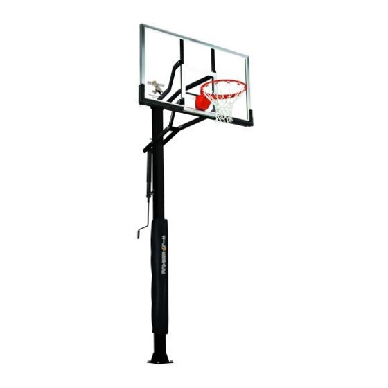
MODEL NO.
B5402
SB60
BASKETBALL SYSTEM
2L-7538-01
©
2013 Escalade Sports
®
Advertisement
Table of Contents

Subscribe to Our Youtube Channel
Related Manuals for SilverBack B5402


Summary of Contents for SilverBack B5402
- Page 1 MODEL NO. B5402 SB60 BASKETBALL SYSTEM O W N E R ' S M A N U A L 1. Read this manual carefully before starting assembly. Read each step completely before beginning each step. 2. Some smaller parts may be shipped inside larger parts. Check inside all parts and cartons before assembling or ordering parts.
-
Page 2: Safety Instructions
SAFETY INSTRUCTIONS FAILURE TO FOLLOW THESE WARNINGS MAY RESULT IN SERIOUS INJURY AND/OR PROPERTY DAMAGE. Owner must ensure that all players know and follow these rules for safe operation of the system. Owner must ensure that all players know and follow these rules for safe operation of the system. WARNING FAILURE TO FOLLOW THESE WARNINGS MAY RESULT IN SERIOUS INJURY AND/OR PROPERTY... - Page 3 WARNING DO NOT DUNK ON THIS UNIT . DO NOT HANG FROM ANY PART OF THIS UNIT , INCLUDING THE BACKBOARD, RIM, SUPPORT BRACES OR NET. 4L-8152-01 (Affixed to Top Post on the front side) Bottom of upper pole must cover the above orange portion of this sticker (6”...
- Page 4 3/8”-16 Nylon Insert Lock Nut (14 Pieces) 3/8-16 X 71/2” Hex Bolt (1 Piece) 1/2”-13 Nylon Insert Lock Nut (1 Piece) #10 X 1 1/8” (10 Pieces) 3/8-16 X 7” Hex Bolt (3 Pieces)
- Page 5 Vertical main post assembly is a two part process. PART 1 PART 2 ® Day 1. Complete Anchor System Installation Instructions. Day 5. Complete Silverback assembly instructions. (Requires (Below) four adults) Day 2-4. Allow concrete to cure. ANCHOR SYSTEM INSTALLATION INSTRUCTIONS (Day 1) Figure 1 16”...
- Page 6 ASSEMBLY INSTRUCTIONS (Day 5) ASSEMBLY INSTRUCTIONS (Day 5) TOOLS REQUIRED FOR THE FOLLOWING STEPS TOOLS REQUIRED FOR THE FOLLOWING STEPS 1 - 15/16" Open end Wrench 1 - 15/16" Open end Wrench 1 - Phillips Screwdriver 1 - Phillips Screwdriver Be sure that the Be sure that the 1 - 15/16”...
- Page 7 NOTE: Self Drilling screws (#77) are used. Holes are SCREWS (#77) MUST BE INSTALLED TO POLE AS DESCRIBED only on outside Pole. User IN STEP 3. FAILURE TO INSTALL SCREWS COULD RESULT IN must insert screws through SERIOUS INJURY OR PROPERTY DAMAGE. BOTH POLES.
- Page 8 If not already pre-assembled, slide Plastic Actuator Sleeve (#15) over Steel Actuator (#16) and place Actuator Cap (#13) on top. Align holes in all 3 parts and slide P ivot Tube (#14) through holes in Actuator Cap (#13), Plastic Actuator Sleeve (#15) and Steel Actuator T ube (#16) until equal amounts stick out through both sides of actuator .
- Page 9 Attach lower arms (#11) to Top Pole (#3), as shown in IMPORTANT! Nylon washers (#5) adequately space painted parts at all pivot points. Neglecting the use of Figure 7, using a hex bolt (#22), two flat washers (#18), these washers will result in rusted parts. two plastic washers (#5) and lock nut (#4).
- Page 10 Attach long leg of Upper Arms (#6) to Top Pole (#3), as shown in Figure 9, using a bolt (#7), two flat washers (#18), two spacers (#8) and one lock nut (#4). Note: Tighten bolts snug but, do not over tighten. Board Arms must pivot freely Figure 9 Figure 7...
- Page 11 Slide Actuator Crank (#42) onto shaft on the bottom of Actuator (#16). Line up hole in shaft with hole in Actuator Crank and insert Pin (#41) to secure. See Figure 11. To aid in the assembly of the backboard, lower the backboard, by turning the Actuator Handle, until the lower arm makes contact with Stop Spacer (#10).
- Page 12 Figure 13 Note: Make sure (#27) Rim Pad is installed between Rim (#28) and Backboard (#23) Mount Goal Assembly (#28) and Rim Pad (#27) to Backboard, as shown in Figure 13, using four bolts (#49), four washers (#26), and four locknuts (#4). Tighten fasteners, but leave them loose enough to level rim.
- Page 13 Raise Backboard to 10 FT. regulation playing height. Measure from top of rim straight down to the playing surface. Using tape - mark the side of the steel actuator (#16) just under the plastic actuator sleeve (#15) at this 10 ft rim height.
- Page 14 Two adults are recommended for this step, one to level and one to adjust the bottom #35 nuts. If further leveling is required loosen top #35 nuts but do not loosen past the top of #39 “J” Bolt. DO NOT REMOVE NUTS #35 Place a level on pole and adjust bottom nuts #35 with a 15/16”...
- Page 15 Any labor costs, travel expenses and any other changes involved in the ® removal, installation or replacement of the defective/repaired parts from/to your Silverback System will be the purchaser’s responsibility.
- Page 16 To ensure ease of operation, lubricate all pivot points at least every 6 months or as needed with a good lubricant such as WD-40. – RUST – , remove loose paint, sand lightly, primer and paint with exterior flat matte finish Inspect your pole periodically, if rust should appear enamel paint. B5402 REPLACEMENT PARTS LIST Key# Part # Description Qty. Key# Part # Description Qty.
- Page 17 (Pre-Installed) (Pre-Installed) Note: All #9 Caps (Pre-Installed) are Pre-Installed. , IN O RT (Pre-Installed) 2L-7538-01...
Need help?
Do you have a question about the B5402 and is the answer not in the manual?
Questions and answers
I need to install our new silverback bball RIM. It did not come with instructions....please advise. Thank you!
The exact steps to install the SilverBack B5402 basketball rim are not provided in the context. However, the following general steps and precautions are noted:
1. Do not hang on the rim – Hanging on the rim can damage components like springs, back plates, and supports, which are not covered under warranty.
2. Adjust the goal height properly – The goal should not be set lower than 7-1/2 feet or higher than 10 feet. Adjustments must be done with adult supervision.
3. Use protection during dunking – Always wear a mouth guard during slam dunk activities to prevent dental injuries.
4. Use correct parts – Ensure that all rim-related parts (like bolts, washers, and nuts) are correctly identified and used from the parts list.
Since complete installation instructions for the rim are not included in the context, refer to the manual’s assembly section for step-by-step directions.
This answer is automatically generated
What does the number 5 bolt look like?
Hi, We moved houses and took our basketball hoop. We are needing to order the plate to install again. Do you have a kit i can order for this?