SilverBack NXT54 Assembly Instructions And Parts List

SilverBack NXT54 Assembly Instructions And Parts List

Portable basketball

Advertisement

Please Do Not Return This
Product to the Store!
Contact Escalade® Sports customer service department at:
Phone: 1-888-USA-GOAL Toll-Free!
Fax: 1-866-873-3536 Toll-Free!
E-mail: customerservice@escaladesports.com
Escalade® Sports products may be manufactured and/or licensed under the following patents.
6120397, 5816957, 5769744, 5119741, 4911085, 4717157, D460140, D420563, 8414431
Additional patents may be pending. One or more of the listed patents and/or pending patents may cover specific product.
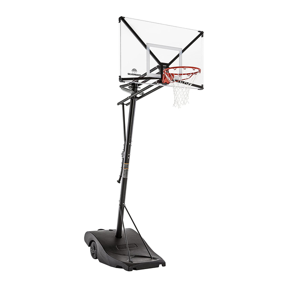
N X T 5 4
P O R T A B L E B A S K E T B A L L
MODEL NO.
B8401
2L-7611-02
2017 Escalade Sports

Advertisement

Table of Contents
loading
Need help?

Need help?

Do you have a question about the NXT54 and is the answer not in the manual?

Questions and answers

Ken
March 9, 2025

I need a replacement plug for the bottom of the base. What size do I need or where can I get one. Thanks

1 comments:
Mr. Anderson
May 14, 2025

The size of the replacement plug needed for the bottom of the base for the SilverBack NXT54 is not provided in the context.

This answer is automatically generated

Subscribe to Our Youtube Channel

Summary of Contents for SilverBack NXT54

  • Page 1 N X T 5 4 P O R T A B L E B A S K E T B A L L MODEL NO. B8401 Please Do Not Return This Product to the Store! Contact Escalade® Sports customer service department at: Phone: 1-888-USA-GOAL Toll-Free! Fax: 1-866-873-3536 Toll-Free! E-mail: customerservice@escaladesports.com...
  • Page 2 P R E - A S S E M B L Y T I P S 1. Read this manual carefully before starting assembly. Read each step completely before beginning each step. 2. Some smaller parts may be shipped inside larger parts. Check inside all parts and cartons before assembling or ordering parts.
  • Page 3: Safety Instructions

    SAFETY INSTRUCTIONS FAILURE TO FOLLOW THESE SAFETY INSTRUCTIONS MAY RESULT IN SERIOUS INJURY, PROPERTY DAMAGE AND WILL VOID WARRANTY. Owner must ensure that all players know and follow these rules for safe operation of the system. To ensure safety, do not attempt to assemble this system without following the instructions carefully. Check entire box and inside packing material for parts and/or additional instruction material.
  • Page 4 P A R T S L I S T ( N O T A C T U A L S I Z E ) BREAK AWAY RIM RIM NET SPRING COVER PLATE BACKBOARD ASSEMBLY 54 X 33 BALLAST 4A-8057-20 4A-8058-20 3F-6070-00 8S-7714-00 3M-8991-20...
  • Page 5 P A R T S L I S T ( N O T A C T U A L S I Z E ) (Actuator Bar Cap Pre-installed) BOARD ARM CAP 3M-9017-00 (QTY. 8) LOWER BOARD ARM UPPER BOARD ARM ACTUATOR BAR 1A-7907-20 (Pre-assembled to...
  • Page 6 P A R T S L I S T ( N O T A C T U A L S I Z E ) POLE CAP 3M-8997-00 (QTY. 1) (Pre-assembled to ACTUATOR GRIP ACTUATOR LOCK ASSEMBLY Top Pole) SPRING 3M-9034-00 4A-8141-20 5V-6040-00 (QTY.
  • Page 7 H A R D W A R E I D E N T I F I E R ( A C T U A L S I Z E ) (QTY. 3) HEX HEAD BOLT M10-1.5 X 220mm 1B-7085-00 (QTY. 1) HEX HEAD BOLT M10-1.5 X 210mm 1B-7080-00 (QTY.
  • Page 8 H A R D W A R E I D E N T I F I E R ( A C T U A L S I Z E ) Philips Head Screw M6-1 X 60mm HEX LOCK NUT M6-1 1B-7123-00 2B-6803-00 (QTY.
  • Page 9 HARDWARE NEEDED (ACTUAL SIZE) The following pages will have a picture of the Hardware Needed along with the Quantity, Part Number and Description. You can lay the hardware on the picture to identify the hardware. ASSEMBLY TIP HEX HEAD BOLT M10-1.5 X 65mm 1B-7081-00 (QTY.
  • Page 10 HARDWARE NEEDED (ACTUAL SIZE) HEX HEAD BOLT M10-1.5 X 210mm 1B-7080-00 (QTY. 1) HEX LOCK NUT M10-1.5 WASHER M10 2B-6801-00 2B-6800-00 (QTY. 1) (QTY. 2) 2. Attach lower pole (12) to lower assembly. Line up the holes in DETAIL A the four tubes and lower pole and attach hardware as shown in Detail A.
  • Page 11 HARDWARE NEEDED (ACTUAL SIZE) TOOLS NEEDED 16mm 16mm WASHER M10 HEX HEAD BOLT M10-1.5 X 25mm HEX LOCK NUT M10-1.5 2B-6800-00 2B-6801-00 1B-7082-00 (QTY. 2) (QTY. 4) (QTY. 2) 3. Finish securing lower pole (12) to lower assembly DETAIL A as shown.
  • Page 12 TOOLS NEEDED 4. Before Inserting Axle Bushings (5) into the lower assembly Steel Tube, align the bushings (5) so the groove goes over the tube weld seam without touching it. See Detail A & Detail B. Rubber 5. Use a wood block and Rubber Mallet to gently tap the Axle Wood Block Mallet Bushing into Steel Tube.
  • Page 13 6. Insert Axle (4) into lower assembly Steel tube until both ends of the Axle stick out about the same distance on each side. Steel Tube...
  • Page 14 NOTE: Inner Wheel Hub (6) and Outer wheel (8) are pre-assembled into Wheel (7) by the factory. If either of those parts have fallen out during shipping re-insert parts as shown in Detail A. 7. Slide Wheel (7) onto Axle (4). Repeat step to install the second wheel.
  • Page 15 HARDWARE NEEDED (ACTUAL SIZE) 8. Insert Axle Rod (9), through Washer (10) and into Wheel assembly and axle until it reaches the other side of the Axle and wheel. Have a Second person hold second Wheel. WASHER M10 X 30mm 2B-6795-00 (QTY.
  • Page 16 HARDWARE NEEDED (ACTUAL SIZE) TOOLS NEEDED 16mm 16mm HEX NUT M10-1.5 WASHER, LOCK INTERNAL-TOOTH WASHER M10 X 30mm 2B-6806-00 2B-6796-00 2B-6795-00 (QTY. 1) (QTY. 1) (QTY. 1) 9. Secure Axle Rod (9) with Washer (10), Lock Tooth Washer (43) and Hex Nut (11). Tighten Nut (11) until there’s about 1/4”...
  • Page 17 HARDWARE NEEDED 10. Unscrew the Wheel cap (41) and remove, O-ring (42) is pre-attached to Wheel cap. Fill both wheels with water until 75% full (approx. 1 gal.) and screw Wheel cap back into the wheel with Wheel Plug key (57). Make sure that O-ring is attached to Wheel Cap.
  • Page 18 HARDWARE NEEDED (ACTUAL SIZE) 12. Attach Left Brace tube (19) and Right brace Tube (18). Match up the green color coded stickers on the Right Brace tube and the lower pole and match the color stickers on the Left Brace tube HEX HEAD BOLT M8-1.25 X 65mm 1B-7077-00 and Lower Pole as shown in Detail A.
  • Page 19 HARDWARE NEEDED (ACTUAL SIZE) 13. Secure ballast to lower assembly as shown in Detail A. Finger Tighten hardware. HEX HEAD BOLT M8-1.25 X 65mm NOTE: If needed use your thumb to push bolt 1B-7077-00 Hex Lock Nut M8-1.25 forward (see Detail B) and then down (QTY.
  • Page 20 HARDWARE NEEDED (ACTUAL SIZE) 14. Position Middle pole (50) with the Warning label facing forward, then slide Middle pole into Lower pole (12). Make sure that all (QTY. 1) holes are aligned in both poles. HEX HEAD BOLT M10-1.5 X 110mm 1B-7079-00 15.
  • Page 21 HARDWARE NEEDED (ACTUAL SIZE) 16. Secure pole with hardware shown. Finger Tighten only. HEX HEAD BOLT M10-1.5 X 100mm 1B-7078-00 (QTY. 2) HEX NUT M10-1.5, WITH CAP WASHER _ CURVED M10 2B-6799-00 2B-6802-00 (QTY. 2) (QTY. 2) NOTE FINGER TIGHTEN ONLY! NOTE MAKE SURE HEADS OF THE BOLTS ARE INSERTED INTO...
  • Page 22 TOOLS NEEDED TIGHTEN THIS HARDWARE SECOND. 13mm 13mm 17. In this Step you will begin to tighten the hardware from previous steps in the following sequence: First tighten hardware shown in Detail A. Second, tighten hardware shown in Detail B. TIGHTEN HARDWARE UNTIL SNUG.
  • Page 23 TOOLS NEEDED 18. In this Step you will continue to tighten the hardware from previous steps: First tighten hardware shown in Detail A. Second, tighten hardware shown in Detail B. TIGHTEN HARDWARE TIGHT BUT DO NOT CRUSH TUBE. 16mm 17mm TIGHTEN THIS HARDWARE SECOND.
  • Page 24 HARDWARE NEEDED (ACTUAL SIZE) TOOLS NEEDED HEX HEAD BOLT M10-1.5 X 110mm 1B-7079-00 16mm 16mm (QTY. 2) 19. Attach the reinforcement plate (37) to the front of the pole (on the side that has the Warning label) with 2 bolts (22). HEX LOCK NUT M10-1.5 2B-6801-00 Hex heads should be facing front of the unit.
  • Page 25 HARDWARE NEEDED (ACTUAL SIZE) ACTUATOR ROLLER 3M-9035-00 (QTY. 1) HEX LOCK NUT M6-1 PHILIPS HEAD SCREW M6-1 X 60mm 2B-6803-00 1B-7123-00 (QTY. 1) (QTY. 1) TOOLS NEEDED 20. Insert Screw (46) through Actuator bracket, Actuator Roller (48) and through other side of Actuator bracket.
  • Page 26 TOOLS NEEDED NOTE: If your Top Pole (51) has the Pole Cap (38) pre-installed skip step 21. 21. Set the top pole (51) on a piece of cardboard (packing material) to protect the bottom of the pole. Insert the Pole Cap (38) at the top of the pole as shown in Detail A. Rubber 22.
  • Page 27 HARDWARE NEEDED (ACTUAL SIZE) 23. Insert hardware as shown in Detail A & Detail B. FINGER TIGHTEN ONLY. NOTE: MAKE SURE HEADS OF THE BOLTS ARE INSERTED INTO THE CUT OUT OF THE POLE. WASHER _ CURVED M10 HEX NUT M10-1.5, WITH CAP 2B-6802-00 2B-6799-00 (QTY.
  • Page 28 TOOLS NEEDED 24. In this Step you will begin to tighten the hardware from previous steps in the following sequence: First tighten hardware shown in Detail A. Second, tighten hardware shown in Detail B. 17mm TIGHTEN THIS HARDWARE SECOND. TIGHTEN THIS HARDWARE FIRST. NOTE MAKE SURE HEADS OF THE BOLTS ARE INSERTED INTO THE CUT OUT OF THE POLE, IF...
  • Page 29 NOTE: NOTE: Rest the system above the bolts of the actuator bracket so the ladder does not Prepare a flat area that is clear of debris. Keep children away from the damage the warning label. assembly area. Two capable adults are needed for the following steps. 25.
  • Page 30 HARDWARE NEEDED (ACTUAL SIZE) 28. With a helper still holding the pole, attach the arms to upper pole as shown in Detail A-C. Finger Tighten Nuts (29) only, you will tighten this hardware in the next page. WASHER M12 X 24mm OD HEX LOCK NUT M12-1.75 2B-6804-00 2B-6805-00...
  • Page 31 HARDWARE NEEDED (ACTUAL SIZE) TOOLS NEEDED HEX HEAD BOLT M10-1.5 X 220mm 1B-7085-00 (QTY. 2) 16mm WASHER M10 HEX LOCK NUT M10-1.5 2B-6800-00 2B-6801-00 WASHER, NYLON (QTY. 4) 3M-9000-00 (QTY. 2) 16mm 19mm (QTY. 4) 29. Attach Backboard Box (26) to lower and upper arms as shown in Detail A & B. Make sure to put a (27) Nylon washer in between the Arms and the Backboard Box.
  • Page 32 30. Insert one end of the spring (35) into Spring loop on the upper Arms (52). CAUTION: 31. With the help of another person attach Spring (35) to BE CAREFUL WITH THE SPRING WHEN PULLING loop on the bottom board arms (49). With one hand IT BACK, KEEP FINGERS AWAY FROM COILS.
  • Page 33 HARDWARE NEEDED 32. With the assembly still facing down, attach the backboard as shown. Have a person hold the backboard while you insert the Hitch pins (33) into the backboard supports. See Details A & B. The hitch pins will keep the backboard in place and will be HITCH PIN completely secure once the Rim is attached.
  • Page 34 HARDWARE NEEDED (ACTUAL SIZE) TOOLS NEEDED NOTE: Take protective coating off the backboard before attaching the Rim. 33. With the assembly still facing down, attach the Rim to the Backboard. Have a person hold the Rim in 16mm socket place while you place Washers (23) and Nuts (24) with 3”...
  • Page 35 TOOLS NEEDED HARDWARE NEEDED 34. Attach Net (58) to Rim (44) by looping net over metal horn and tucking under as shown in Detail A. 35. Attach Spring Cover Plate (60) to Rim with two Screws (59). See Detail B &C. FLAT HEAD SCREW M4-0.7 X 10mm Phillips 1B-7100-00...
  • Page 36 36. Slide the Actuator Bar (53) through the Actuator Bracket, release the lever by pressing down and holding while inserting the Actuator Bar. See Detail A & B. 37. Engage the lock by letting go of the lever and allow actuator to lock into the bracket.
  • Page 37 HARDWARE NEEDED (ACTUAL SIZE) TOOLS NEEDED HEX HEAD BOLT M10-1.5 X 220mm 1B-7085-00 16mm (QTY. 1) WASHER M10 HEX LOCK NUT M10-1.5 2B-6800-00 2B-6801-00 (QTY. 1) 16mm (QTY. 2) 38. Attach other end of the Actuator Bar (#53) to the lower arms, as shown. You may have to pivot the arms to align actuator.
  • Page 38 HARDWARE NEEDED TOOLS NEEDED 39. Insert Actuator Grip (#31) into Actuator bar until the handle is flush with the Actuator bar, then line up the holes in the grip with the holes in the actuator bar and secure with two Screws (#32) as Rubber shown in Detail A.
  • Page 39 NOTE: This is a good time to clean the backboard (if needed). Use a damp microfiber towel or soft cotton cloth to clean the backboard. Do not use paper towels, harsh chemicals or anything that could potentially damage your backboard. 40.
  • Page 40 42. Carefully move the system where you would like to place it and then Fill the Ballast about 75% full (approx. 25 gal.) with water. Make sure that the Ballast Cap washer (14) is in place before Screwing cap (13) in place. NOTE: Do not overfill ballast.
  • Page 41 Any labor costs, travel expenses and any other changes involved in the removal, installation or replacement of the defective/repaired parts from/to your Silverback System will be the purchaser’s responsibility. Shipping charges for replaced or warranted merchandise sent back to the customer from Escalade Sports factory must be prepaid by the customer in advance.

This manual is also suitable for:

B8401

Table of Contents

Save PDF