Table of Contents
Advertisement
Advertisement
Table of Contents

Related Manuals for Mercury Big Tiller


Summary of Contents for Mercury Big Tiller
- Page 1 Operation Manual...
-
Page 3: Table Of Contents
Tiller Handle Components Tiller Handle Component Location..............1 Lanyard Stop Switch Operation Lanyard Stop Switch................... 2 Tiller Handle Adjustments Adjustments......................5 Gear Shifting Gear Shifting....................... 9 Troll Control (if Equipped) Troll Control...................... 10 Power Trim Power Trim....................... 11 Operation General Information..................12 Prestarting Instructions.................. -
Page 5: Tiller Handle Components
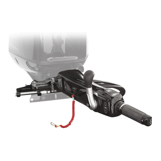
TILLER HANDLE COMPONENTS Tiller Handle Component Location 33022 Power trim switch Throttle grip Steering actuator adjustment collar (power steering models) Throttle grip friction knob Tiller handle lock knob Tiller handle tilt friction adjustment jam nut 65276 Ignition key switch Lanyard stop switch Lanyard Gear shift handle Troll speed control switch (if equipped) -
Page 6: Lanyard Stop Switch Operation
LANYARD STOP SWITCH OPERATION Lanyard Stop Switch The purpose of a lanyard stop switch is to turn off the engine when the operator moves far enough away from the operator's position (as in accidental ejection from the operator's position) to activate the switch. Tiller handle outboards and some remote control units are equipped with a lanyard stop switch. - Page 7 LANYARD STOP SWITCH OPERATION Important Safety Information: The purpose of a lanyard stop switch is to stop the engine when the operator moves far enough away from the operator's position to activate the switch. This would occur if the operator accidentally falls overboard or moves within the boat a sufficient distance from the operator's position.
- Page 8 LANYARD STOP SWITCH OPERATION KEEP THE LANYARD STOP SWITCH AND LANYARD CORD IN GOOD OPERATING CONDITION Before each use, check to ensure the lanyard stop switch works properly. Start the engine and stop it by pulling the lanyard cord. If the engine does not stop, have the switch repaired before operating the boat.
-
Page 9: Tiller Handle Adjustments
TILLER HANDLE ADJUSTMENTS Adjustments THROTTLE GRIP FRICTION ADJUSTMENT Turn the throttle grip friction knob to set and maintain the throttle at the desired speed. The throttle grip friction knob can be adjusted to increase or decrease the amount of effort needed to rotate the throttle grip. Turn the knob clockwise to tighten friction or counterclockwise to loosen friction. - Page 10 TILLER HANDLE ADJUSTMENTS TILLER HANDLE TILT FRICTION ADJUSTMENT The tiller handle pivot bolt can be adjusted to increase or decrease the amount of effort needed to move the tiller handle up and down. Loosen the jam nut on the end of the pivot bolt and tighten or loosen the pivot bolt to obtain the desired friction setting on the tiller handle.
- Page 11 TILLER HANDLE ADJUSTMENTS TILLER HANDLE TILT LOCK—3 POSITION HANDLE The tilt lock feature allows for the tiller handle to be tilted up and locked in either the mid tilt angle position or full tilt angle position. When using the tilt lock feature, move the tiller handle to the desired position and rotate the tilt lock knob clockwise so that the cross pin will access the through slot.
- Page 12 TILLER HANDLE ADJUSTMENTS TILLER HANDLE TILT LOCK—2 POSITION HANDLE The tilt lock feature allows for the tiller handle to be tilted up and locked in the full tilt angle position. When using the tilt lock feature, move the tiller handle to the full tilt angle position and rotate the tilt lock knob clockwise so that the cross pin will access the through slot.
-
Page 13: Gear Shifting
GEAR SHIFTING Gear Shifting IMPORTANT: Observe the following: • Never shift outboard into gear unless engine speed is at idle. • Do not shift outboard into reverse when the engine is not running. • Your outboard has three gear shift positions to provide operation: forward (F), neutral (N), and reverse (R). -
Page 14: Troll Control (If Equipped)
TROLL CONTROL (IF EQUIPPED) Troll Control Troll control allows the operator to maintain a set trolling speed without using the throttle. Refer to the following table for the trolling speed range. Trolling Speed Range 30–60 hp FourStroke 700–1000 RPM 75–150 hp FourStroke 550–1000 RPM 75–125 OptiMax 650–1000 RPM... -
Page 15: Power Trim
POWER TRIM Power Trim The power trim switch allows the operator to adjust the position of the outboard. Refer to Power Trim Operation in the outboard owner's manual. 33041 Power trim switch... -
Page 16: Operation
If the tiller handle causes interference when the outboard is tilted up to the full position, a tilt limit kit is available for models 75 hp and higher through Mercury Marine. This kit will limit the upward tilting range of the outboard. Contact your authorized dealer. -
Page 17: Starting The Engine
OPERATION Starting the Engine 1. Open the fuel tank vent screw (in filler cap) on the manual venting type fuel tanks. 19748 2. Models with primer bulb ‑ Position the fuel line primer bulb so the arrow on the side of the bulb is pointing up. Squeeze the fuel line primer bulb until it feels firm. - Page 18 OPERATION 4. Shift outboard to neutral ("N") position. 33038 5. Rotate the throttle grip clockwise to the "START/SHIFT" position. 6. Starting a flooded engine ‑ Advance the throttle grip to half throttle position. 65328 Start/Shift NOTE: For initial start of a new engine, or for an engine that ran out of fuel or was drained of fuel, the fuel system should be filled by following the procedure in the Starting the Outboard section of the outboard owner's manual.
-
Page 19: Stopping The Engine
OPERATION 8. 150 FourStroke and DTS models ‑ Turn the ignition key to the "START" position and release the key. The electronic starting system will automatically crank the engine for starting. If the engine fails to start, the engine will stop cranking. Turn the key to the "START" position again until the engine starts. -
Page 20: Auxiliary Light (If Equipped)
AUXILIARY LIGHT (IF EQUIPPED) Auxiliary Light (if Equipped) An auxiliary light is located on the bottom of the tiller handle. The light can be turned on whenever the ignition key switch is in the "ON" or "RUN" position. Turn the light on or off using the light switch in the light housing. Auxiliary light Light switch 33042...
Need help?
Do you have a question about the Big Tiller and is the answer not in the manual?
Questions and answers
with a big tiller handle, is there different locking positions other that the 2 stow positions?
Yes, the Mercury Big Tiller handle has a tilt lock feature with two positions: a mid-tilt angle position and a full tilt angle position. The handle can be locked in the full tilt angle position by rotating the tilt lock knob clockwise and engaging the lock. It can be released by pulling out the tilt lock knob and turning it counterclockwise.
This answer is automatically generated