Table of Contents
Advertisement
Quick Links
Advertisement
Table of Contents

Related Manuals for Clevo W245CUQ


Summary of Contents for Clevo W245CUQ
- Page 1 W245CUQ/W246CUQ/W247CUQ/W24ACU/W24BCU...
- Page 3 Preface Notebook Computer W245CUQ/W246CUQ/W247CUQ/W24ACU/W24BCU Service Manual...
- Page 4 Preface Notice The company reserves the right to revise this publication or to change its contents without notice. Information contained herein is for reference only and does not constitute a commitment on the part of the manufacturer or any subsequent ven- dor.
- Page 5 This manual is intended for service personnel who have completed sufficient training to undertake the maintenance and inspection of personal computers. It is organized to allow you to look up basic information for servicing and/or upgrading components of the W245CUQ/ W246CUQ/W247CUQ/W24ACU/W24BCU series notebook PC.
- Page 6 Preface IMPORTANT SAFETY INSTRUCTIONS Follow basic safety precautions, including those listed below, to reduce the risk of fire, electric shock and injury to per- sons when using any electrical equipment: 1. Do not use this product near water, for example near a bath tub, wash bowl, kitchen sink or laundry tub, in a wet basement or near a swimming pool.
- Page 7 Preface Instructions for Care and Operation The notebook computer is quite rugged, but it can be damaged. To prevent this, follow these suggestions: Don’t drop it, or expose it to shock. If the computer falls, the case and the components could be damaged. Do not expose the computer Do not place it on an unstable Do not place anything heavy...
- Page 8 Preface Avoid interference. Keep the computer away from high capacity transformers, electric motors, and other strong mag- netic fields. These can hinder proper performance and damage your data. Take care when using peripheral devices. Use only approved brands of Unplug the power cord before peripherals.
- Page 9 Preface Battery Precautions • Only use batteries designed for this computer. The wrong battery type may explode, leak or damage the computer. • Do not continue to use a battery that has been dropped, or that appears damaged (e.g. bent or twisted) in any way. Even if the computer continues to work with a damaged battery in place, it may cause circuit damage, which may possibly result in fire.
- Page 10 Preface Related Documents You may also need to consult the following manual for additional information: User’s Manual on CD This describes the notebook PC’s features and the procedures for operating the computer and its ROM-based setup pro- gram. It also describes the installation and operation of the utility programs provided with the notebook PC. System Startup 1.
-
Page 11: Table Of Contents
Introduction ..........1-1 Top (W24ACU, W24BCU) ............A-5 Bottom 3.5W (W245CUQ, W246CUQ) ........A-6 Overview ..................1-1 Bottom 3.5W - No SIM (W245CUQ, W246CUQ) ....... A-7 Models Differences .................1-1 Bottom 3.5W (W24ACU, W24BCU) ..........A-8 Specifications ..................1-2 Bottom 6.5W (W245CUQ, W246CUQ) ........A-9 External Locator - Top View with LCD Panel Open ......1-4... - Page 12 Preface CARD READER JMB261C ............B-18 KBC-ITE IT8518E, SPI ............... B-19 3G, WLAN, BT ................B-20 USB PORT & USB CHARGER ..........B-21 CONN, CCD, LED ............... B-22 PWR VDD3, VDD5V, SYS15V ..........B-23 PWR SW, 3V, 5V, 3VS, 5VS, 1.5VS .......... B-24 PWR 1.05VS ................
-
Page 13: Introduction
Chapter 1: Introduction Overview This manual covers the information you need to service or upgrade the W245CUQ/W246CUQ/W247CUQ/W24ACU/ W24BCU series notebook computer. Information about operating the computer (e.g. getting started, and the Setup utility) is in the User’s Manual. Information about drivers (e.g. VGA & audio) is also found in User’s Manual. That manual is shipped with the computer. -
Page 14: Specifications
Introduction Specifications Processor Video Adapter for N2800 Processor Intel® Atom® Processor N2600 Intel® GMA 3650@640MHz Video Integrated with the N2800 Processor 1.60 GHz, 1MB L2 Cache & 800MHz FSB, TDP 3.5W - BGA Package, 32nm (32 Nanometer) Process Total Available Graphics Memory of up to 384MB Technology Supports DirectX®... - Page 15 Introduction Keyboard & Pointing Device Communication Battery Isolated WinKey Keyboard 10Mb/100Mb Base-TX Ethernet LAN Removable 6 Cell Smart Lithium-Ion Battery Pack 48.84WH Built-in TouchPad with Multi-Gesture Functionality 802.11b/g/n Wireless LAN Half Mini-Card Module Some Designs Only: (Factory Option) Removable 3 Cell Smart Lithium-Ion Battery Pack Three Instant Keys for WWW, E-Mail &...
-
Page 16: External Locator - Top View With Lcd Panel Open
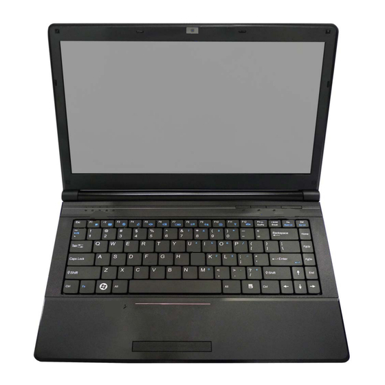
Introduction External Locator - Top View with LCD Panel Open Figure 1 Top View 1. Optional Built-In PC Camera 2. LCD 3. Power Button Hot Key Buttons (for some designs only) 5. LED Status Indicators 6. Keyboard 7. Built-In Microphone 8. -
Page 17: External Locator - Front & Right Side Views
Introduction External Locator - Front & Right side Views Figure 2 Front Views 1. LED Power Indicators Figure 3 Right Side Views 1. Microphone-In Jack 2. Headphone-Out Jack 3. USB 2.0 Port 4. Optical Device Drive Bay 5. Security Lock Slot External Locator - Front &... -
Page 18: External Locator - Left Side & Rear View
Introduction External Locator - Left Side & Rear View Figure 4 Left Side View 1. DC-In Jack 2. External Monitor Port 3. RJ-45 LAN Jack 4. HDMI-Out Port 5. 2 * USB 2.0 Ports 6. Vent 7. Multi-in-1 Card Reader Figure 5 Rear View 1. -
Page 19: External Locator - Bottom View
Introduction External Locator - Bottom View Figure 6 Bottom View 1. Battery 2. Component Bay Cover 3. Vent/Fan Intake/ Outlet 4. Hard Disk Bay Cover 5. 3.75G/HSPA USIM Card Cover (optional) Overheating To prevent your com- puter from overheating make sure nothing... -
Page 20: Mainboard Overview - Top (Key Parts)
Introduction Mainboard Overview - Top (Key Parts) Figure 7 Mainboard Top Key Parts 1. JMC261 2. ITE 8518E 3. AZALIA Codec 1 - 8 Mainboard Overview - Top (Key Parts) -
Page 21: Mainboard Overview - Bottom (Key Parts)
Introduction Mainboard Overview - Bottom (Key Parts) Figure 8 Mainboard Bottom Key Parts 1. Memory Slots DDR3 SO-DIMM 2. Accelerated Processing Unit 3. Intel NM10 PCH 4. CMOS Battery 5. Mini-Card Connector (WLAN Module) 6. Card Reader Socket Mainboard Overview - Bottom (Key Parts) 1 - 9... -
Page 22: Mainboard Overview - Top (Connectors)
Introduction Mainboard Overview - Top (Connectors) Figure 9 Mainboard Top Connectors 1. HDMI-Out Port 2. USB Port 2.0 3. Speaker Cable Connector 4. Microphone Cable Connector 5. Audio Board Connector 6. TouchPad Cable Connector 1 7. Keyboard Cable Connector 8. Switch Board Cable Connector 1 - 10 Mainboard Overview - Top (Connectors) -
Page 23: Mainboard Overview - Bottom (Connectors)
Introduction Mainboard Overview - Bottom (Connectors) Figure 10 Mainboard Bottom Connectors 1. Battery Connector 2. ODD Connector 3. HDD Connector 4. CPU Fan Cable Connector 5. RJ-45 LAN Jack 6. External Monitor Port 7. DC-In Jack 8. CCD Cable Connector 9. - Page 24 Introduction 1 - 12...
-
Page 25: Disassembly
Disassembly Chapter 2: Disassembly Overview This chapter provides step-by-step instructions for disassembling the W245CUQ/W246CUQ/W247CUQ/W24ACU/ W24BCU series notebook’s parts and subsystems. When it comes to reassembly, reverse the procedures (unless other- wise indicated). We suggest you completely review any procedure before you take the computer apart. -
Page 26: Maintenance Tools
Disassembly NOTE: All disassembly procedures assume that the system is turned OFF, and disconnected from any power supply (the battery is removed too). Maintenance Tools The following tools are recommended when working on the notebook PC: • M3 Philips-head screwdriver •... -
Page 27: Maintenance Precautions
Disassembly Maintenance Precautions The following precautions are a reminder. To avoid personal injury or damage to the computer while performing a re- moval and/or replacement job, take the following precautions: Power Safety Warning 1. Don't drop it. Perform your repairs and/or upgrades on a stable surface. If the computer falls, the case and other Before you undertake components could be damaged. -
Page 28: Disassembly Steps
Disassembly Disassembly Steps The following table lists the disassembly steps, and on which page to find the related information. PLEASE PERFORM THE DISASSEMBLY STEPS IN THE ORDER INDICATED. To remove the Battery: To remove the Keyboard: 1. Remove the battery page 2 - 5 1. -
Page 29: Removing The Battery
Disassembly Removing the Battery Figure 1 Battery Removal 1. Turn the computer off, and turn it over. 2. Slide the latch in the direction of the arrow (Figure 1a a. Slide the latch and hold it 3. Slide the latch in the direction of the arrow, and hold it in place (Figure 1a in place. -
Page 30: Removing The Hard Disk Drive
Disassembly Removing the Hard Disk Drive The hard disk drive can be taken out to accommodate other 2.5" serial (SATA) hard disk drives with a height of 9.5mm Figure 2 (h). Follow your operating system’s installation instructions, and install all necessary drivers and utilities (as outlined in HDD Assembly Chapter 4 of the User’s Manual) when setting up a new hard disk. - Page 31 Disassembly 3. Remove the hard disk bay cover (Figure 3b Figure 3 4. Grip the tab and slide the hard disk in the direction of arrow (Figure 3c HDD Assembly 5. Lift the hard disk assembly out of the bay (Figure 3d Removal (cont’d.) 6.
-
Page 32: Removing The Optical (Cd/Dvd) Device
Disassembly Removing the Optical (CD/DVD) Device Figure 4 Optical Device 1. Turn off the computer, remove the battery (page 2 - Removal 2. Locate the component bay cover and remove screws (Figure 4a 3. Carefully (a fan and cable are attached to the under side of the cover) lift up the bay cover. a. -
Page 33: Removing The System Memory (Ram)
Disassembly Removing the System Memory (RAM) Figure 5 RAM Module The computer has one memory socket for 200 pin Small Outline Dual In-line Memory Modules (SO-DIMM) supporting Removal DDR3 1333/ 1066MHz. The main memory can be expanded up to 4GB. The SO-DIMM modules supported are 1GB, 2GB and 4GB and DDRIII Modules. -
Page 34: Removing The Wireless Lan Module
Disassembly Removing the Wireless LAN Module Figure 6 Wireless LAN 1. Turn off the computer, remove the battery (page 2 - 5) and the component bay cover (page 2 - Module Removal 2. The Wireless LAN module will be visible at point on the mainboard. -
Page 35: Removing The 3.75G Module
Disassembly Removing the 3.75G Module Figure 7 3.75G Module 1. Turn off the computer, remove the battery (page 2 - 5) and the component bay cover (page 2 - Removal 2. Carefully disconnect the cable , then remove the screw from the module socket. -
Page 36: Removing The Keyboard
Disassembly Removing the Keyboard Figure 8 Keyboard Removal 1. Turn off the computer, and remove the battery (page 2 - 2. Remove screws from the bottom of the computer. Press at points to unsnap the LED cover module a. Remove screws from the bottom of the computer. -
Page 37: Part Lists
Part Lists Appendix A: Part Lists This appendix breaks down the W245CUQ/W246CUQ/W247CUQ/W24ACU/W24BCU series notebook’s construction into a series of illustrations. The component part numbers are indicated in the tables opposite the drawings. Note: This section indicates the manufacturer’s part numbers. Your organization may use a different system, so be sure to cross-check any relevant documentation. -
Page 38: Part List Illustration Location
Part Lists Part List Illustration Location The following table indicates where to find the appropriate part list illustration. Table A- 1 Part List Illustration Location Parts W245CUQ W246CUQ W247CUQ W24ACU W24BCU page A - 3 page A - 4 page A - 5 Bottom (3.5W) -
Page 39: Top (W245Cuq, W246Cuq
Part Lists Top (W245CUQ, W246CUQ) Figure A - 1 Top (W245CUQ, W246CUQ) 黑色 (今皓) (今皓) (灰色) ( 尚 盟) 度 黑色 頭徑 頭厚 號 導電布 Top (W245CUQ, W246CUQ) A - 3... -
Page 40: Top (W247Cuq
Part Lists Top (W247CUQ) Figure A - 2 Top (W247CUQ) 黑色 今皓 今皓 今皓 (灰色) 度 黑色 非耐落 A - 4 Top (W247CUQ) -
Page 41: Top (W24Acu, W24Bcu
Part Lists Top (W24ACU, W24BCU) Figure A - 3 Top (W24ACU, W24BCU) 黑色 灰色 尚盟 頭徑 頭厚 號穴 鍍白鎳 I頭 Top (W24ACU, W24BCU) A - 5... -
Page 42: Bottom 3.5W (W245Cuq, W246Cuq
Part Lists Bottom 3.5W (W245CUQ, W246CUQ) Figure A - 4 Bottom 3.5W (W245CUQ, W246CUQ) A - 6 Bottom 3.5W (W245CUQ, W246CUQ) -
Page 43: Bottom 3.5W - No Sim (W245Cuq, W246Cuq
Part Lists Bottom 3.5W - No SIM (W245CUQ, W246CUQ) Figure A - 5 Bottom 3.5W (W245CUQ, W246CUQ) Bottom 3.5W - No SIM (W245CUQ, W246CUQ) A - 7... -
Page 44: Bottom 3.5W (W24Acu, W24Bcu
Part Lists Bottom 3.5W (W24ACU, W24BCU) Figure A - 6 Bottom 3.5W (W24ACU, W24BCU) A - 8 Bottom 3.5W (W24ACU, W24BCU) -
Page 45: Bottom 6.5W (W245Cuq, W246Cuq
Part Lists Bottom 6.5W (W245CUQ, W246CUQ) Figure A - 7 Bottom 6.5W (W245CUQ, W246CUQ) Bottom 6.5W (W245CUQ, W246CUQ) A - 9... -
Page 46: Bottom 6.5W - No Sim (W245Cuq, W246Cuq
Part Lists Bottom 6.5W - No SIM (W245CUQ, W246CUQ) Figure A - 8 Bottom 6.5W (W245CUQ, W246CUQ) A - 10 Bottom 6.5W - No SIM (W245CUQ, W246CUQ) -
Page 47: Bottom 6.5W (W24Acu, W24Bcu
Part Lists Bottom 6.5W (W24ACU, W24BCU) Figure A - 9 Bottom 6.5W (W24ACU, W24BCU) Bottom 6.5W (W24ACU, W24BCU) A - 11... -
Page 48: Lcd (W245Cuq
Part Lists LCD (W245CUQ) Figure A - 10 LCD (W245CUQ) 銘板 精乘 精乘 A - 12 LCD (W245CUQ) -
Page 49: Lcd (W246Cuq
Part Lists LCD (W246CUQ) Figure A - 11 LCD (W246CUQ) 銘板 (華力) LCD (W246CUQ) A - 13... -
Page 50: Lcd (W247Cuq
Part Lists LCD (W247CUQ) Figure A - 12 LCD (W247CUQ) 非耐落 無鉛 設變 (華力) 精乘 A - 14 LCD (W247CUQ) -
Page 51: Lcd (W24Acu, W24Bcu
Part Lists LCD (W24ACU, W24BCU) Figure A - 13 LCD (W24ACU, W24BCU) 銘板 LCD (W24ACU, W24BCU) A - 15... -
Page 52: Sata-Dvd (W245Cuq, W246Cuq
Part Lists SATA-DVD (W245CUQ, W246CUQ) Figure A - 14 SATA-DVD (W245CUQ, W246CUQ) *(非耐落) 無鉛 A - 16 SATA-DVD (W245CUQ, W246CUQ) -
Page 53: Sata-Dvd (W24Acu, W24Bcu
Part Lists SATA-DVD (W24ACU, W24BCU) Figure A - 15 SATA-DVD (W24ACU, W24BCU) *(非耐落) SATA-DVD (W24ACU, W24BCU) A - 17... - Page 54 Part Lists A - 18...
- Page 55 Schematic Diagrams Appendix B: Schematic Diagrams This appendix has circuit diagrams of the W245CUQ/W246CUQ/W247CUQ/W24ACU/W24BCU notebook’s PCB’s. The following table indicates where to find the appropriate schematic diagram. Diagram - Page Diagram - Page Diagram - Page Table B - 1...
-
Page 56: Schematic Diagrams
Schematic Diagrams System Block Diagram VDD3,VDD5 CLEVO Cedar Trail-M System Block Diagram MB:6-71-W24C0-D02A (W24ACU) DDR3 One Channel 1GB & 2GB 3.3V,5V,3VS,5VS,1.8VS AUDIO: 6-71-W24C8-D02(W24ACU) 14.318 MHz SODIMM2¤@©w-n¤W Colck Generator SO-DIMM2 IDT 9VRS4338 PWR SW:6-71-W24ES-D03(W244EU) 17.1mm*8.1mm*1.2mm 1.05VS,1.5VS Use EDP LCD TSSOP 64PIN... -
Page 57: Cedarview Cpu Part-D
Schematic Diagrams CEDARVIEW CPU PART-D U15D CEDARVIEW 1.8VS 1.8VS 1.10 1.05VS H_SMI# H_SMI# *1K_04 RSVD_L26 SMI# H_SMI# H_RSVD_L27 H_NMI H_NMI *220_04 *220_04 *1K_04 STRAP_L27 NMI/LINT10 H_NMI H_RSVD_K28 H_A20M# H_A20M# 1K_04 STRAP_K28 RSVD_C18 H_A20M# 10 H_RSVD_K28 H_RSVD_L27 H_STPCLK# H_STPCLK# *1K_04 RSVD_K25 STPCLK# H_STPCLK# 10 RSVD_J28... -
Page 58: Cedarview Cpu Part-A-C-F
Schematic Diagrams CEDARVIEW CPU PART-A-C-F DM I Signal Gr oup Zd iff = 80 Ohm ¡Ó17.5% U15A CEDARVIEW le ng th =bre ak out(<=500m ils )+(<= 6000 m ils ) C305 0.1u_10V_X7R_04 DMI_RXP_0 1.10 DMI_TXP_0 DMI_ICH_IT_MR0_D P DMI_R XP0 DMI_TXP0 DMI_IC H_MT_IR0_DP 9 DMI_RXN_0 DMI_TXN_0... -
Page 59: Cedarview Cpu Part-B
Schematic Diagrams CEDARVIEW CPU PART-B M_A_DQ[63:0] 6,7 U15B M_A_A[15:0] Zdiff = 50 Ohm ¡Ó 10 M_A_A0 AK14 CEDARVIEW Y 30 M_A_DQ0 DD R3_MA0 DDR 3_D Q0 M_A_A1 AK16 Y 29 M_A_DQ1 DD R3_MA1 DDR 3_D Q1 M_A_A2 AJ14 AC30 M_A_DQ2 U15F 1.10 AJ16... -
Page 60: Cedarview Cpu Part-E
Schematic Diagrams CEDARVIEW CPU PART-E U15E CEDARVIEW VCORE 1.05VS_RSENSE AA14 *HCB1005KF-121T20_short 1.10 1.05VS VCCADDR_1 VCC_CPU_01 AA16 VCCADDR_2 VCC_CPU_02 1.05VS_EAST C123 C114 C333 C110 VCCADDR_3 VCC_CPU_03 *HCB1005KF-121T20_short 1.05VS VCCADDR_4 VCC_CPU_04 *0.1u_16V_Y 5V_04 *0.1u_16V_Y 5V_04 *0.1u_16V_Y 5V_04 *0.1u_16V_Y 5V_04 VCC_CPU_05 1.05VS_VCCDDR 1.05VS_RSENSE VCCRAMXXX_1 VCC_CPU_06 VCCRAMXXX_2... -
Page 61: Ddr3 So-Dimm 1
Schematic Diagrams DDR3 SO-DIMM 1 One DIMM ¤£¤W¥ó SO-DIMM 1 CLOSE TO CPU JD IMM1A M_A_A[15:0] M_A_D Q[63:0] 4,7 M_A_A0 M_A_DQ0 JD IMM1B M_A_A1 M_A_DQ1 M_A_A2 M_A_DQ2 M_A_A3 M_A_DQ3 1.5V M_A_A4 M_A_DQ4 M_A_A5 M_A_DQ5 VD D1 VSS16 M_A_A6 M_A_DQ6 VD D2 VSS17 M_A_A7 M_A_DQ7... - Page 62 Schematic Diagrams DDR3 SO-DIMM 2 SO-DIMM 2 JDIMM2A M_A_A[15:0] M_A_D Q[63:0] 4,6 M_A_A0 M_A_DQ0 JD IMM2B M_A_A1 M_A_DQ1 M_A_A2 M_A_DQ2 M_A_A3 M_A_DQ3 1.5V M_A_A4 M_A_DQ4 M_A_A5 M_A_DQ5 VDD1 VSS16 M_A_A6 M_A_DQ6 VDD2 VSS17 M_A_A7 M_A_DQ7 C 86 *10p_50V_NPO_04 VDD3 VSS18 M_CLK_DDR2 M_CLK_DD R2# M_A_A8...
-
Page 63: Idt Clock
Schematic Diagrams IDT CLOCK 1.5VS_C LK 1.5VS *HC B1608KF-121T25_short 3.3VS 3.3VS_C LK *HCB1608KF-121T25_short 1.05VS_CLK 1.05VS *H CB1608KF-121T25_short PLACE CRYSTAL WITHIN IDT 9VR S4338 500 M ILS OF CK505 XTAL_IN XTAL_OUT XTAL_IN XTAL_OUT FSX8L_14.31818MHz 10 m ils C342 C 345 DOT Clock - 96MHz Sheet 8 of 31 CLK_DOT96 3 DOT96_LRS/SRC4_LRS... -
Page 64: Tigerpoint Part-A-B
Schematic Diagrams Tigerpoint PART-A-B USB Signal Gr oup Zdiff = 90 Ohm ¡Ó17.5% s ignal / s pace : 4.5 / 6 m ils U19B U19A USB0 USB Port 0 Tigerpoint Tigerpoint USB1 USB Port 1 DMI_ICH_MT_IR0_DN DMI0RXN USBP0N USB_PN0 20 DMI_ICH_MT_IR0_DP USB_PP0 20 DMI0RXP... -
Page 65: Tigerpoint Part-C
Schematic Diagrams Tigerpoint PART-C SATA Signal Group Zdiff = 95 Ohm ¡Ó17.5% signal / s pace : 4 / 6.5 m ils U19C Tigerpoint SATARXN0 15 RSVD03 SATA0RXN AE20 RSVD04 SATA0RXP SATARXP0 15 AD17 SATA HDD RSVD05 SATA0TXN SATATXN0 15 AC15 RSVD06 SATA0TXP... -
Page 66: Tigerpoint Part-D
Schematic Diagrams Tigerpoint PART-D 3.3VS 3.3V U19D R303 *1K_04 AZ_SDOUT GPIO0 KBC_SMI# PCIE PORT CONF BIT1 Tigerpoint LDRQ1#/GPIO23 BM_BUSY#/GPIO0 KBC_SWI# 15,18 LPC_AD0 LAD0/FWH0 GPIO6 R304 *1K_04 AZ_SYNC LPC Signal Gr oup KBC_SCI# 15,18 LPC_AD1 LAD1/FWH1 GPIO7 PCIE PORT CONF BIT0 Zo = 55 Ohm GPIO8 LCD_PID0... -
Page 67: Tigerpoint Part-E-F
Schematic Diagrams Tigerpoint PART-E-F 3.3VS 3.3V R119 R157 100_1%_04 RB751S-40C2 10_1%_04 RB751S-40C2 10mA C164 C161 C207 C198 1u_6.3V_X5R_04 *0.1u_10V_X5R_04 *1u_6.3V_X5R_04 0.1u_10V_X5R_04 1.5VS 50m A *HCB1005KF-121T20_short C202 C189 10u_6.3V_X5R_06 0.1u_16V_Y5V_04 U19F Sheet 12 of 31 VCC_RTC 1.5VS U19E Tigerpoint 2m A *HCB1005KF-121T20_short VSS01 VCC5REF... -
Page 68: Lvds, Inverter
Schematic Diagrams LVDS, INVERTER VLED PANEL CONNECTOR PJ18 OPEN -2m m D02A Z1304 3.3VS_LCD Follow Common Design 7/25 3.3V Follow W210CUQ R214 *P2003EVG C290 *0.22u_50V_Y 5V_06 *220_06 R210 R211 R221 10K_04 10K_04 R224 *10K_04 *1M_04 NB_ENAVDD# *MTD N7002ZH S6R R225 *100K_04 C421 *27p_50V_NPO_04... -
Page 69: Crt, Hdmi
Schematic Diagrams CRT, HDMI EM I FCM1005MF-600T01 J_CRT1 CRT_RED *FCM1005MF-600T01-short 108AH15FST04A1CC DAC_RED FRED FCM1005MF-600T01 CRT_GREEN *FCM1005MF-600T01-short FGRN DAC_GREEN FBLU FCM1005MF-600T01 CRT_BLUE *FCM1005MF-600T01-short DAC_BLUE CRT DAC Signal Group CRT_DDCADAT CRT_RED,CRT_GREEN,CRT_BLUE CRT_HSY NC_R VGA RGB r e sistors cols e to Conne cter CRT_VSYNC_R Zo = 50 Ohm ¡Ó15% signal : 4 m ils... -
Page 70: Tpm, Sata Hdd, Odd, Fan
Schematic Diagrams TPM, SATA HDD, ODD, FAN 3.3VS 3.3VS TPM 1.2 (¤£¤W¥ó,D01,»â®Æ¥x¥_ÅçÃÒ) TPM_PP R162 *10K_04 C206 C211 C229 C210 TPM_BADD R158 *10K_04 11,18 LPC_AD0 LAD0 VDD1 *0.1u_16V_Y5V_04 *0.1u_16V_Y5V_04 *0.1u_16V_Y5V_04 *1u_16V_X5R_06 R155 *10K_04 11,18 LPC_AD1 LAD1 VDD2 11,18 LPC_AD2 LAD2 VDD3 11,18 LPC_AD3 LAD3... -
Page 71: Audio Codec Vt1802P
Schematic Diagrams AUDIO CODEC VT1802P CODEC (ALC269 & VT1802P) PVDD1_2 R319 Layout note : EMI Require *15mil_short_06 GND a nd AUDG spa ce is 60mils ~ 100m ils 3.3VS_AUD C254 C384 HCB1005KF-121T20 0.1u_16V_Y 5V_04 10u_6.3V_X5R_06 AUDG C256 C273 *10mil_short 10u_6.3V_X5R_06 0.1u_16V_Y 5V_04 *10mil_short AZ_RST# For 3.3V... -
Page 72: Card Reader Jmb261C
Schematic Diagrams CARD READER JMB261C Close to PIN41 SDXC_POWER Switching Regulator close to PIN33 JMC261C DVDD Card Reader Pull High/Low Resistors R148 0_04 SD_CLK C192 C191 (>20mil) VDD3 C369 REGLX DVDD *0.1u_16V_Y5V_04 2.2u_6.3V_X5R_06 (>20mil) SD_CD# R167 *4.7K_04 *10p_50V_NPO_04 *SWF2520CF-4R7M-M C213 C169 3.3VS DVDD... -
Page 73: Kbc-Ite It8518E, Spi
Schematic Diagrams KBC-ITE IT8518E, SPI KBC_AVDD M ODEL_ID *HCB1005KF-121T20_10mil_short Change BOARD ID 8/1 W255CU VDD3 VDD3_EC *HCB1005KF-121T20_10mil_short C217 C216 W24ACU VDD3 VDD3 0.1u_16V_Y5V_04 *0.1u_16V_Y5V_04 C237 C201 C241 C171 VDD3 10u_10V_Y 5V_08 0.1u_16V_Y5V_04 0.1u_16V_Y 5V_04 0.1u_16V_Y 5V_04 KB-SI0 MODEL_ID KBC_AGND R145 10K_04 KB-SI1 KB-SI4... -
Page 74: Wlan, Bt
Schematic Diagrams 3G, WLAN, BT 3G CARD MINI-PCIE CARD AND Debug Port J_3G1 60mils WAKE# 3.3VAUX_0 3.3V_3G COEX1 1.5V_0 UIM_PWR COEX2 UIM_PWR UIM_DATA UIM_DATA UIM_CLK 3.3V CLKREQ# UIM_CLK UIM_RST REFCLK- UIM_RESET C373 UIM_VPP REFCLK+ UIM_VPP GND0 J_MINI1 0.1u_16V_Y 5V_04 GND1 GND5 R118 *0_04... -
Page 75: Usb Port & Usb Charger
Schematic Diagrams USB PORT & USB CHARGER Audio B'd CONN C261 *10u_10V_Y 5V_08 USB Charge PORT USBVCC_A VDD5 C145 USB Charge Port ¬°Port2 C422 0.01u_16V_X7R_04 USBVCC_A *10u_10V_Y5V_08 80mils 80mils USB PORT_2 (Audio Board) 1.5A 80mils D02A USB_PN2_R C148 USB_PN2 DM_O DM_IN Change R193/R194 to J_AUDIO1... -
Page 76: Conn, Ccd, Led
Schematic Diagrams CONN, CCD, LED CLICK B'd CONN 5VS_TP *28mil_06 C131 1u_6.3V_Y5V_04 J_TP1 10K_04 10K_04 TP_DATA 18 TP_CLK C132 C133 85201-04051 47p_50V_NPO_04 47p_50V_NPO_04 CCD CONN. 3.3VS 3.3VS 3.3VS 3.3VS 3.3VS 3.3VS 5VS_CCD D02A Sheet 21 of 31 220_04 220_04 WLAN 220_04 220_04 220_04... -
Page 77: Pwr Vdd3, Vdd5V, Sys15V
Schematic Diagrams PWR VDD3, VDD5V, SYS15V VREF PR54 PC 3 D02A Change G5608 to uP6182(6-02-06182-CQ0) PR55 *0_04 *10m il_short 1u_10V_06 PR60 120K_1%_04 PR 53 120K_1%_04 EN _3V EN_5V PR63 1K_04 VREG3 LDO3 SY S5V PC63 PC61 0.1u_10V_X7R_04 1u_10V_Y 5V_06 P0301 P0306 BOOT2 BOOT1... -
Page 78: Pwr Sw, 3V, 5V, 3Vs, 5Vs, 1.5Vs
Schematic Diagrams PWR SW, 3V, 5V, 3VS, 5VS, 1.5VS OPEN-2mm EM I P2808 PC96 0.1u_50V_Y5V_06 VIN1 PQ14 SY S15V VDD5 P2703BAG VIN1 DDON_LATCH PR57 Power Plane PR109 100K_04 DD_ON_LATCH USB_CHARGE_EN 18,22 100K_04 PR48 PR113 1K_04 PWR_SW#_R PR114 10K_04 M_BTN# VDD3 M_BTN# PWR_SW# PR50... -
Page 79: Pwr 1.05Vs
Schematic Diagrams PWR 1.05VS 1.05VS 3.3V VDD Q PR 141 PU 7 PC 146 1u_10V_Y 5V_06 1.05VS 10K_04 VCNTL PJ16 LDO_1.05VS 1.05VS_PWR GD VOUT PR 142 100K_04 OPEN-2mm VOUT 1.05VS_EN PR 139 1K_1%_04 P0515 PQ41 PC 147 82p_50V_N PO_04 11,23,25 SUSBL MTN7002ZHS3 AX6615ESA... -
Page 80: Pwr 1.5V, 0.75V
Schematic Diagrams PWR 1.5V, 0.75V VDDQ G5616 RB0540S2 PC30 0.1u_10V_X7R_04 PQ34A P0408 PD1503YVS VLDOIN VBST VTT_MEM VTT_MEM PR29 P0414 *15mil_short FOR DDR3 P0409 MAX 8A DRVH PL10 VDDQ 1.5V TMPC0603H-1R5M-Z01 6.5A P0410 VTTGND PR33 *15mil_short OPEN-3mm P0401 P0411 VTTSNS DRVL PQ34B PR129 Sheet 25 of 31... -
Page 81: Pwr Vcore
Schematic Diagrams PWR VCORE RSPA RSNA PC98 2200p_50V_X7R_04 60mils CSPA CSPA PQ31A CSNA PD1503Y VS PC112 PC104 1000P_50V_X7R_04 HDRA1 PR121 0_06 22p_50V_NPO_04 3.3V Iout=4 A PQ28 OCP=11A PR117 *ME4410AD-G V_CORE VCORE 3.3V 10K_04 PR66 PJ17 1K_04 PJ10 8mil CPU_PWRGD TMPC0603H-1R5M-Z01 150mils PR87 LXA1... -
Page 82: Pwr Ac_In, Charge
Schematic Diagrams PWR AC_IN, CHARGE # -YAdapter ¨Ï¥Î120W(§t),«e«áºÝ¹jÂ÷½Ð¨Ï¥Î2PCS MOSFET,180W~220W : 3PCS , 300W: 4PCS , 360W: 5PCS 0_04 FOR 65W PQ24 PN: 6-20-B3410-003 MEP4435Q8 50932-00301-001 FOR 35W PN: 6-20-B3Z40-004 JDD-52048AS1F- 165 JACK1 ¾aªñJ_MBAT1 JDD-52048AS1F- 165 HCB4532K-800_18 MEP4435Q8 PQ25A PN: 6-21-D3460-105 PC35 PD1503YVS PR67... -
Page 83: Click Board
Schematic Diagrams CLICK BOARD CLICK BOARD CLED_ACIN CLED _BAT_CH G ¿O¸¹¦PW255EU,ºñ¶ÀRY-SP155HYYG4-1 CLED_PWR CLED _BAT_F ULL C R3 * 220_04 *220_04 *220_04 0.1u_16V_Y 5V_04 *0.1u_16V_Y 5V_04 *0.1u_16V_Y 5V_04 *220_04 POWER ON C5VS C5VS CVDD 3 BAT LED CD27 CD26 CGND CGND CGN D CJ_TP2 CJ_TP3... -
Page 84: Audio Board/Usb
Schematic Diagrams AUDIO BOARD/USB USB PORT A_USBVCC A_USBVCC2 HCB1608KF-121T25 60 mil AC10 *22u_6.3V_X5R_08 100u_6.3V_B_B 0.1u_16V_Y5V_04 *10mil_04 AJ_USB1 AGND AL122 AUSB_PN2 AUSB_PN2_R DATA_L AUSB_PP2 AUSB_PP2_R DATA_H *WCM2012F2S-161T03 *10mil_04 US04036BCA081 6-21-B49C0-104 AGND TO M/B AUDIO JACK EMI Require Sheet 29 of 31 A_USBVCC A_USBVCC AUDIO BOARD/... -
Page 85: Power Switch & Lid Board
Schematic Diagrams POWER SWITCH & LID BOARD POWER SW & LED & HOT KEY LID SWITCH IC S_3.3VS POWER LED P/N SWITCH 6-52-56001-023 6-52-56001-028 6-52-56000-020 S_VDD3 S_3.3VS S_VDD3 6-52-56001-022 220_04 100K_04 20mil 20mil SJ_SW2 5/13 S_VDD3 20mil MH248-ALFA-ESO *BAV99 RECTIFIER SM_BTN# SWEB_WWW# SLID_SW#... -
Page 86: External Odd Board
Schematic Diagrams EXTERNAL ODD BOARD ODD BOARD FOR E5120Q QJ_ODD2 QJ_ODD1 QJ_SATA_TXP1 QJ_SATA_TXN1 QJ_SATA_RXN1 QJ_SATA_RXP1 Sheet 31 of 31 QGND QGND QJ_ODD_DETECT# EXTERNAL ODD Q_5VS Q_5VS QJ_SATA_ODD_DA# BOARD B-5F2510-AAQ5RA1AA 242001-1 P IN P IN QGND QGND ¦PW255EU¥Î®Æ 7/13 GND1 ~2=WG ND GND1 ~3=Q GND 6-21-14010-013 6-21-13A00-013... -
Page 87: Updating The Flash Rom Bios
Download the BIOS computer model. 1. Go to www.clevo.com.tw and point to E-Services and click E-Channel. Note that BIOS versions 2. Use your user ID and password to access the appropriate download area (BIOS), and download the latest BIOS files... - Page 88 BIOS Update Use the flash tools to update the BIOS 1. Make sure you are not loading any memory management programs such as HIMEM by holding the F8 key as you see the message “Starting MS-DOS”. You will then be prompted to give “Y” or “N” responses to the programs being loaded by DOS.
- Page 89 www.s-manuals.com...
Need help?
Do you have a question about the W245CUQ and is the answer not in the manual?
Questions and answers