
Related Manuals for Cassese CS 999


Summary of Contents for Cassese CS 999
- Page 1 Z15009 CS 999 OUBLE ITRE TECHNICAL AND USER MANUAL MANUEL D’UTILISATION & TECHNIQUE 09/ 2004 Cassese Communication...
- Page 2 Automatic Width Measurer he Cassese Smart Stop is an option which is available for the CS939, CS 939 MA & CS999 Saws. The special «Smart Stop» Saw will have all of the features of the CS939 or CS999 Saw, but with a computerised automatic stop measuring system, available in Metric or in Inches.
- Page 3 CS 999 Blade height adjuster Blade height locking handle Main case Left vertical clamp locking handle Right vertical clamp locking handle Right vertical clamp Left vertical clamp Moulding guide Blade protection screen Right table Left table Right table set square...
- Page 4 TECHNICAL SPECIFICATIONS CS 999 PRODUCT NAME Year of build 2004/2005 Cutting dimensions Max. width 83 mm Max. height 100 mm Blade dimensions 350 mm Ø Bore 30 mm Ø Rotation speed 3400 rpm/mn at 60 Hz and 2800 rpm/mn at 50 Hz...
-
Page 5: Table Of Contents
Contents DESCRIPTION OF CS 999 TECHNICAL SPECIFICATIONS - INTRODUCTION - CS 999 OVERALL DIMENSIONS - UNPACKING AND HANDLING 3, 4 IV - SETTING UP THE MACHINE - Setting up the left and right tables - Electrical connections - Pneumatic connections... -
Page 6: I - Introduction
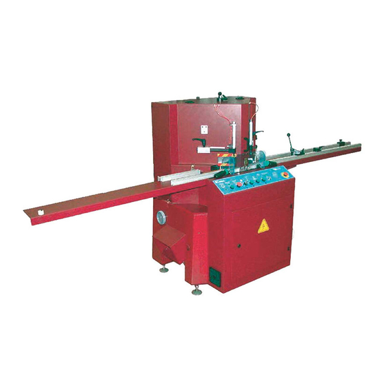
I - INTRODUCTION Saw CS 999 is a machine used to cut 45° mitres on all mouldings with solid or reconstituted wood base, and with or without coating (paint, varnish, plastic coating, paper, metal leaf such as gold, bronze, aluminium, etc.). -
Page 7: Cs 999 Overall Dimensions
STANDARD CS 999 OVERALL DIMENSIONS... -
Page 8: Unpacking And Handling
This machine is packaged in a crate containing 1 right extension arm with Slot base measuring system EXCEPT FOR NUMERIC STOP OPTION + Fixed stop + Retractable stop (Option: CS 999> S/N 68). · 1 left extension arm · 1 box containing... - Page 9 Remove the suction tip. Using a cross-head screwdriver remove the wedges from the 4 legs of the machine. Handling: Use a fork-lift truck fitted with forks at least 115 cm long, taking care to position them correctly below the frame: see below. Gross weight of machine: 770 kg. CAUTION: TO MOVE THE MACHINE FROM THE PALLET TO THE GROUND SET THE FORKS 330 MM APART.
-
Page 10: Setting Up The Machine
IV - SETTING UP THE MACHINE There must be sufficient clearance around the machine to allow free movement and access for maintenance. It must be placed on a stable and generally flat floor. Before making any electrical or pneumatic connections, level the machine by means of the adjustable feet. -
Page 11: Electrical Connections
Fitting the offcut outlet case SORTIE CHUTE Fit the offcut outlet case using screws C1 and C2 (5-mm Allen key). C1 C2 Electrical connection The user must connect the power supply cable to a source complying with the regulations in force and protect the machine by fitting fuses: 10 Amp aM for 380 Volt 3-phase and 16 Amp aM for 220 Volt 3-phase. -
Page 12: Starting Up
- Switch on the machine: main isolating switch at bottom right of the machine (see drawing on Page A). Indicator lamp V (Fig. 3, Page 6) lights up. This indicator lamp only lights if the CS 999 is MAIN ON/OFF SWITCH PRESSURE REGULATOR energised. -
Page 13: Sawing
VI - SAWING A- Adjusting the height of the blades Set key A to “blade setting”. Press D and D’ (Fig. 4, Page 6) to bring the blades to low position. Place the moulding to be cut on the cutting table. Holding rule R by its loop, release handle M located on top of the cover. -
Page 14: Measuring The First Piece
Start up the blade motors via button 2 of the control panel (Fig. 3, Page 6), then use buttons D and D’ (Fig. 4, Page 6) to actuate clamping followed by blade lowering. The first cut is then produced. Buttons D and D’ (Fig. 4, Page 6) activate a two-hand control. The time between pressing the two buttons must not exceed 0.5 seconds. -
Page 15: Retractable Stop
Allows the measuring and cutting of two dimensions of the frame, at any time. Fig A Fig B The Cassese removable stop is a positive stop, easy to retract, by a simple action on lever L. It remains stable and without play both in engaged and retracted positions. Measuring Scale Each measuring stop is indexed (red mark Il 8c I2) which indicate which one of the two scales (rules) is to be used with this stop.These scales are for direct read-off of outside measurements of... -
Page 16: Cutting The First Piece
E- Cutting the first piece The moulding is in contact with either the mobile stop or the retractable stop. Press buttons D and D’ (Fig. 4, Page 6) for left and right clamping followed by blade lowering. END OF MOULDING Clamping and cutting are visible to the operator. -
Page 17: Maintenance And Servicing
VII - MAINTENANCE AND SERVICING When the cover is open, motor start-up and blade lowering are disabled by the safety unit PROCEDURE FOR ACCESS INSIDE THE MACHINE Opening the main case - Press button 3 on the control panel (Fig. 3, Page 6) if necessary. - Position the control panel key to “unlock cover”. -
Page 18: Removing / Refitting The Blades
REMOVING THE BLADES IMPORTANT Switch off the machine at the main isolating switch (Page 6) located on the right of the machine and lock the switch by padlocking the tab. During this operation gloves should be worn to handle the blades and to avoid getting yours hands caught. -
Page 19: Replacing The Martyr Cube
REPLACING THE MARTYR CUBE Open the main case (Page 11). Loosen screw V1 using a 5-mm Allen key and remove the worn martyr cube by sliding it towards the inside of the machine. Refit the martyr cube so that a sound side is facing the blades and secure it with screw V1. Close the main case. -
Page 20: Replacing The Offcut Support Bar
REPLACING THE OFFCUT SUPPORT BAR Open the main case (see Page 11). Open the door of the electrical cabinet using the key provided and remove screws A and B. Tilt the cabinet by pulling it towards you. (Page 11). Next remove screw VTR (5-mm Allen key) and lower the setting rod of the offcut support bar. Remove screws C and D (4-mm Allen key) and remove the worn offcut support bar (AS). -
Page 21: Replacing The Table Edges
LIf the cut has defects such as tears of the paper coating (covered mouldings) or splintering of the base (below the moulding) you must REPLACE THE TABLE EDGES Open the main case (see procedure on Page 11). Switch off the machine at the main isolating switch located on the right side of the machine and lock the switch by padlocking the tab. -
Page 22: Maintenance / Troubleshooting
MAINTENANCE Depending on the frequency of use. On the basis of 8 hours work a day: Cleaning : clean the plexiglass screen with a soft cloth Belt inspection : every 3 months Blade sharpening : good cutting is the result of good sharpening We recommend contacting your dealer for this service. -
Page 23: List Of Wearing Parts
FAULT POSSIBLE CAUSES Indicator lamp V1 is off. Safety chain broken. Open the electrical cabinet and check on the electronic card to see which item in the chain is faulty (LED red lit). THERMAL CIRCUIT BREAKER 1 COVER SAFETY DEVICE THERMAL CIRCUIT BREAKER 2 Reset the thermal safety device.
Need help?
Do you have a question about the CS 999 and is the answer not in the manual?
Questions and answers