
Subscribe to Our Youtube Channel
Related Manuals for Cassese CS 960


Summary of Contents for Cassese CS 960
-
Page 1: Instructions For Use
Z15768 CS 960 Manual Operated Double-Mitre Saw 45° Instructions for Use & Technical Data VERSION 2 - 09-2005 Cassese Communication... -
Page 2: Cs 960 Description
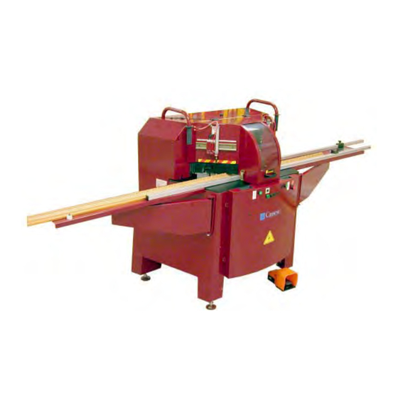
CS 960 DESCRIPTION Blade carriage arms Left vertical clamp Main case handle Moulding guide Left vertical clamp (option) Left horizontal clamp handle Right table Left horizontal clamp Main case handle Left table Right vertical clamp (option) Right vertical clamp handle... -
Page 3: Technical Data
TECHNICAL DATA CS 960 PRODUCT NAME Year of creation 2005 Cutting capacity: maximum width 160 mm maximum moulding height 110 mm Blade dimensions 350 mm Ø Bore 30 mm Ø Maximium cutting length: 1500 mm Rotation speed: 2800 rpm (... -
Page 5: Table Of Contents
Contents CS 960 DESCRIPTION TECHNICAL DATA CS 960 OVERALL DIMENSIONS - INTRODUCTION - UNPACKING & HANDLING 2, 3 III - SETTING UP THE MACHINE - Installing the right and left tables - Electrical connections - Air connections - Dust extraction... -
Page 6: I- Introduction
INTRODUCTION The CS 960 saw is used to produce 45° mitre cuts on all mouldings made from solid or reconstituted wood, with or without coating (paint, varnish, plastic, paper, metal leaf such as gold, bronze, aluminium, etc.). It cannot be used for: ·... -
Page 7: Unpacking & Handling
II - UNPACKING AND HANDLING This machine is packed in a crate containing: · 1 right table extension with Slot base measuring system + Fixed stop · 1 left table extension · 1 box containing: - 1 Allen key, 10 mm (blade removal) - 1 Allen key, 4 mm (table assembly) - 1 Allen key, 2,5 mm + 1 Allen key, 5 mm + 1 Allen key, 6 mm - 1 quick-fit connector (fitted on machine) / 1 barbed connector / 1 USA connector / 1 quick-fit coupling (see page 6) / 1 blade steadying handle... - Page 8 CAUTION: SETTING THE FORK SPACING MOVING THE PALLET TO THE FLOOR: FRONT PANEL = 670 MM - SIDE: 530 MM THEN SET THE FORK SPACING FOR THE REMAINING MOVEMENT (SEE DRAWING BELOW). POSITION OF THE FORKS: EQUIDISTANT FROM THE FRAME AXIS. Manutention par la face avant / Handling from the front Manutención por la cara anterior CAUTION:...
-
Page 9: Iii - Setting Up The Machine
There must be sufficient clearance around the machine to allow free movement and access for maintenance (see page C). The CS 960 must be installed on a stable, flat floor capable of supporting its weight (950 kg). Before making any electrical and pneumatic connections, level the machine by means of the adjustable feet. - Page 10 Using a 4-mm Allen key, slightly loosen the locking screws on stops BD and BG located beolw each table extension. This allows stops BD and BG to slide along them. Do not loosen the screws of the internal measuring stop BMI (factory setting). D’...
-
Page 11: Electrical Connections
- Switch on the machine: main isolating switch at top right of the machine (see CS 960 description page A). Indicator lamp 3 (see Control panel, page 7) lights. This indicator only lights when the CS 960 is energised. MAIN ISOLATING SWITCH PRESSURE Unlock button 5 then press button 4 (see Control panel, page 7). -
Page 12: Control Panel
FITTING THE LEFT AND RIGHT ARMS OF THE CARRIAGE Open the removable panel at the rear of the machine, after unscrewing the 4 screws (5-mm Allen key). Fix the left arm to the blade carriage using screws V1 and V2 (6-mm Allen key). Repeat the operation for the right arm. -
Page 13: Vertical Clamp Setting
SETTING THE VERTICAL CLAMPS (OPTION) MEASURE MEASURE RIGHT VERTICAL CLAMP LEFT VERTICAL CLAMP After releasing the handle (M2), position the vertical clamp positioning arms (BP) according to the profile and the width of the moulding. Apply the clamps by lifting your foot from the pedal, checking that the clamp pressor does not tilt the moulding. -
Page 14: Measuring The First Piece
MEASURING THE FIRST PIECE (MOBILE STOP) MEASURING THE SLOT BASE (INSIDE MEASUREMENT) RULE LOCKING SCREW 45° READING POINT Slide the CURSOR along the rule and lock it at the required dimension by tightening its locking screw. Press the pedal to release the clamps. Move the moulding to the cursor aligning the edge of the slot base with the 45°... -
Page 15: Cutting The First Piece
CUTTING THE FIRST PIECE The moulding is in contact with the mobile stop. - Unlock button 5. - Lift your foot from the pedal (clamping position). - Press button 4 on the control panel (to start the blade). - Press button 1 continuously with a finger of the left hand. This releases the right blade. - Grip the arm of the right blade carriage with your right hand and pull it slowly towards the clamped profile. -
Page 16: Opening The Main Case
VI - MAINTENANCE REMOVING THE BLADES IMPORTANT Disconnect the air supply. Switch off the machine at the main isolating switch on the right of the machine and lock it by installing a padlock on the tab. During this operation, gloves should be worn to handle the blades and avoid getting your hands caught. -
Page 17: Replacing The Martyr Cube
REPLACING THE MARTYR CUBE Open the main case (see page 11). Unscrew screw V1 using a 2-mm Allen key and remove the worn martyr block by pulling it upwards. Turn the martyr cube over through 180°, refit it in its housing and secure it by retightening screw V1.
Need help?
Do you have a question about the CS 960 and is the answer not in the manual?
Questions and answers