Advertisement
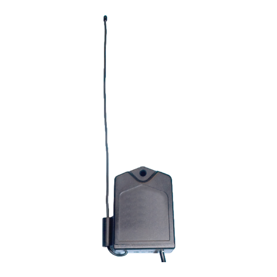
RB709U-NB
Relay Output Universal Receiver
Owner's Manual
Designed to work with most brands of gate and
door openers.
The RB709U-NB digital receiver is a
wireless radio control designed for
use with automated gate openers and
garage door openers. The receiver
has two channels for receiving sig-
nals from two activation devices; i.e.
transmitters, multi-button transmitters,
wireless keypads, etc.
Printed in China for GTO - Gates That Open, LLC rev-090810
Mounting the Receiver
Consider the following when mounting the receiver:
• Standard receiver cable length is 10 feet (3.05 m).
• For exterior applications run the cable through
PVC conduit to protect it from damage.
• DO NOT run cable in conduit containing ac wiring.
• The receiver range can vary from 50 to 100
feet (15.2 to 30.5 m) depending upon weather,
topography, and external interference.
NOTE: Do not mount upside down.
Compatible transmitter:
Power input:
Outputs: 2 channels pulsed outputs
Indoor/Outdoor compatible.
Mount receiver at least 3 feet from AC power source.
www.gtoaccess.com
Specifications
• GTO gray narrow band transmitters (318MHz)
• 8-24 V ac/dc, 10ma standby, 40ma activated (Red & Black wires).
• 2 channels dry-contact normally open relay outputs.
• Channel 1: Blue (N/O Contact) & Green (COM) wires.
• Channel 2: Yellow (N/O Contact) & Brown (COM) wires.
• Activated for .5 seconds when the correct transmitter code is received.
• Relay switching maximum rating: 24Vac/dc @ 1A.
• Operating Range 50 to 100 feet (15.2 to 30.5 m)
FCC Regulation
This device complies with FCC rules Part 15. Operation is subject to the following conditions:
1. This device may not cause harmful interference.
2. This device must accept an interference that may cause undesired operation.
Transmitter distance may vary due to circumstances beyond our control. NOTE: The manufacturer
is not responsible for any radio or TV interference caused by unauthorized modifications to this
equipment. Such modifications could void the user's authority to operate the equipment.
Connect Receiver to Relay Inputs and Power
8 to 24 VOLT AC/DC
RED
POWER SUPPLY
BLACK
RED WIRE to POSITIVE
BLACK WIRE to NEGATIVE
GREEN
BROWN
YELLOW
1st GATE OPERATOR or DOOR OPENER
Channel 1 (To COM)
BLUE
Channel 1 (To N/O Contact)
Channel 2 (To COM)
Channel 2 (To N/O Contact)
2nd GATE OPERATOR or DOOR OPENER
Advertisement
Table of Contents

Related Manuals for GTO RB709U-NB


Summary of Contents for GTO RB709U-NB
- Page 1 TV interference caused by unauthorized modifications to this equipment. Such modifications could void the user’s authority to operate the equipment. www.gtoaccess.com Printed in China for GTO - Gates That Open, LLC rev-090810 Mounting the Receiver Connect Receiver to Relay Inputs and Power Consider the following when mounting the receiver: • Standard receiver cable length is 10 feet (3.05 m).
- Page 2 Programming the Receiver Wiring Receiver to GTO GP-SL100 & GP-SW100 Operators Programming transmitter(s) or other access devices to RB709U-NB receiver: • Press and hold the transmitter (device) button to be learned. GTO GP-SL100 and GP-SW100 Contol Board • Press the ‘LEARN CH1’ (or ‘LEARN CH2’) button on the RB709U-NB receiver for 1-2 seconds or until the red LED turns on, then release the button. • Note: When the correct code is received and the corresponding relay output is activated, the red LED will turn on. ACC. POWER DUAL CABLE RELAY OUTPUTS Channel 2 (YELLOW WIRE to N/O Contact) Check operation after programming: Channel 2 (BROWN WIRE to COM) • Press Transmitter (device) button, #1 - RED LED blinks once to confirm.
Need help?
Do you have a question about the RB709U-NB and is the answer not in the manual?
Questions and answers