
Related Manuals for Vip-Vision INTIPMONDW


Summary of Contents for Vip-Vision INTIPMONDW
- Page 1 VIP Residential IP Intercom Installation Guide INTIPMOND(W/B) / INTIPRDSDB / INTIPRDSVW VIP Vision Residential IP Intercom Installation Guide - v1.3 Issued April 2017...
-
Page 2: Table Of Contents
P2P Configuration (QR Code) 3.13 Advanced Configuration for Remote Access (optional) 3.14 Changing Door Station Network Ports (optional) 3.15 Finding out your network range, and available IP addresses via PC VIP Vision Residential IP Intercom Installation Guide - v1.3 Issued April 2017... - Page 3 Taking Videos / Snapshots from the Indoor Monitor Viewing Your Videos/Snapshots from the Indoor Monitor Viewing Your Videos/Snapshots from a Computer Calling Between Indoor Monitors Create Favourites Updating Intercom Firmware Troubleshooting Limited Warranty VIP Vision Residential IP Intercom Installation Guide - v1.3 Issued April 2017...
-
Page 4: Pre-Installation
IP Address in to the address bar. e.g. http://192.168.1.110 (Refer to Section 3.1 for how to change the door station's IP address.) 2. Log in with the default username admin, password also admin. VIP Vision Residential IP Intercom Installation Guide - v1.3 Issued April 2017... -
Page 5: Components
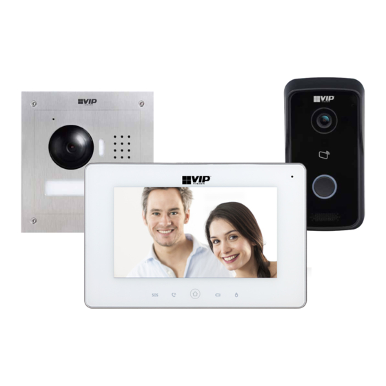
• Loudspeaker • Door Release Output VIP Residential IP Intercom Door Station Product ID — INTIPRDSVW • 1MP Camera • IP54 Rated • Loudspeaker • Door Release Output VIP Vision Residential IP Intercom Installation Guide - v1.3 Issued April 2017... - Page 6 Connect a Cat5 cable with the included adaptor Debug port Unused RS485 485 expansion interface Alarm interface 6ch alarm input / 1ch alarm output Speaker Audio output SD card slot For external SD storage VIP Vision Residential IP Intercom Installation Guide - v1.3 Issued April 2017...
- Page 7 Reset button Resets the Door Station RJ-45 port Connect a Cat5 cable with the included adaptor Input connectors Connections for 12V DC and Door Strike wiring VIP Vision Residential IP Intercom Installation Guide - v1.3 Issued April 2017...
- Page 8 RJ-45 Port Connect a Cat5 cable with the included adaptor Debug Port Unused Input Connectors Connections for 12V DC and Door Strike wiring VIP Vision Residential IP Intercom Installation Guide - v1.3 Issued April 2017...
-
Page 9: Installation
Install each unit at their respective location and connect the devices together with a Cat5 cable. Power both the Indoor Monitor and Door station with 12VDC. You have now successfully connected your VIP Residential IP Intercom. VIP Vision Residential IP Intercom Installation Guide - v1.3 Issued April 2017... -
Page 10: Indoor Monitor To 1 Door Station Via A Network Switch (Hardwired)
IP addresses to both the Door Station and Indoor Monitor. Device IP Adresses Subnet Mask Gateway Room Number VTO Number Door Station 10.1.1.110 255.255.255.0 10.1.1.1 6901 Master Indoor 10.1.1.111 255.255.255.0 10.1.1.1 9901 Monitor VIP Vision Residential IP Intercom Installation Guide - v1.3 Issued April 2017... -
Page 11: Door Station Configuration
Turn off power to both the Door Station and Indoor Monitor, after 10 seconds, turn the power back on. You have now successfully connected your VIP Residential IP Intercom. VIP Vision Residential IP Intercom Installation Guide - v1.3 Issued April 2017... -
Page 12: Indoor Monitor To 1 Door Station Via A Wireless Access Point (Wireless)
IP addresses to both the Door Station and Indoor Monitor. Device IP Adresses Subnet Mask Gateway Room Number VTO Number Door Station 10.1.1.110 255.255.255.0 10.1.1.1 6901 Master Indoor 10.1.1.111 255.255.255.0 10.1.1.1 9901 Monitor VIP Vision Residential IP Intercom Installation Guide - v1.3 Issued April 2017... -
Page 13: Door Station Configuration
In this example, we are going to change the IP address of the Door Station to 10.1.1.110, the Subnet Mask to 255.255.255.0 and the Default Gateway to 10.1.1.1. VIP Vision Residential IP Intercom Installation Guide - v1.3 Issued April 2017... -
Page 14: Indoor Monitor Configuration
“MyAP”. When prompted, enter the password for the Access Point, then select “OK”. After 30 seconds, your Door Station will connect to the Access Point. VIP Vision Residential IP Intercom Installation Guide - v1.3 Issued April 2017... - Page 15 Turn off power to both the Door Station and Indoor Monitor, after 10 seconds, turn the power back on. You have now successfully connected your VIP Residential IP Intercom. VIP Vision Residential IP Intercom Installation Guide - v1.3 Issued April 2017...
-
Page 16: Indoor Monitors To 1 Door Stations Via Wireless Access Point (Wireless)
IP Adresses Subnet Mask Gateway Room Number VTO Number Door Station 10.1.1.110 255.255.255.0 10.1.1.1 6901 Master Indoor 10.1.1.111 255.255.255.0 10.1.1.1 9901 Monitor Extension 10.1.1.113 255.255.255.0 10.1.1.1 9901-1 Indoor Monitor VIP Vision Residential IP Intercom Installation Guide - v1.3 Issued April 2017... -
Page 17: Door Station Configuration
In this example, we are going to change the IP address of the Door Station to 10.1.1.110, the Subnet Mask to 255.255.255.0 and the Default Gateway to 10.1.1.1. VIP Vision Residential IP Intercom Installation Guide - v1.3 Issued April 2017... -
Page 18: Master Indoor Monitor Configuration
“MyAP” When prompted, enter the password for the Access Point, then select “OK”. After 30 seconds, your Door Station will connect to the Access Point. VIP Vision Residential IP Intercom Installation Guide - v1.3 Issued April 2017... -
Page 19: Extension Indoor Monitor Configuration
On the “Extension” Indoor Monitor, press and hold the “Settings” button for 6 seconds, then enter the password (888888 by default). Select “WLAN", then select “ON”. Select “Wireless IP” and set “DHCP” to “ON”, then select “OK”. VIP Vision Residential IP Intercom Installation Guide - v1.3 Issued April 2017... - Page 20 Enter the IP address of the “Master” Indoor Monitor and press “OK” to save. In this example, we are going to change the IP address of the Master Indoor Monitor to 10.1.1.111 VIP Vision Residential IP Intercom Installation Guide - v1.3 Issued April 2017...
- Page 21 Turn off power to each Door Station and Indoor Monitor, after 10 seconds, turn the power back on. You have now successfully connected your VIP Residential IP Intercom VIP Vision Residential IP Intercom Installation Guide - v1.3 Issued April 2017...
-
Page 22: Indoor Monitors To 1 Door Station Via A Network Switch (Hardwired)
IP Adresses Subnet Mask Gateway Room Number VTO Number Door Station 10.1.1.110 255.255.255.0 10.1.1.1 6901 Master Indoor 10.1.1.111 255.255.255.0 10.1.1.1 9901 Monitor Extension 10.1.1.113 255.255.255.0 10.1.1.1 9901-1 Indoor Monitor VIP Vision Residential IP Intercom Installation Guide - v1.3 Issued April 2017... -
Page 23: Door Station Configuration
In this example, we are going to change the IP address of the Indoor Monitor to 10.1.1.111 the Subnet Mask to 255.255.255.0 and the Default Gateway to 10.1.1.1. VIP Vision Residential IP Intercom Installation Guide - v1.3 Issued April 2017... -
Page 24: Extension Indoor Monitor Configuration
Indoor Monitor but add “ -1 “ to show that it is the first extension (such as 9901-1). Enter the IP address of the “Master” Indoor Monitor 10.1.1.112 and press “OK” to save. VIP Vision Residential IP Intercom Installation Guide - v1.3 Issued April 2017... - Page 25 Turn off power to each Door Station and Indoor Monitor, after 10 seconds, turn the power back on. You have now successfully connected your VIP Residential IP Intercom. VIP Vision Residential IP Intercom Installation Guide - v1.3 Issued April 2017...
-
Page 26: Indoor Monitors To 2 Door Stations Via A Wireless Access Point (Wireless)
Door Station 1 10.1.1.110 255.255.255.0 10.1.1.1 6901 Door Station 2 6902 10.1.1.111 255.255.255.0 10.1.1.1 Master Indoor 10.1.1.112 255.255.255.0 10.1.1.1 9901 Monitor Extension 10.1.1.113 255.255.255.0 10.1.1.1 9901-1 Indoor Monitor VIP Vision Residential IP Intercom Installation Guide - v1.3 Issued April 2017... -
Page 27: Door Station 1 Configuration
In this example, we are going to change the IP address of the Door Station to 10.1.1.110, the Subnet Mask to 255.255.255.0 and the Default Gateway to 10.1.1.1. VIP Vision Residential IP Intercom Installation Guide - v1.3 Issued April 2017... -
Page 28: Door Station 2 Configuration
In this example, we are going to change the IP address of the Door Station to 10.1.1.111, the Subnet Mask to 255.255.255.0 and the Default Gateway to 10.1.1.1. VIP Vision Residential IP Intercom Installation Guide - v1.3 Issued April 2017... -
Page 29: Master Indoor Monitor Configuration
Point you wish to connect to. In this example, we are going to connect to “MyAP” When prompted, enter the password for the Access Point, then select “OK”. VIP Vision Residential IP Intercom Installation Guide - v1.3 Issued April 2017... - Page 30 IP address that was set on the second Door Station, in this example the IP address is 10.1.1.111. Ensure “Enable Status” is set to “ON” for both the Main and Sub VTO. VIP Vision Residential IP Intercom Installation Guide - v1.3 Issued April 2017...
-
Page 31: Extension Indoor Monitor Configuration
“MyAP” When prompted, enter the password for the Access Point, then select “OK”. After 30 seconds, your Door Station will connect to the Access Point. VIP Vision Residential IP Intercom Installation Guide - v1.3 Issued April 2017... - Page 32 Turn off power to each Door Station and Indoor Monitor, after 10 seconds, turn the power back on. You have now successfully connected your VIP Residential IP Intercom. VIP Vision Residential IP Intercom Installation Guide - v1.3 Issued April 2017...
-
Page 33: Indoor Monitors To 2 Door Stations Via A Network Switch (Hardwired)
Door Station 1 10.1.1.110 255.255.255.0 10.1.1.1 6901 Door Station 2 6902 10.1.1.111 255.255.255.0 10.1.1.1 Master Indoor 10.1.1.112 255.255.255.0 10.1.1.1 9901 Monitor Extension 10.1.1.113 255.255.255.0 10.1.1.1 9901-1 Indoor Monitor VIP Vision Residential IP Intercom Installation Guide - v1.3 Issued April 2017... -
Page 34: Door Station 1 Configuration
(for example, 6901 for the first Door Station and 6902 for the second Door Station). Press “OK”. Repeat this set for each additional Door Station. VIP Vision Residential IP Intercom Installation Guide - v1.3 Issued April 2017... -
Page 35: Master Indoor Monitor Configuration
IP address that was set on the second Door Station, in this example the IP address is 10.1.1.111. Ensure “Enable Status” is set to “ON” for both the “Main” and “Sub” VTO. VIP Vision Residential IP Intercom Installation Guide - v1.3 Issued April 2017... -
Page 36: Extension Indoor Monitor Configuration
Turn off power to both the Door Station and Indoor Monitor, after 10 seconds, turn the power back on. You have now successfully connected your VIP Residential IP Intercom. VIP Vision Residential IP Intercom Installation Guide - v1.3 Issued April 2017... -
Page 37: Additional Configuration
9901-1 for your first Extension monitor, and 9901-2 for the second. 5. Enter the IP Address of your Master monitor e.g. 10.1.1.112. Press “OK” to save. VIP Vision Residential IP Intercom Installation Guide - v1.3 Issued April 2017... -
Page 38: Setting The Time And Date
2. On the Indoor Monitor go to “Settings” > “Ring”. In this menu you can adjust ring tones and volume levels. 3. After you have made your changes, select “OK”. VIP Vision Residential IP Intercom Installation Guide - v1.3 Issued April 2017... -
Page 39: Door Station Volume Configuration
(Refer to Section 1.2 for how to log in.) 2. Once logged in, go to “System Config” > “Video Set”. In this menu you can change the Door Station’s video settings. VIP Vision Residential IP Intercom Installation Guide - v1.3 Issued April 2017... -
Page 40: Wiring An Electric Door Strike To The Door Station
If you wish to wire in an external button to trigger the door latch, connect the button to the terminals marked “Unlock” and “GND”. 485-B 485-A Lock — UNLOCK FEEDBACK VIP Vision Residential IP Intercom Installation Guide - v1.3 Issued April 2017... -
Page 41: Adjust Electric Door Strike Timing
Select “OK’ . 6. Repeat steps 4-5 to learn in additional cards. 7. Select “Confirm Issue”. 8. Your swipe cards are now learnt into the Door Station. VIP Vision Residential IP Intercom Installation Guide - v1.3 Issued April 2017... -
Page 42: Deleting Swipe Cards
1. On the Indoor Monitor, press and hold the “Settings” button for 6 seconds, then enter the password for the Network Settings (888888 by default). Select “VTH Set” Turn the “Unlock” option, to “OFF”. VIP Vision Residential IP Intercom Installation Guide - v1.3 Issued April 2017... -
Page 43: P2P Configuration (Qr Code)
4. After waiting 2 minutes, press the refresh button, the “Status” should display “Online”. 5. Open the mobile application. 6. On the mobile application go to “MENU” then “Home”. 7. Select “Door”. 8. Select “Device Manager". VIP Vision Residential IP Intercom Installation Guide - v1.3 Issued April 2017... - Page 44 You have now successfully connected your VIP Residential IP Intercom for remote access. In the future, you can connect to your system directly from the main screen by tapping the Device Manager button, then selecting your intercom. VIP Vision Residential IP Intercom Installation Guide - v1.3 Issued April 2017...
-
Page 45: Advanced Configuration For Remote Access (Optional)
3. In this menu, you can modify the ports to suit your requirements. Press “OK” to save the settings. 4. Select “Logout” > “Reboot”. The Door Station will now restart with the changes you have made. VIP Vision Residential IP Intercom Installation Guide - v1.3 Issued April 2017... -
Page 46: Finding Out Your Network Range, And Available Ip Addresses Via Pc
Mask and Default Gateway, as recorded in step 4. Eg: IP Address – 192.168.0.50 Subnet mask – 255.255.255.0 Default Gateway – 192.168.0.1 9. If you require additional IP addresses, follow steps 5 through 7. VIP Vision Residential IP Intercom Installation Guide - v1.3 Issued April 2017... -
Page 47: Using A Poe Switch To Power The Intercom System (Sold Separately)
Door Station. One PoE receiver is required for each device you wish to power. Note that the INTIPRDSDB, INTIPMONDW and INTIPMONDB have PoE compatibility, and do not require a PoE Receiver. VIP Vision Residential IP Intercom Installation Guide - v1.3 Issued April 2017... -
Page 48: Adding Ip Cameras To An Indoor Monitor
To view the camera, select “Monitor” > “IPC”, then select the camera you wish to view. To view a camera when a call is incoming, you can select the camera icon on the bottom of the screen, then select the camera you wish to view. VIP Vision Residential IP Intercom Installation Guide - v1.3 Issued April 2017... -
Page 49: Adding Your Door Station To A Vip Vision Nvr
Adding Your Door Station to a VIP Vision NVR If you have a VIP Vision NVR, you can add your Door Station as a camera. To do this both your NVR, and intercom Door Station must be on the same IP address range. -
Page 50: How To Use Your Intercom System
Viewing Your Videos/Snapshots from the Indoor Monitor To view recorded videos on the Indoor Monitor, select “Info” then “Guest Message”. To view snapshots on the Indoor Monitor, select “Info” then “Video Pictures”. VIP Vision Residential IP Intercom Installation Guide - v1.3 Issued April 2017... -
Page 51: Viewing Your Videos/Snapshots From A Computer
If you are calling from the “Master” monitor to an “Extension” monitor, enter “-1”. If you are calling from an “Extension” monitor to the “Master” monitor, enter the room number, e.g. 9901. VIP Vision Residential IP Intercom Installation Guide - v1.3 Issued April 2017... -
Page 52: Create Favourites
9901, then press the “OK” button. 3. The device will now be added to the favourites list. Select the name and then press the “Call” button. VIP Vision Residential IP Intercom Installation Guide - v1.3 Issued April 2017... -
Page 53: Updating Intercom Firmware
Updating Intercom Firmware The below instructions cover how to update firmware on the VIP Vision Intercom Door Station and Indoor Monitor. Before starting, you must obtain the most recent firmware version for your intercom products. 1. Download the Config Tool from the Support page on the VIP Vision website (www.vip-vision.com). - Page 54 After upgrading the firmware, if you are unable to login to the Door Station and are presented with a corrupt login screen, please clear you Internet Explorer Browser History. VIP Vision Residential IP Intercom Installation Guide - v1.3 Issued April 2017...
-
Page 55: Troubleshooting
P2P Connection Status is “Offline” • Ensure that the IP address, subnet mask and default gateway of the Door Station is in the same IP address range as the existing computer network VIP Vision Residential IP Intercom Installation Guide - v1.3 Issued April 2017... -
Page 56: Limited Warranty
No increase or alteration, written or verbal, of the obligations of this Limited Warranty is authorized. Please refer to the website (www.vip-vision.com) for a full list of trading terms. VIP Vision Residential IP Intercom Installation Guide - v1.3 Issued April 2017...
Need help?
Do you have a question about the INTIPMONDW and is the answer not in the manual?
Questions and answers