Advertisement
Quick Links
VP3000*-TFJ0003
Installation and Maintenance Manual
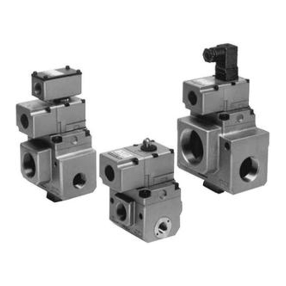
VP3145/VP3165/VP3185, Large Size 3 Port Solenoid Valve, Rubber Seal
VP3145/VP3165/VP3185-X80/X81, Main Valve Double Acting Type
X
Read this manual before using this product
The information within this document is to be used by pneumatically trained
personnel only.
For future reference, please keep manual in a safe place.
This manual should be read in conjunction with the current catalogue.
1 SAFETY
1.1 General recommendation
These safety instructions are intended to prevent a hazardous situation and/or
equipment damage. These instructions indicate the level of potential hazard by label of
"Caution", "Warning" or "Danger". To ensure safety, be sure to observe ISO4414
JIS B 8370
(Note2)
and other safety practices.
Note 1:ISO 4414:Pneumatic fluid power - General rules relating to systems.
Note 2:JIS B 8370:Pneumatic system axiom.
CAUTION:
Operator error could result in injury or equipment damage.
WARNING:
Operator error could result in serious injury or loss of life.
DANGER:
In extreme conditions, there is a possible result of serious
injury or loss of life.
WARNING:
• The compatibility of pneumatic equipment is the responsibility of the
person who designs the pneumatic system or decides its specifications.
Since the products specified here are used in various operating conditions, their
compatibility for the specific pneumatic system must be based on specifications
or after analysis and/or tests to meet your specific requirements.
• Only trained personnel should operate pneumatically operated machinery
and equipment.
Compressed air can be dangerous if an operator is unfamiliar with it Assembly,
handling or repair of pneumatic systems should be performed by trained and
experienced operators.
• Do not service machinery/equipment or attempt to remove components
until safety is confirmed.
Inspection and maintenance of machinery/equipment should only be performed
after confirmation of safe locked-out control positions.
When equipment is to be removed, confirm the safety process as mentioned
above. Switch off air and electrical supplies and exhaust all residual compressed
air in the system.
Before machinery/equipment is re-started, ensure all safety measures to prevent
sudden movement of cylinders etc. (Bleed air into the system gradually to create
backpressure, i.e. incorporate a soft-start valve).
• Contact SMC if the product is to be used in any of the following conditions:
Conditions and environments beyond the given specifications, or if product is
used outdoors.
Installations on equipment in conjunction with atomic energy, railway, air
navigation, vehicles, medical equipment, food and beverage, recreation
equipment, emergency stop circuits, press applications, or safety equipment.
An application, which has the possibility of having negative effects on people,
property, or animals, requiring special safety analysis.
CAUTION:
Ensure that the air supply system is filtered to 5 micron.
1.2 Conformity to standard
This product is certified to and complies with the following standards:
EMC Directive 89/336/EEC
EN50082-2, EN55011
Low voltage directive 93/68/EEC
DIN VDE 0580
2 INTENDED CONDITIONS OF USE
2.1 Specifications
VP3145/3165/3185 Specifications
(Note 1)
IBased on dynamic performance test, JIS B 8374-1981. (Coil temperature:
20°C, at rated voltage, without surge voltage suppressor)
(Note1)
,
(Note 2)
This solenoid valve requires lubrication. Use turbine oil Class 1 (ISO VG32).
(Note 3)
Impact resistance:
No malfunction occurred when it is tested with a
drop tester in the axial
direction and at the right angles to the main valve
and armature in both
energized and de-energized states every once for
each condition. (Values
at the initial period)
Vibration resistance:
No malfunction occurred in a one-sweep test
between 45 and 1000 Hz. Test was performed at
both energized and de-energized states in the axial
direction and at the right angles to the main valve
and armature. (Values at the initial period)
VP3145/3165/3185-X80/X81 Specifications
(Note 1)
This solenoid valve requires lubrication. Use turbine oil Class 1 (ISO VG32).
(Note 2)
Impact resistance:
No malfunction occurred when it is tested with a
drop tester in the axial direction and at the right
angles to the main valve and armature in both e
energized and de-energized states every once for
each condition. (Values at the initial period)
Vibration resistance:
No malfunction occurred in a one-sweep test
between 45 and 1000 Hz. Test was performed at
both energized and de-energized states in the axial
direction and at the right angles to the main valve
and armature. (Values at the initial period)
2.2 External Pilot
Please use external pilot type in the following cases.
In vacuum, or low pressure of 0.2MPA or under: External pilot type for
vacuum/low pressure
In cases where the IN port will be extremely constricted: External pilot type for
general use
In cases where startup of the IN port side pressure is slow (takes a long time for
pressure to be established).: External pilot type for general use
In cases where the secondary side piping resistance is small, for example where
it is used for blow-off or tank filling etc.: External pilot type for general use
Note 1. Please use with external pilot pressure within the range shown by the
diagram below.
Note 2. It is not possible to recombine an external pilot type in place of an internal
pilot type, or vice versa.
2.3 Piping
2.3 Circuit Symbols
3 INSTALLATION
WARNING:
Do not install unless the safety instructions have been read and understood.
3.1 Environment
WARNING:
Do not use in an environment where the product is directly exposed to corrosive
gases, chemicals, salt water, water or steam.
Do not use in an explosive atmosphere.
The product should not be exposed to prolonged sunlight. Use a protective cover.
Do not mount the product in a location where it is subject to strong vibrations
and/or shock. Check the product specifications for above ratings.
Do not mount the product in a location where it is exposed to radiant heat.
3.2 Piping
CAUTION:
Before piping make sure to clean up chips, cutting oil, dust etc.
When installing piping or fitting into a port, ensure that sealant material does not
enter the port inside. When using seal tape, leave 1.5 to 2 threads exposed on the
end of pipe/fitting.
Thread
Appropriate tightening torque (Nm)
Rc 1/8
7 to 9
Rc ¼
12 to 14
RC 3/8
22 to 24
RC ½
28 to 30
RC ¾
28 to 30
RC 1
36 to 38
RC 1 ¼
40 to 42
RC 1 ½
48 to 50
Rc 2
48 to 50
3.3 Electrical connection
CAUTION:
When DC power is connected to a solenoid valve equipped with light and/or surge
voltage suppressor, check for polarity indications.
For polarity indications:
o
No diode to protect polarity: if polarity connection is wrong, the diode in the
valve or switching device at control equipment or power supply may
be damaged.
o
With diode to protect polarity: if polarity connection is wrong, the valve does
not switch.
How to use DIN terminal
1. Disassembly
1.
After loosening the thread (1), then if the cover (4) is pulled in the direction
of the thread, the connector will be removed from the body of equipment
(solenoid, etc.).
2.
Pull out the screw (1), then remove the gasket (2a) or (2b).
3.
On the bottom part of the terminal block (3), there's a cut-off part (indication
of an arrow) (3a). If a small flat head screwdriver is inserted between the
opening in the bottom, terminal block (3) will be removed from the cover (4).
(Refer to the figure below.)
4.
Remove the cable gland (5) and plain washer (6) and rubber seal (7) .
2. Wiring
1.
Pass them through the cable (8) in the order of cable ground (5), washer (6),
rubber seal (7), and then insert into the housing (4).
2.
Dimensions of the cable (8) are the figure as below. Skin the cable and crimp
the crimped terminal (9) to the edges.
3.
Remove the screw with washer (3e) from the bracket (3e). (Loosen in the case of
Y-shape type terminal.) As shown in the below figure, mount a
crimped terminal (9), and then again tighten the screw (3e).
Note) Tighten within the tightening torque of 0.5 N·m±15%.
A
It is possible to wire even in the state of bare wire. In that case, loosen the
screw with washer (3e) and place a lead wire (3d) into the bracket, and
then tighten it once again.
B
Maximum size of crimped terminal (9) is up to 1.25 mm2 -3.5 when O terminal.
For Y terminal, it is up to 1.25 mm2 -4.
C
Cable (8) external: ø6 to ø12 mm
Note) For the one with the external dimension ranged between 9 to 12mmø, remove the
inside parts of the rubber seal (7) before using.
3. Assembly
1.
Terminal block (3) connected with housing (4) should be reinstated. (Push it
down until you hear the click sound.)
2.
Putting rubber seal (7), plain washer (6), in this order into the cable
introducing slit on the housing (4), then further tighten the cable gland
(5) securely.
3.
By inserting gasket (2a) or (2b) between the bottom part of the terminal
block (3) and a plug on an equipment, screw in (1) on top of the housing
(4) and tighten it.
Note)
Tighten within the tightening torque of 0.5 N·m ±20%.
A
The orientation of a connector can be changed arbitrarily, depending on the
combination of a housing (4) and a terminal block (3).
Advertisement

Related Manuals for SMC Networks VP3145


Summary of Contents for SMC Networks VP3145
- Page 1 No diode to protect polarity: if polarity connection is wrong, the diode in the valve or switching device at control equipment or power supply may VP3145/VP3165/VP3185, Large Size 3 Port Solenoid Valve, Rubber Seal be damaged. VP3145/VP3165/VP3185-X80/X81, Main Valve Double Acting Type With diode to protect polarity: if polarity connection is wrong, the valve does not switch.
- Page 2 VP3000*-TFJ0003 3.4 Mounting LIMITATIONS OF USE If air leakage increases or equipment does not operate properly, stop operation WARNING: After mounting or maintenance, etc., connect the compressed air and power sup plies, and perform appropriate function and leakage inspections to confirm that the unit is mounted properly.