
Related Manuals for JBL BP600.1


Summary of Contents for JBL BP600.1
- Page 1 BP600.1 1 CHANNEL POWER AMPLIFIER SERVICE MANUAL JBL Consumer Products 250 Crossways Park Dr. Woodbury, New York 11797 Rev0 8/2004...
-
Page 2: Table Of Contents
Depth ......2 11/16 (68mm) JBL continually strives to improve its products. New materials, production methods and design refinements are introduced into existing models without notice as a routine expression of our design philosophy. For this reason, BP Series Automotive Amplifiers may differ in some respects from their published specifications and descriptions, but will always equal or exceed the original specifications unless otherwise stated. -
Page 3: Features
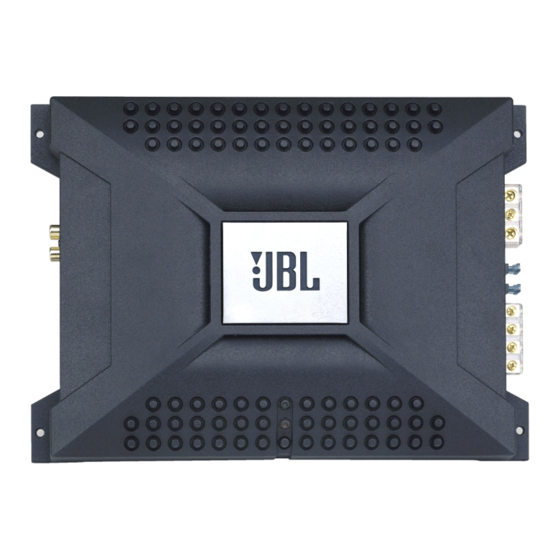
1 Channel Automotive Amplifier BP-600.1 Features 1-Channel Operation Advanced MOSFET Oversized Floating Rail Power Supply Floating Ground Factory - Head - Unit Speaker - Level input Variable Input Sensitivity (250mV - 4V) Fully Complementary Output Stage with Class-A Voltage Amplification Gold-plated Power, Input and Output Connectors 2-Ohm Stable Test Conditions and Notes... -
Page 4: Controls And Connections
Mounting the Amplifier The JBL BP Series amplifiers can be mounted in virtually any location inside the vehicle. However, make sure to keep the amplifier away from heater vents or ducts. 1. At the chosen site, use the amplifier as a mounting template and mark the locations of the four mounting holes. -
Page 5: Typical System Configuration (Wiring)
1 Channel Automotive Amplifier BP-600.1 Typical System Configuration Cassette/CD Tuner (Head Unit) CD Player or Changer Antenna Input Power Antenna Cassette/Receiver Power Supply Wires Power Line Antenna Level Relay Amplifier Input Power Connection Remote On/Off Ignition Switch 60 Amp (Not Included) Main +12V Fuse Power Ground... -
Page 6: Printed Circuit Boards (Top View)
105M CL-2000 C3198GR C503 Q501 47/16V C505 A1277Y Q503 C719 R504 104P C509 C763 C502 470/35V D761 C771 D762 U761 BP600.1 47/16V PAM343-03 100/35V 3.3K/1W C768 220/35V TL494CN 104P U701 C774 U762 KIA393P U111 104P C773 C764 82/3W R767 KIA393P U702 2200/35V"SHL"... -
Page 7: Electrical Parts List
1 Channel Automotive Amplifier BP-600.1 BP600.1 Parts List REF. NO PART NO. DESCRIPTION Q'TY REF. NO PART NO. DESCRIPTION Q'TY RESISTORS R101,104,111 RE202010300 CARBON FILM 1/5W 5% Main PCB, Preamp, Crossover, Power Supply and Power R114,146,149 ( 10K OHM ) - Page 8 1 Channel Automotive Amplifier BP-600.1 BP600.1 Parts List REF. NO PART NO. DESCRIPTION Q'TY Q'TY REF. NO PART NO. DESCRIPTION Q'TY CERAMIC DISK 50V "NPO" CAPACITORS C210,230,310 CC011050100 ( 5pF ) C330 R205,225,305 RE305015201 CARBON FILM 1W 5% RADIAL MLCC (0.1uf)
-
Page 9: Mechanical Parts List
1 Channel Automotive Amplifier BP-600.1 BP600.1 Parts List REF. NO PART NO. DESCRIPTION Q'TY Q'TY REF. NO PART NO. DESCRIPTION Q'TY Q'TY FH000960402 FUSE HOLDER(WF-9604) SCREW MNSC0034016 SMP 4x16 (NI-P) RCA01 JA020554000 SCREW MNSC0034056 RCA JACK (KJB-554S) SMP 4x56 (NI-P) -
Page 10: Block Diagram
BP600.1 1 Channel Automotive Amplifier... -
Page 11: Bulletin Jbl2000-04
1) Turn the amplifier upside-down and remove the Phillips screws holding the bottom cover on. 2) Locate and change R510 from 47K to 4.7K ohms 1/5W (JBL part# RE212047200). 3) Locate and change R511 from 22K to 2.2K ohms 1/4W (JBL part# QAF0450-222). -
Page 12: Packaging
1 Channel Automotive Amplifier BP-600.1 Packaging Exploded View * PACKAGE * BP600.1 MANUAL MOMA0147091 MAPB0141000 SILICAGEL POLY BAG MOSG0147100 MAPB0110800 POLY BAG SNOW PAD "L,R" MASN0210830 MAGB0038130 GIFT BOX WARRANTY CARD MOWT0147110... -
Page 13: Integrated Circuit Diagrams
1 Channel Automotive Amplifier BP-600.1 Integrated Circuit Diagrams U701 (TL494CN) P.W.M IC DEAD TIME CONTROL U103,104 (TL074CN) U101,102 (KIA4559P) - DUAL OP AMP U111,702 (KIA393P) OUT C OUT A OUT A IN C- IN A- IN C+ OUT B IN A+ VCC- VCC+ IN D+... - Page 14 BP-600.1 1 Channel Automotive Amplifier Integrated Circuit Diagrams U108 ( B52 ) STROBE1* STRDBE1 INPUT1 INPUT1 INPUT1 OUTPUT1 INPUT2 INPUT2 INPUT2 OUTPUT2 STRDBE2 STROBE2* =VSS U171 (F16) =VDD RESET...
-
Page 15: Transistor Diagrams
1 Channel Automotive Amplifier BP-600.1 Transistor Diagrams * KTC1027Y * * KTA1023Y * Q102,401 Q103,402,403,701 * IRF540 * * IRF9540 * * D600K * * B631K * Q202,223,302,323 Q203,222,303,322 Q230,231,330,331 Q210,211,212,310 Q311,312 * 2SC3503 * * 2SA1381 * Q201,301 Q221,321 * ESC25M-02D * D761,762 * IRFZ44 *... -
Page 16: Exploded View
BP-600.1 BP-600.1 Mechanical Exploded View 1 Channel Automotive Amplifier NOMENCLATURE MFR PARTS Q'TY HEAT SINK MA-HS-65-1079-1 REFLECTOR MA-IL-65-1023-0 SCREW MN-SC-00-5-30-08 LED CAP MA-IL-65-1024-0 SUB PCB PB014087010 SCREW MN-SC-00-2-30-08 ISOLTING CUSHION MO-CU-07-1150-0 RUBBER CUSHION MO-CU-01-1114-0 P.C.B PB011343020 SCREW MN-SC-00-5-30-06 T.R BRACKET "1063D" MA-BR-02-1063-0 SCREW MN-SC-00-3-40-16... -
Page 17: Schematic Diagrams
BP600.1 1 Channel Automotive Amplifier C 103 100P C 190 104P R 120 LO W I N PU T R C A01 KJB- 554S C 101 U 101- A R 121 R 125 R 126 R 102 22/ 16V VR 101... - Page 18 BP600.1 1 Channel Automotive Amplifier LAM P LED 01 G R EEN R 725 14V/ 80m A KLG - 124E KTD - 9217 1. 2K PO W ER 14. 4 L701 C 701 C L- 310 14. 2 100/ 25V" SXE"...
Need help?
Do you have a question about the BP600.1 and is the answer not in the manual?
Questions and answers