Table of Contents
Advertisement
513-11, Sangdaewon-dong, Jungwon-gu, Seongnam-si, Gyeonggi-do, Korea
Int'l Business Dept. : Tel.; +82-31-7393-540~550 Fax.; +82-31-745-2133
Web site : www.commax.com
www.safemag.ru
Printed In Korea / 2010.0 4.101
www.safemag.ru
User Manual
Nurse Call System
JNS-PSM
• Thank you for purchasing COMMAX products.
• Please carefully read this User's Guide (in particular, precautions for safety) before using a product and follow
instructions to use a product exactly.
• The company is not responsible for any safety accidents caused by abnormal operation of the product.
Advertisement
Table of Contents

Related Manuals for Commax JNS-PSM


Summary of Contents for Commax JNS-PSM
- Page 1 513-11, Sangdaewon-dong, Jungwon-gu, Seongnam-si, Gyeonggi-do, Korea Int’l Business Dept. : Tel.; +82-31-7393-540~550 Fax.; +82-31-745-2133 • Thank you for purchasing COMMAX products. Web site : www.commax.com • Please carefully read this User’s Guide (in particular, precautions for safety) before using a product and follow instructions to use a product exactly.
-
Page 2: Table Of Contents
www.safemag.ru Table of Contents 1. System Introduction 2. System Capacity 3. System Feature 4. Signal & Lamp Specification 5. Function & Operation 5.1 Bed Paging 5.2 Sub Station 5.3 Room Broadcasting 5.4 Presence Switch 5.5 Emergency Switch (Toilet in patient room) 5.6 Emergency Switch (Shower Room) 5.7 Staff Call 5.8 Emergency Switch (Corridor Toilet) - Page 3 www.safemag.ru Warnings and caution Make sure to follow the instructions to prevent any danger or property losses. It indicates prohibition. It indicates prohibition of disassembly. Warning Death or serious It indicates prohibition of contact. injury is expected. It indicates dos and don’ts. It indicates that the plug should be pulled out from the socket.
- Page 4 Pull the plug if the product is If the product generates strange stable place. not used for a long time. sound, make sure to pull the Otherwise, it may not function plug immediately and contact properly. Commax service center. www.safemag.ru...
-
Page 5: System Introduction
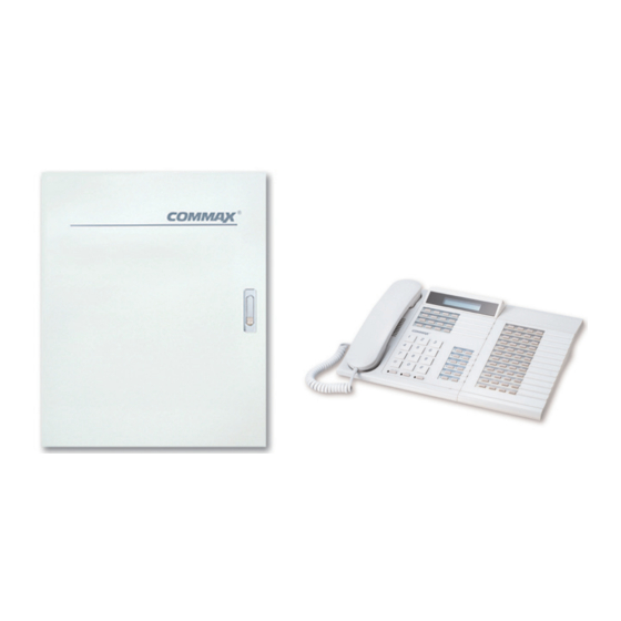
www.safemag.ru 1. System introduction This system was designed to exchange the communication between Nurse and patient with Master station and sub station by data communication system This system was composed with master station which can control and display in the system and Power controller, and the sub station was composed with 4 wire type and it can be covered maximum 32 ea sub station from 1 mater station, and It can be installed the presence switch, emergency switch and corridor light. -
Page 6: Signal & Lamp Specification
www.safemag.ru 4. Signal and Lamp Specification *If the situation will occur simultaneously, corridor light and master station lamp will blink at once. (Corridor light, shower room, bed, interphone will blink by turns) 5. How to use and Function 5.1 Bed Paging - Lift up the handset or press the programmed dial button to answer the call. -
Page 7: Presence Switch
www.safemag.ru 5.4 Presence switch 5.4.1 For emergency case, the nurse put the presence switch to inform the location with corridor lamp function and notifying to be reply for the master station’s call. 5.4.2 If the presence switch is on, the corridor lamp will be on display the master station. 5.4.3 To cancel the presence switch, put the presence switch it again. -
Page 8: Bed Programming
www.safemag.ru 1 - Switch (Interphone No.1) 64 - Switch (Interphone No.64) P - Reject switch for receiving the interphone broadcast For example) No. 43 can be received the interphone broadcast (1+2+8+32=43) For example) No. 43 can not be received the interphone broadcast (2+8+16+64=90) 7. -
Page 9: Bet No. And Inductor Set Up
www.safemag.ru 7.1 Bed No. and Inductor. - Press the mode button. (“password” will blink on the display window) - Enter the password (9999). (“Program” will blink on the display window) - Enter the code (00). (“pr00[0000]” will blink on the display window) - Use the button to be displayed pr010000] - Pr02 indicate the bed no., it can be input up to no.32. -
Page 10: How To Install Between Dss And Master Station
www.safemag.ru 8.2.2 Operating temperature shall be kept from 0C to 30C, Humidity shall be kept from 50% to 60%. 8.2.3 Power source shall be supplied at a convenient place for grounding and maintenance. 8.2.4 The system shall be installed to keep away from the electronic devices such as monitor, computer, etc. -
Page 11: Inductor
www.safemag.ru IN 2 Wire 4 Wire 1) Input 2 wire (IN01, IN02 ... IN16) shall be connected at a switch. 2) Output 2 wire shall be connected at each functional switch, if each input will be functional, the related output will be lighted. 8.7 Inductor Connection The inductor shall be connected as the following schematic. -
Page 12: Interphone 1
www.safemag.ru 8.8 Interphone Connection For TP-90AN connection or connection among the systems, the interphone shal l Main 1 Main 2 Interphone 1 Interphone 2 be connected with 10 pieces of cable by parallel. (Refer to the drawing no. 9-4) Main 1 Main 2 Interphone 1 Interphone 2... -
Page 13: Nurse Call System
www.safemag.ru 9. Nurse Call System Receiver to convert Receiver to be converted Power OFF Power ON 9.1 System Schematic www.safemag.ru... -
Page 14: System Wiring Diagram
www.safemag.ru 9.2 System Wiring Diagram www.safemag.ru 9.3 Parts Name and Connecting Method... -
Page 15: Parts Name And Connecting Method
www.safemag.ru 9.3 Parts Name and Connecting Method www.safemag.ru... -
Page 16: System Connection Schematic
www.safemag.ru 9.4 System Connection Schematic www.safemag.ru 9.5 Dimension... -
Page 17: Dimension
www.safemag.ru 9.5 Dimension 9.5.1 Master Station (JNS - 1060) 9.5.2 Main Control Panel (JNS - www.safemag.ru... - Page 18 www.safemag.ru 9.5.3 Console Bed (MGH - Series) 9.5.4 Sub Station (JNS - 101) 9.5.5 Emergency Switch (Toilet) (ES - 410) 9.5.6 Emergency Switch (Shower Room) (ES – 420) www.safemag.ru...
- Page 19 www.safemag.ru 9.5.7 Presence Switch (PB - 500) 9.5.8 Inductor 9.5.9 Corridor Light (CL - 302C) www.safemag.ru...
- Page 20 www.safemag.ru 9.6 Fitting Materials 9.5.10 Interphone 9.6.1 Coupling 9.6.2 Connector 9.5.11 Bed Head Calling Unit (PS - 100C) 9.6.3 Flexible Hose 9.5.12 Call Code (CC - 200) 9.6.4 UPT Cable 4P www.safemag.ru...
-
Page 21: Fitting Materials
www.safemag.ru 9.6 Fitting Materials 9.6.1 Coupling 9.6.2 Connector 9.6.3 Flexible Hose 9.6.4 UPT Cable 4P PE lscleled PVC/LSZH www.safemag.ru... - Page 22 www.safemag.ru 9.6.5 IV Cable 1.2mm Conductor Heat-reslsting PVC isolated 9.6.6 Concealed Box (Corridor Light) 9.6.7 Concealed Box (Emergency Switch) www.safemag.ru...
Need help?
Do you have a question about the JNS-PSM and is the answer not in the manual?
Questions and answers