Table of Contents
Advertisement
Quick Links
Advertisement
Table of Contents

Related Manuals for Pyramid CR10


Summary of Contents for Pyramid CR10
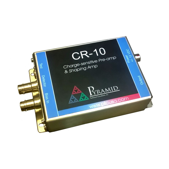
- Page 1 CR10 Combined Charge-sensitive Pre-amplifier and Shaping Amplifier User Manual Pyramid Technical Consultants, Inc. 1050 Waltham Street Suite 200, Lexington MA 02421 USA SUPPORT@PTCUSA.COM US: TEL: (781) 402 1700 FAX: (781) 402-1750 EMAIL: Europe: TEL: +44 1273 493590...
-
Page 2: Table Of Contents
Grounding and power supply ........................18 Connection to equipment ..........................18 9.3.1 Making connections ..........................18 9.3.2 Typical setup ............................18 9.3.3 Cables ..............................19 Circuit overview ............................... 21 Setup and Calibration ............................23 CR10 User Manual CR10_UM_180115 Page 2 of 40... - Page 3 Internal settings ............................30 14.5.1 Handling precautions ........................30 14.5.2 Accessing internal components ....................... 30 14.5.3 Cremat modules ..........................31 14.5.4 Jumpers ............................31 Fault-finding ..............................33 Maintenance ..............................35 Returns procedure ............................36 CR10 User Manual CR10_UM_180115 Page 3 of 40...
- Page 4 PSI System Controls and Diagnostics Support ................................37 Disposal ................................38 Declaration of Conformity ..........................39 Revision History ............................... 40 CR10 User Manual CR10_UM_180115 Page 4 of 40...
-
Page 5: Table Of Figures
Figure 1. CR10 chassis end panels (SHV connectors). Dimensions mm..............14 Figure 2. CR10 case plan and side views (SHV connectors). Dimensions mm............15 Figure 3. CR10 case (BNC signal connector option) end panel and plan view. Dimensions mm......16 Figure 4. DIN rail mounting............................17 Figure 5. -
Page 6: Safety Information
The unit is designed to make measurements in Measurement Category I as defined in the standard. Although the CR10 does not generate dangerous voltages, nor is it designed to measure directly such voltages, it may be supplied with high voltage bias up to +/- 3kV from an external supply. - Page 7 Direct current Earth (ground) terminal Protective conductor terminal Frame or chassis terminal Equipotentiality Supply ON Supply OFF CAUTION – RISK OF ELECTRIC SHOCK CAUTION – RISK OF DANGER – REFER TO MANUAL CR10 User Manual CR10_UM_180115 Page 7 of 40...
-
Page 8: Models
Example CR10-G1-T2-BR-N-IG1 CR10 configured with 130 mV pC-1 pre-amp conversion gain, 250 nsec shaping time constant, baseline restorer module, negative input pulse polarity and x1 intermediate stage gain. No connector type option was stated, so the unit will have SHV connectors as the default. -
Page 9: Scope Of Supply
PSI System Controls and Diagnostics 5 Scope of Supply CR10 model as specified in your order. USB memory stick containing: Data sheet User manual Test results Optional items as specified in your order. OEM customers may not receive all the items listed. -
Page 10: Optional Items
PSU-B12. +24 VDC to +/-12 VDC power supply, input for 2.1mm threaded jack, output 9 pin DSub female. Note: If the CR10 is used with a C400, +/-12V power is provided by the C400. 6.2 Cables and adaptors CAB-SHV-2-SHV HV cable assembly, 2’ (0.6 m). For signal input and HV bias input. -
Page 11: Intended Use And Key Features
The CR10 may be used to readout detectors that require bias voltage, either applied to the signal readout electrode or another electrode. Bias to the signal readout electrode is connected from the bias input internally in the CR10, and must be limited to +/- 3 kV which is the rating of the decoupling capacitors. -
Page 12: Specification
One volt step across 47 ohm gives 1 pC charge injection (nominal). Intermediate gain stage Polarity Jumper setting (order configuration option). -N non-inverting (for negative charge pulses at CR10 input) -P inverting (for positive charge pulses at CR10 input) Gain Jumper settings (order configuration option) -IG1... - Page 13 1 mm in size, protected against spraying water). Weight 0.29 kg (0.63 lb). Operating environment 0 to 35 C (15 to 25 C recommended to reduce drift and offset) < 80% humidity, non-condensing CR10 User Manual CR10_UM_180115 Page 13 of 40...
-
Page 14: Figure 1. Cr10 Chassis End Panels (Shv Connectors). Dimensions Mm
EPS.00.250.NTN DETECTOR BIAS IN +/-12V POWER IN LEMO EXG.0B.304.HLN OUTPUT LEMO COAX EPS.00.250.NTN FINE GAIN ADJUST OFFSET ADJUST POLE/ZERO ADJUST POWER LED Figure 1. CR10 chassis end panels (SHV connectors). Dimensions mm. CR10 User Manual CR10_UM_180115 Page 14 of 40... -
Page 15: Figure 2. Cr10 Case Plan And Side Views (Shv Connectors). Dimensions Mm
PSI System Controls and Diagnostics 62.0 80.5 3.66 SLOT 114.0 131.8 105.1 28.4 122.3 Figure 2. CR10 case plan and side views (SHV connectors). Dimensions mm. CR10 User Manual CR10_UM_180115 Page 15 of 40... -
Page 16: Figure 3. Cr10 Case (Bnc Signal Connector Option) End Panel And Plan View. Dimensions Mm
PSI System Controls and Diagnostics 80.5 62.0 3.66 SLOT 114.0 Figure 3. CR10 case (BNC signal connector option) end panel and plan view. Dimensions mm. CR10 User Manual CR10_UM_180115 Page 16 of 40... -
Page 17: Installation
(one meter) of coaxial cable can be used to connect the detector. This can be done to remove the CR10 from an area of high radiation for example, or to simplify mounting and cable connections. -
Page 18: Grounding And Power Supply
PSI System Controls and Diagnostics Best performance will be achieved if the CR10 is in a temperature-controlled environment. No forced-air cooling is required, but free convection should be allowed around the case. 9.2 Grounding and power supply A secure connection should be made via the mounting flange to local ground potential. If the unit is mounted on an insulating surface, then one of the four mounting screws must be re- assigned as a grounding connection. -
Page 19: Cables
Figure 5. Schematic CR10 installation for readout of a proportional chamber 9.3.3 Cables Try to locate the CR10 as close to the detector as possible, as far as space and radiation levels permit. Screened cable between the CR10 and the detector loads the input with capacitance, which affects both the noise level and the risetime of the input stage. -
Page 20: Figure 6. Effect Of Cable Capacitive Load On Noise
PSI System Controls and Diagnostics Effect of cable capacitance Length of RG-58 cable (cm) CR10-G0-T2 CR10-G0-T4 CR10-G1-T2 CR10-G1-T4 Figure 6. Effect of cable capacitive load on noise CR10 User Manual CR10_UM_180115 Page 20 of 40... -
Page 21: Circuit Overview
PSI System Controls and Diagnostics 10 Circuit overview The CR10 is based on proven reference circuit designs from Cremat, Inc. which have been integrated into a single compact device. The simplified schematic below shows the functional blocks. Typical signals present at stages A, B and C are in the subsequent figure. - Page 22 Incoming +/-12 V power is filtered and Zener diodes with transistor regulators produce the additional +/- 6.8 V and +/- 6.1 V rails required. A LED confirms that the +12 V supply is present. CR10 User Manual CR10_UM_180115 Page 22 of 40...
-
Page 23: Setup And Calibration
“pole” in the transfer function created by the preamplifier feedback resistor is cancelled by a “zero” created by the trimpot resistance in parallel with a capacitor inside the shaping amplifier. The potentiometer is set during manufacture to suit the combination of preamplifier and shaping CR10 User Manual CR10_UM_180115 Page 23 of 40... -
Page 24: Offset Correction
You will need to know at least one point to establish the calibration. As an example, you can calibrate a system comprising a silicon diode detector and the CR10 using a suitable monochromatic X-ray source. A convenient source is the Am-241 isotope which generates a 59.5 keV gamma ray which will create a measurable peak in a pulse height spectrum. -
Page 25: Figure 10. Measured Pulse Height Spectrum For Am-241 Gamma Line, Cr-110 And 1 Μsec Shaping
PSI System Controls and Diagnostics 59.5 keV, 2.6 fC Pulse height (mV, CR10-G0-T4) Figure 10. Measured pulse height spectrum for Am-241 gamma line, CR-110 and 1 µsec shaping Unknown X-ray peaks can then be assigned their energy by simple scaling. -
Page 26: Using The Test Input
A unipolar pulse output can be achieved if the test signal has a tail pulse shape (fast step followed by slow exponential decay). Figure 13. Injecting tail pulses to achieve a unipolar response to the test input CR10 User Manual CR10_UM_180115 Page 26 of 40... -
Page 27: Connectors
(less than 500 V). 13.1.3 Test Lemo 00 coaxial connector for test voltage input. Typical mating free connector Lemo FFA.00.250. 13.2 Rear panel connectors Output Power +/- 12 VDC Figure 15. Rear panel connectors CR10 User Manual CR10_UM_180115 Page 27 of 40... -
Page 28: Output
Lemo 0B four pin female, typical mating free connector FGG.0B.304. 1: -12 V 4: +12 V 2: AGnd 3: AGnd (LR) Connector body and pin 3 connect directly to CR10 analog ground. Pin 2 connects to analog ground via ferrite bead. CR10 User Manual CR10_UM_180115 Page 28 of 40... -
Page 29: Controls And Indicators
21-turn potentiometer for pole-zero adjustment. 14.2.3 Fine gain 21-turn potentiometer for fine gain adjustment. 14.3 Front panel indicators None. 14.4 Rear panel indicators Green LED indicates that incoming +12 VDC power is present. CR10 User Manual CR10_UM_180115 Page 29 of 40... -
Page 30: Internal Settings
PSI System Controls and Diagnostics 14.5 Internal settings We do not recommend that you open the CR10 case unless specifically instructed to do so by your supplier or Pyramid Technical Consultants, Inc. It is possible to damage the circuits or degrade noise performance if correct handling precautions are not employed. -
Page 31: Cremat Modules
POL: fit 2 mm jumper to switch in inverting intermediate amplifier stage. Use as appropriate to obtain positive polarity shaped output pulsed. Do not fit if the charge signals coming into the CR10 are negative polarity. Fit if the incoming charge signals are positive polarity. - Page 32 PSI System Controls and Diagnostics JPR2 Fit 2 mm jumper if no CR-210 baseline restorer is fitted. CR10 User Manual CR10_UM_180115 Page 32 of 40...
-
Page 33: Fault-Finding
Insufficient gain Look for pulses with increased Use appropriate charge- gain or more sensitive device sensitive preamplifier module connected to CR10 output. and intermediate gain settings. Reduce threshold of pulse counting discriminator circuits if possible. Wrong output pulse polarity –... - Page 34 Use correct impedance. 50 of two from expected values. resistance on readout device device. ohms is recommended for for CR10 pulse output. long transmission lines. Output has DC offset Offset trim is incorrect. Adjust trimpot to remove Adjust trimpot to remove offset.
-
Page 35: Maintenance
PSI System Controls and Diagnostics 16 Maintenance The CR10 does not require routine maintenance or calibration. There is risk of contamination which may degrade performance if the case is opened. If you need to access the unit to change amplifier modules or jumper settings, check first with your supplier or direct with Pyramid for guidance. -
Page 36: Returns Procedure
17 Returns procedure Damaged or faulty units cannot be returned unless a Returns Material Authorization (RMA) number has been issued by Pyramid Technical Consultants, Inc. If you need to return a unit, contact Pyramid Technical Consultants at support@ptcusa.com, stating - model... -
Page 37: Support
PSI System Controls and Diagnostics 18 Support Documentation updates are available for download from the Pyramid Technical Consultants website at www.ptcusa.com. Technical support is available by email from support@ptcusa.com. Please provide the model number and serial number of your unit, plus relevant details of your application. -
Page 38: Disposal
PSI System Controls and Diagnostics 19 Disposal We hope that the CR10 gives you long and reliable service. The CR10 is manufactured to be compliance with the European Union RoHS Directive 2002/95/EC, and as such should not present any health hazard. Nevertheless, when your device has reached the end of its working life, you must dispose of it in accordance with local regulations in force. -
Page 39: Declaration Of Conformity
PSI System Controls and Diagnostics 20 Declaration of Conformity CR10 User Manual CR10_UM_180115 Page 39 of 40... -
Page 40: Cr10 User Manual
PSI System Controls and Diagnostics 21 Revision History The release date of a Pyramid Technical Consultants, Inc. user manual can be determined from the document file name, where it is encoded yymmdd. For example, M10_UM_080105 would be a M10 manual released on 5 January 2008.
Need help?
Do you have a question about the CR10 and is the answer not in the manual?
Questions and answers