SpectraLink DECT Server 8000 Installation Manual
Hide thumbs
Also See for DECT Server 8000:
- Synchronization and deployment manual (36 pages) ,
- Manual (3 pages) ,
- Interoperability manual (31 pages)

Related Manuals for SpectraLink DECT Server 8000


Summary of Contents for SpectraLink DECT Server 8000
- Page 1 Spectralink DECT Server 8000 Installation Guide 14184630 version 8.0, K016 September, 2015...
- Page 2 The drawings and specifications contained herein are the property of Spectralink and shall be neither reproduced in whole or in part without the prior written approval of Spectralink, nor be implied to grant any license to make, use, or sell equipment manufactured in accordance herewith.
-
Page 3: Table Of Contents
Connecting the Spectralink DECT Server 8000 Cables ....... . . -
Page 4: Version 8.0, K016 September, 2015
Spectralink DECT Server 8000 Installation Guide Analogue Interface Card ............33 Base Station Interface Card for 4 channels Base Stations . -
Page 5: Spectralink Dect Server 8000 Installation
Installing the Spectralink DECT Server 8000 The DECT Server 8000 can be installed in a rack, on a flat surface or on a wall using the Spectralink DECT Server 8000 Wall Hanger. Before you start the installation, place the DECT Server 8000 on a stable flat surface in the selected location, and inspect the package for any damage and report it to the reseller or distributor immediately. -
Page 6: Power Consumption
Spectralink DECT Server 8000 Installation Guide Table 3 Power Consumption Power consumption Typical AC Power Consumption 90 Watt Max. AC Power Consumption Max 360 Watt Table 4 Environment Environment Operating temperature 0°C - 40°C (22° - 104°F) Storage temperature -30°C - 70°C (40° - 158°F) -
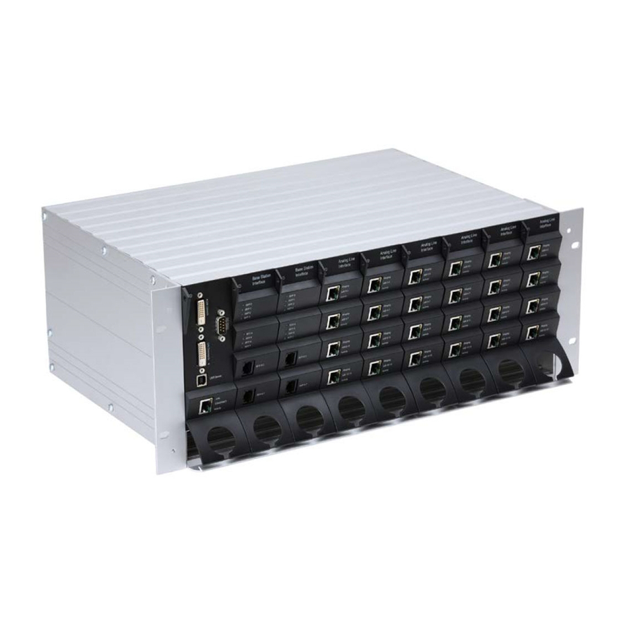
Page 7: Dect Server 8000 Components
Spectralink DECT Server 8000 Installation Guide DECT Server 8000 Components The following table contains all Spectralink DECT Server 8000 parts and their part numbers Table 5 DECT Server 8000 Components Picture Description Part Numbers Base Station Interface card (8 base... - Page 8 Spectralink DECT Server 8000 Installation Guide Table 5 DECT Server 8000 Components Picture Description Part Numbers Media Resource Card 0233 9700 Link cable 0233 9400 0233 8900 EU rack 0233 8901 US rack 0233 8902 UK rack Includes mains adapter and mains cable.
-
Page 9: Connections
Spectralink DECT Server 8000 Installation Guide Table 5 DECT Server 8000 Components Picture Description Part Numbers US mains cable 8468 7015 Terminator connector 0250 0300 RS232 cable 13281100 Connections Figure 1 CPU Card Connections Link upwards RS232 Link downwards Ethernet Note Link connections must not be left open. -
Page 10: General Installation Information
Media Resource Card Connection A Ethernet General Installation Information The maximum number of DECT Server 8000 units that can be linked together depends on the mounting method and the maximum length of the link cable: 14184630 Version 8.0, K016 September, 2015... -
Page 11: Installing The Spectralink Dect Server 8000 In A Rack
Keep the area around the Spectralink DECT Server 8000 clean and free of clutter. • Decide on a suitable location for the equipment rack that will hold the Spectralink DECT Server • 8000 unit. It should be situated in a clean, dry, and dust-free area that is well ventilated. Avoid areas where heat, electrical noise, and electromagnetic fields are generated. - Page 12 8000Spectralink DECT Server 8000 units any other units mounted in the rack. To Install the Spectralink DECT Server 8000 in a Rack You can install the Spectralink DECT Server 8000 in a rack using one of the two following methods: Install the brackets supplied by the rack manufacturer on each side of the rack on which the Spectralink DECT Server 8000 is placed.
-
Page 13: Installing The Dect Server 8000 On A Flat Surface
Never place anything, except ONE additional Spectralink DECT Server 8000 unit, on top of • the Spectralink DECT Server 8000. The top plate must be free to allow sufficient cooling. To Install the DECT Server 8000 on a Flat Surface Remove the Spectralink DECT Server 8000 from its package. -
Page 14: Connecting The Spectralink Dect Server 8000 Cables
Mount the wall hanger securely using four screws. Use rawlplugs, expansion bolts, or other appropriate fastening methods in relation to the wall material.Remove any drilling dust. Fit the DECT Server 8000 into the wall hanger, and fasten the two front screws. Figure 7... - Page 15 The AC adapters must never be hanging by their own weight in the AC mains connector or the • output connector. To Connect Power Cables The Spectralink DECT Server 8000 has four power plugs on the back panel behind the sliding doors: System Power Backup •...
-
Page 16: Installing Interface Cards And Cpu Cards
If more than two AC power adapters are used, these must be kept on a flat surface (same requirements as for the Spectralink DECT Server 8000 unit). In a rack installation the power adapters can be kept on a tray installed for the purpose provided that the ambient temperature is below 32ºCelcius/89,6º... - Page 17 Cables”. To Install CPU Cards Ensure that the Spectralink DECT Server 8000 is powered off completely. With two hands, gently slide the card into the unit. Give the card a gentle push on the last centimeter so that it enters the backplane connector properly.
- Page 18 Connect the power and reboot the unit. Connecting Interface Cables The front interface of the Spectralink DECT Server 8000 is provided with connectors for the different interfaces provided. Please see the Spectralink DECT Server 8000 Configuration Guide for the actual pin-out of the different connectors.
- Page 19 Spectralink DECT Server 8000 Installation Guide Figure 11 Harnessing cables to the back and out 14184630 Version 8.0, K016 September, 2015...
- Page 20 Spectralink DECT Server 8000 Installation Guide Figure 12 Harnessing cables to the side and out. Regardless of which way is used for harnessing, you must guide the cables through the opening in the plastic front. This ensures safe retention of the cable.
- Page 21 Spectralink DECT Server 8000 Installation Guide Connecting the Link Cable In installations where 2 or more Spectralink DECT Server 8000 units are linked together, it is important that the link cable is plugged into the proper port. Figure 13 Link Cable...
-
Page 22: Replacing Components
Spectralink DECT Server 8000 Installation Guide Chapter 2: Replacing Components The Spectralink DECT Server 8000 is designed to minimize down-time. Several components can be replaced while the system is up. Component Replacement The following components are hot-swappable: Interface cards •... -
Page 23: To Replace Or Install A New Cpu Card
To Replace or Install a New CPU Card Power off the Spectralink DECT Server 8000 completely. Ensure the Spectralink DECT Server 8000 unit is properly earthed. Unplug all interface cables on the card. Remove the cables from the opening in the plastic front. -
Page 24: Regulatory Notices
This equipment has a maximum operating ambient of 40°C. The ambient temperature in the • rack shall not exceed this temperature CE Mark R&TTE Directive SPECTRALINK declares that the SPECTRALINK DECT Server 8000 is in conformity with the following relevant harmonized standards: EN 60950-1:2006 + A11:2009 + A1:2010 EN 55022:2006 + A1:2007... -
Page 25: Canadian Department Of Communications
Spectralink DECT Server 8000 Installation Guide The WEEE Marking on this equipment indicates that the product must not be disposed of with unsorted waste, but must be collected separately. Canadian Department of Communications This Class [A] digital apparatus complies with Canadian ICES-003. -
Page 26: Warning
Spectralink DECT Server 8000 Installation Guide To reduce the risk of electrical shock or burns, do not disassemble this product. Opening or removing covers may expose you to dangerous voltages, dangerous electrical current, or other risks. Incorrect reassemble can cause electrical shock when the appliance is subsequently used. -
Page 27: Rf Compliance Information
SPECTRALINK may announce publicly from time to time for particular products, from the date of purchase from SPECTRALINK or its authorized reseller. - Page 28 (30) days after SPECTRALINK receives the defective product, and SPECTRALINK will retain risk of loss or damage until the item is delivered to Customer. EXCLUSIONS. SPECTRALINK will not be liable under this limited warranty if its testing and...
-
Page 29: End-User License Agreement For Spectralink Software
SOFTWARE PRODUCT ® licensed by SPECTRALINK, B.V in Europe, the Middle East, Africa, and Asia Pacific, or the SPECTRALINK SOFTWARE PRODUCT licensed by SPECTRALINK, Inc. in the rest of the world (collectively referred to herein as “SPECTRALINK”). The SOFTWARE PRODUCT includes computer software as attached hereto and may include associated media, printed materials, and "online"... - Page 30 This Agreement gives you no rights in such content. 2.7 Confidentiality. The SOFTWARE PRODUCT contains valuable proprietary information and trade secrets of SPECTRALINK and its suppliers and you shall protect the confidentiality of, and avoid disclosure and unauthorized use of, the SOFTWARE PRODUCT.
- Page 31 PRODUCT will be corrected. SPECTRALINK's sole obligation under this express warranty shall be, at SPECTRALINK's option and expense, to refund the purchase price paid by you for any defective software product which is returned to SPECTRALINK with a copy or your receipt, or to replace any defective media with software which substantially conforms to applicable SPECTRALINK published specifications.
- Page 32 NEITHER ASSUMES NOR AUTHORIZES ANY OTHER PERSON TO ASSUME FOR IT ANY OTHER LIABILITY IN CONNECTION WITH THE SALE, INSTALLATION, MAINTENANCE OR USE OF THIS SOFTWARE PRODUCT. SPECTRALINK SHALL NOT BE LIABLE UNDER THIS WARRANTY IF ITS TESTING AND EXAMINATION DISCLOSE THAT THE ALLEGED DEFECT...
- Page 33 10.3 Contact. If you have any questions concerning this Agreement, or if you desire to contact SPECTRALINK for any reason, please contact the SPECTRALINK office serving your country. 10.4 U.S. Government Restricted Rights. The SOFTWARE PRODUCT and documentation are provided with RESTRICTED RIGHTS.
- Page 34 Spectralink DECT Server 8000 Installation Guide Appendix A: RJ45 Wiring The following table shows the assignments of wire pairs to plug and socket pins of the RJ45 cable. Table 1 RJ45 cable wiring Pair Wiring Connector Connector Connector Connector ring...
-
Page 35: Analogue Interface Card
Spectralink DECT Server 8000 Installation Guide Appendix B: Cable Connections Analogue Interface Card Extensions from RJ45 to the Spectralink DECT Server 8000 the PBX Clip facing DOWN Base Station Interface Card for 4 channels Base Stations Base Station RJ45 to the Spectralink DECT Server 8000... -
Page 36: Base Station Interface Card For 8 Channels Base Stations
Spectralink DECT Server 8000 Installation Guide Base Station Interface Card for 8 channels Base Stations To use all 8 Channels in the Base Station, connection must be done as below: Note 4 & 8 channels Base Stations can be mixed in the set-up. - Page 37 Spectralink DECT Server 8000 Installation Guide Tables Physical Dimensions ......... . . 3 Power Supply .
- Page 38 ........DECT Server 8000 Power plugs 13...
- Page 39 Spectralink DECT Server 8000 Installation Guide 14184630 Version 8.0, K016 September, 2015...
Need help?
Do you have a question about the DECT Server 8000 and is the answer not in the manual?
Questions and answers