Table of Contents
Advertisement
Advertisement
Chapters
Table of Contents

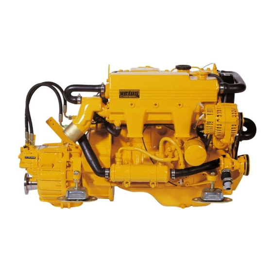
Summary of Contents for Vetus DIESEL VH4.65
- Page 1 VH4.65 VH4.80 Operation manual...
- Page 2 VH4.80 VD01079...
-
Page 3: Serial Numbers
VH4.65 Operation manual VH4.80 Serial numbers Engine serial number Vetus: Hyundai: Gearbox serial number: Please enter the serial numbers here. These numbers should be quoted when inquiring about Customer Service, Repairs or Spare Parts (see page 6). We reserve the right to make any changes without previous... - Page 4 The relevant accident prevention guidelines and other gene- For the Guarantee Conditions, see the Vetus Diesel Service and rally accepted safety and industrial hygiene regulations must be Warrantee Manual. observed.
-
Page 5: Table Of Contents
Contents Serial numbers Maintenance Cleaning the heat exchanger Checking engine rpm Checking the oil level 1 Introduction Checking the coolant level Checking and cleaning the Winter lay-up Engine description raw water strainer Winter storage procedure General Draining water from the water Recommissioning after winter Identification of engine parts separator/fuel filter... -
Page 6: Introduction
Introduction Dear Customer, Vetus diesel engines are designed both for pleasure and com- mercial craft. Consequently, a wide range of variants are offered to meet the requirements of specific cases. Your engine is appropriately equipped for your vessel, which means that not necessarily all components described in this manual are mounted to your engine. - Page 7 Introduction Safety measures All safety instructions in this manual are des- • Never attempt to touch moving parts when the engine is run- ignated by the accompanying symbol. Please ning. follow them carefully. • Never touch hot parts of the engine, and keep flammable materials well away from the engine.
-
Page 8: Engine Description
Engine description General VH480---A ø88 MM D4BB1207830 200001 4000 VD00232 VD01080 VD01081 Engine data tag Engine data tag location Engine serial number The v engine serial number and per- The v engine data tag is attached to The H engine serial number is etus etus yuNdai... - Page 9 Engine description General Port-side Lead seal Starboard Maximum rpm adjustment screw VD00229 VD00230 Cylinder numbering Fuel pump seal Cylinders are numbered consecutively, The manufacturer shall not be held liable Adjustments to the fuel beginning at the front end. for damages resulting from adjustments pump are to be carried out made to the fuel injection pump.
-
Page 10: Identification Of Engine Parts
Engine description Identification of engine parts Starboard 1 Airvent connection 2 Exhaust injection bend 5 6 7 VH4.65: ø 60 mm VH4.80: ø 75 mm 3 Lifting eye 4, 5 Cooling system drain plug 6 Heat exchanger 7 Expansion tank... - Page 11 Engine description Identification of engine parts Port-side 21 Oil dipstick 22 Oil filler cap 19 20 21 22 23 26 27 28 23 Fuel return pipe connection ø 8 mm 24 Calorifier connection, engine ‘OUT’ (ø 17 mm) 25 Electrical system connection box 26 Water separator/fuel filter air bleed nipple 27 Fuse...
-
Page 12: Control Panels
Engine description Control panels VD00103 VD00104 Basic panel (model 22) Extended panel (model 34) Fly-bridge panel (excl. voltmeter, model 21) - Page 13 Engine description Control panels VD00102 VD00101 Sailingboat panel (model 10) Push button panel (model 00) 1 Tachometer/Operating hours counter 10 Temperature gauge, coolant 2 Voltmeter 11 Oil pressure gauge 3 Starter pre-heat switch/lock 12 On push button switch 4 Warning light high raw water temperature 13 Pre-heating push button switch 5 Warning light low oil pressure 14 Starter push button switch...
-
Page 14: Use
General guidelines General guidelines for use Implementing the following recommendations will result in longer life and better performance and more economical operation of your engine. • Carry out the maintenance described regularly, including the ‘Daily procedures before starting’. • Use anti-freeze in the engine coolant all year long, this helps prevent corrosion as well as protecting against frost damage. -
Page 15: First Commissioning
First commissioning Engine Oil 4.9 litres (1.1 UKgal) 15W40 API: CD, CE or CF4 CCMC: D4, D5 For example: - Vetus Marine Inboard Diesel Motor - Shell Super Diesel T VD01082 Commissioning the engine Filling with engine oil Before starting the engine for the first time, As a rule engines are delivered empty of the following procedures must be carried oil. - Page 16 First commissioning Vetus engines are normally equipped with ZF-Hurth or Technodrive gear- boxes. In case your engine is equipped with another brand of gearbox follow the instructions given in the supplied own- ers manual. VD01100 Filling gearbox with oil ZF Hurth: Technodrive: Fill the gearbox with oil.
- Page 17 First commissioning oolant 7.1 litres (1.6 UKgal) quantity ater Heater If a water heater is connected to the engine and this heater is positioned above the upper side of the engine then bleeding of the heater will not take place automatically! Fill the heater separately to bleed the cooling system (3/8”) completely.
-
Page 18: Running-In
First commissioning Running-in Never fill the fuel tank while FUEL the engine is running. Do not spill fuel. Prevent unnecessary pollution. VD00002 Fuel Other preparations Running-in Ensure that the fuel tank is filled with • Check battery and cable connections. In order to ensure a long life for your diesel fuel. -
Page 19: Starting
Starting Before starting, check the follow- alWays ing points: neutral • Engine oil level. gearbox gearbox • Coolant level. reverse half throttle, forward • Sea cock open. gearbox not engaged • Main switch ‘ ’. • Gearbox in ‘ ’ position. Neutral forward reverse... -
Page 20: Pre-Heating
Starting arNiNg To prevent the glow plugs from burning out, never exceed the stated maximum pre-heating time. Maximum pre-heating time is 3 seconds. VD00107 VD00108 Pre-heating Turn the start key on the instrument panel Turn the key further clockwise to the ‘ ’... - Page 21 Starting arNiNg Release the key if the engine does not fire within 10 seconds. Wait until the starter motor has stopped running VD00109 completely before turning the key to the ‘ ’ position again. Never allow start the starter motor to run for more than 30 seconds consecutively.
-
Page 22: Cruising
If black smoke is emitted from the exhaust, in the first position, the voltmeter should this indicates that combustion is incom- Idling speed, indicate 12 Volts. plete. VH4.65 : 850 rpm If white smoke is emitted, this indicates VH4.80 : 850 rpm combustion of oil forced up. - Page 23 Cruising VD00663 VD00664 Temperature gauge Oil pressure gauge Warning lights Indicating the temperature of the internal With the engine at operating temperature, None of the five warning lights should light cooling system. the oil pressure is: up while the engine is running. Oil pres- The operating temperature is 76˚C - 85˚C.
-
Page 24: Stopping
Stopping VD00106 VD00105 Stopping Reduce engine speed to idle and shift the Never stop the engine immediately after N.B. The ‘s ’ position, left of the ‘o ’ gearbox to ‘N ’. Turn the key to the it has been in operation for a long time. position on the control panel, has normally eutral left to the ‘o... -
Page 25: Routine Maintenance
Routine Maintenance Introduction Introduction The following guidelines should be observed for daily and peri- odic maintenance. Perform each function at the indicated time interval. The intervals stated are for normal operational conditions. Service the unit more frequently under severe conditions. Failure to carry out maintenance can result in faults and perma- nent damage to the engine. -
Page 26: Maintenance Schedule
Routine Maintenance Maintenance schedule Every 10 hours or daily, before starting Every 500 hours, at least once every year Check engine oil level page 25 Gearbox oil change page 35 Check coolant level page 26 Replace fuel filter page 36 Check water strainer page 27 Cleaning fuel lift pump... -
Page 27: Maintenance
Maintenance Checking engine oil level Daily, before starting. VD01085 VD00231 VD01082 Check oil level Oil level Topping up oil Turn the engine off. The oil level must be at or near the upper The oil filling cap is on top of the the valve The dipstick is located on the port-side of mark on the dipstick*. -
Page 28: Checking The Coolant Level
Maintenance Checking coolant level Daily, before starting. VD01086 (3/8”) VD00144 VD01084 VD01083 Checking coolant level Topping up coolant Check the coolant level in the header tank. If necessary, top up. The internal cooling system can be filled This has to be checked when the engine with a mixture of anti-freeze (40 %) and tap is cold. -
Page 29: Checking And Cleaning The Raw Water Strainer
Maintenance Checking and cleaning the raw water strainer Daily, before starting. VD00125 CT30119 Checking the raw water strainer Cleaning the strainer Check daily whether there is any dirt in the Close the seacock before removing the lid Check the sealing between the lid and raw water strainer. -
Page 30: Draining Water From The Water Separator/Fuel Filter
Maintenance Draining of water from the water separator/fuel filter Every 100 operating hours. VD01087 VD00027 Empty fuel filter Empty water separator • Open the drain plug at the lower side of Empty the separately installed water sepa- the filter. rator/fuel filter: •... -
Page 31: Bleeding
Maintenance Draining of water from the water separator/fuel filter Every 100 operating hours. VD00107 VD01088 VD00109 Bleeding Start the engine After the water separator/fuel filter has Open the bleeding nipple to speed up the Operate the starter switch until the engine been drained, the air has to be bled from bleeding process. -
Page 32: Battery, Cables And Cable Connections
Maintenance Battery, cables and connections Every 100 operating hours. Vetus maintenance-free batteries Green Dot All Dark clear VD00117 VD00118 VD00121 VD00122 VD00123 Battery, battery connections Checking specific gravity Hydrometer operation Keep battery clean and dry. • Green dot visible - State of charge Every Vetus Maintenance-free battery has Remove battery cables (negative first). - Page 33 Maintenance Battery, cables and connections Every 100 operating hours. Conventional batteries Conventional batteries Specific State of gravity charge 1.280 100% 1.200 recharge 1.120 recharge immediately VD00119 VD00120 Checking electrolyte level Checking specific gravity The gases emitted by the battery are explosive! Keep For conventional batteries it is required Measure the electrolyte specific gravity sparks and naked flames...
-
Page 34: Changing The Oil
Maintenance Engine oil change Every 250 operating hours. Engine oil change Change the engine oil every 250 hours of operation (together with engine oil filter replacement). If the engine runs less than 250 hours dur- ing the year the oil should be changed at least once a year. - Page 35 Maintenance Engine oil change Every 250 operating hours. : StM4910 Mount of oil liefilter Code 5.5 litres (1.2 UKgal) oil filter inCl VD00030 VD01091 VD01082 Oiling the oil seal Oil filter installation Refilling with oil Clean the contact surface of the gasket. Install the filter in accordance with the Refill the engine with new oil (for specifica- Lubricate the oil seal of the new filter ele-...
- Page 36 Maintenance Gearbox oil level check Every 100 operating hours. VD01109 Oil level check (ZF-Hurth) Unscrew the dipstick out of the gearbox Vetus engines are normally equipped housing. with ZF-Hurth or Technodrive gearbox- es. Consult the supplied Owners Manual The oil level must between the two marks for more details about care and mainte- on the dipstick.
-
Page 37: Changing The Gearbox Oil
Maintenance Changing the gearbox oil Every 500 operating hours. VD01102 VD01100 Draining the oil Filling with new oil Drain the oil with the aid of a separate Refill the gearbox to the correct level via In case your engine is equipped with sump pump. -
Page 38: Replacing The Fuel Filter
Maintenance Fuel filter replacement Every 500 operating hours. : StM3690 randStoffilter Code VD01093 VD00154 VD00133 Fuel filter removal Fuel filter installation The fuel filter is to be replaced as a unit. • Clean any debris from the filter carrier • Close the fuel stopcock. rim. -
Page 39: Cleaning Fuel Lift Pump
Maintenance Cleaning fuel lift pump Every 500 operating hours. : StM4050 randStoffilter Code Fuel filter STM7220 VD00109 Fuel lift pump Bleeding Start the engine • Check, and if necessary clean, filter After replacing the fuel filter and cleaning Operate the starter switch until the engine inside the fuel lift pump. -
Page 40: Checking The V-Belts
Maintenance Checking the V-belts Every 500 operating hours. V-belt alternator/ coolant pump, V-belt raw water pump, art.code: STM4509 art.code: STM4523 VD00034 VD00238 VD00239 Inspection V-belts Checking tension V-belt alternator/ Checking tension V-belt raw water coolant pump pump Inspect the belts for wear and tear (fray- Check tension of the V-belt by applying Check tension of the V-belt by applying ing and cracking). - Page 41 Maintenance Checking the V-belts Every 500 operating hours. VD01112 VD01111 Tensioning V-belt alternator/coolant Tensioning V-belt raw water pump pump Loosen the bolts of the adjustment bracket Loosen the bolt of the adjustment bracket (1 and 2) and the alternator mounting bolt (1) and the mounting bolts (2 and 3).
-
Page 42: Checking Flexible Engine Mounts
Maintenance Flexible engine mounts, hose connections and fasteners Every 500 operating hours. VD00160 VD01103 Check flexible engine mounts Inspection hose connections Check fasteners Check the bolts which secure the damper Inspect all hose connections of the coo- Check tightness of all fasteners, bolts and element, the mounting bolts to engine bed lingsystem. -
Page 43: Checking Valve Clearance
Maintenance Checking valve clearance Every 1000 operating hours. VD00247 VD01092 Checking / adjusting valve clea- Remove distribution cover Remove rocker cover rance Remove the 5 bolts of the distribution Remove the 3 bolts of the rocker cover. cover. Complete the following steps: Checking the valve clearance must be done with a cold engine, that is an engine which did not run for at least 6 hours. -
Page 44: Check Valve Clearance
Maintenance Checking valve clearance Every 1000 operating hours. 0.15 mm (0.006”) alVe ClearanCe nlet Mark on 0.15 mm (0.006”) gearcase xhauSt TDC mark Port-side cylinder 1 and 4 Starboard VD00246 VD00248 VD01110 Locating TDC Adjusting valve clearance Locate the Top Dead Center (TDC), at the •... - Page 45 Maintenance Checking valve clearance Every 1000 operating hours. Port-side Port-side Starboard Starboard VD00249 VD00229 Adjusting valve clearance Cylinder numbering • Rotate the crankshaft 360° clockwise. Cylinders are numbered consecutively, • Check valve clearance at indicated beginning at the front end. valves and adjust if necessary.
-
Page 46: Raw Water Pump Inspection
Maintenance Raw water pump inspection Every 1000 operating hours. 1,6 x 6,3 VD01095 VD01096 VD01031 Raw water pump inspection Pump cover removal Impeller removal The rubber impeller of the outboard water Inspection where appropriate changing is • Slide the impeller off of the shaft using pump is not proof against running dry. - Page 47 Maintenance Raw water pump inspection Every 1000 operating hours. : StM4652 : StM4656 Mpeller Code akking Code VD00127 VD00004 VD00159 Impeller inspection Re-install the impeller Replacing the pump cover • Inspect the impeller for damage. • The impeller should be lubricated with •...
-
Page 48: Coolant Replacement
Maintenance Coolant replacement Every 1000 operating hours. Coolant replacement The coolant has to be replaced every 1000 operating hours or at least once every two years. N.B. Replacing the coolant may also be necessary as part of the winter storage procedure;... - Page 49 Maintenance Coolant replacement Every 1000 operating hours. oolant 7.1 litres (1.6 UKgal) quantity ater Heater If a water heater is connected to the engine and this heater is positioned above the upper side of the engine then bleeding of the heater will not take place automatically! Fill the heater separately to bleed the cooling system (3/8”)
-
Page 50: Cleaning The Heat Exchanger
Maintenance Cleaning the heat exchanger VD01098 VD01086 VD01113 Remove the drain plug Removal of exhaust injection bend • Close the seacock and detach the • Remove the filler cap from the top of the Remove the 4 bolts of the exhaust injec- water inlet hose from the sea water heat exchanger housing to allow air into tion bend. -
Page 51: Cleaning Heat Exchanger
Maintenance Cleaning the heat exchanger VD01116 VD01115 STM7217 VD01114 Cleaning the heat exchanger Removal of bolts out of the end covers Slide the heat exchanger out of the hou- sing. Take out both central bolts from the end covers and take the end covers with the Clean the heat exchanger: Use a pipe O-rings out of the housing. - Page 52 Maintenance Cleaning the heat exchanger : StM6113 (2 ring Code VD00233 VD00234 Replacing heat exchanger Replacing the end covers Replace the heat exchanger in the original Fit the end covers in the housing; the con- Tighten up the bolts when both covers are position in the heat exchanger housing.
-
Page 53: Checking Engine Rpm
Maintenance Checking engine speed Increasing arNiNg Minimum The maximum engine speed adjust- speed adjustment ment screw has been correctly set screw at the factory and sealed. DO NOT attempt to remove this seal. Lead seal Maximum rpm adjustment screw VD00134 VD00230 Checking engine speed Adjusting engine idling speed... -
Page 54: Winter Lay-Up
Winter lay-up Winter storage procedure VD01087 VD00136 Fuel system Running with protective fuel mixture Drain the water from the water separator/ Connect the fuel supply pipe to a can filled * Engine oil with protective properties. fuel filter and the fuel tank. Ensure that the with a mixture of one (1) part of engine oil* E.g. - Page 55 Winter lay-up Winter storage procedure VD01089 VD00125 Lubrication system Raw water cooling system With the engine still at operating tempe- Close the seacock before removing the lid Check the seal between the lid and hou- rature: (If not, run the engine until warm, of the water strainer.
- Page 56 Winter lay-up Winter storage procedure VD01086 VD00139 VD001xx Fresh water cooling system Electrical system Charging the batteries To avoid corrosion during winter storage Disconnect the battery cables. Charge batteries during winter lay-up the cooling system must be filled with an regularly if required! antifreeze/water mixture (or a coolant).
-
Page 57: Recommissioning After Winter Storage
Winter lay-up Recommissioning after winter storage Check that the lid of the raw water Open the sea cock. strainer is reinstalled. VD00125 VD00138 Check that the lid of the raw water Check the coolant level. (page 26) pump and drain plugs are reinstal- led. - Page 58 Winter lay-up Recommissioning after winter storage Drain the water from the water sepa- Open the fuel valve. rator/fuel filter. (page 28) VD00027 VD00137 Drain the water from the fuel tank. Make sure that the batteries are fully charged. (pages 30, 54) VD00141 CT40063 Install a new fuel filter.
- Page 59 Winter lay-up Recommissioning after winter storage Start the engine. Check the fuel system, the cooling system and the exhaust for leakage. VD01108 Stop the engine and change the oil of the gearbox. (page 35) VD01102 Check the operation of the instru- ments, the remote control and the gearbox.
-
Page 60: Troubleshooting
Troubleshooting General Engine faults are in most cases caused by improper operation or insufficient maintenance. In case of a fault, always check first that the operation and main- tenance instructions have been followed. In the following tables information is given about the possible causes of faults and suggested remedies. - Page 61 Troubleshooting Fault finding table 1 Engine will not crank 2 Engine cranks but will not start, no smoke from exhaust Possible fault Remedy Possible fault Remedy Faulty or discharged battery. Check / recharge bat- Fuel stop valve closed. Open. tery and check engine (Nearly) Empty fuel tank.
- Page 62 Troubleshooting Fault finding table 3 Engine cranks but will not start, smoke from exhaust 4 Engine starts but runs unevenly (rough idling) or stalls Possible fault Remedy Possible fault Remedy Air in fuel system. Check and bleed. (Nearly) Empty fuel tank. Refill.
- Page 63 Troubleshooting Fault finding table 5 Engine does not reach maximum rpm under load 6 Engine overheats Possible fault Remedy Possible fault Remedy Air in fuel system. Check and bleed. Faulty injector/injection pump. Check, replace if Fuel filter clogged with water Check or replace.
- Page 64 Troubleshooting Fault finding table 7 Engine not firing on all cylinders 8 Engine has little or no oil pressure Possible fault Remedy Possible fault Remedy Air in fuel system. Check and bleed. Oil level too low. Increase level. Fuel filter clogged with water Check or replace.
- Page 65 Troubleshooting Fault finding table Blue exhaust smoke (idling) White exhaust smoke (at full load) Possible fault Remedy Possible fault Remedy Oil level too high. Lower level. Air in fuel system. Check and bleed. Excessive inclination of engine. Check / Adjust. Faulty injector/injection pump.
-
Page 66: Technical Data
Technical data Engine specifications Model VH4.65 VH4.80 Model VH4.65 VH4.80 General Maximum output Make Vetus Hyundai at the flywheel (ISO 3046-1) 48 kW (65.3 hp) 59 kW (80.3 hp) Number of cylinders at the prop shaft (ISO 3046-1) 46.6 kW (63.4 hp) 57.2 kW (77.6 hp) - Page 67 Technical data Engine specifications Model VH4.65 VH4.80 Model VH4.65 VH4.80 Exhaust system Oil lubrication system Exhaust diameter 60 mm 75 mm Oil capacity, max. Exhaust back pressure at specified output without oil filter 4.9 litres (1.1 UKgal) max. 150 mbar (2.2 psi) with oil filter 5.5 litres (1.2 UKgal)
-
Page 68: Operating Media
Operating media Lubricating oil Engine Lubricating Oil Gearbox Lubricating Oil Only use a recognised brand of oil for lubricating the engine. Only use a recognised brand of oil for lubricating the gearbox. Lube oils are differentiated according to their performance and ZF Hurth: quality class. -
Page 69: Fuel
Operating media Fuel Fuel Quality Grade Winter-grade fuel Use commercially available diesel fuel with less than 0.5% sulfer Waxing may occur at low temperatures, clogging the fuel system content. If the sulfur content is higher than 0.5%, the intervals and reducing engine efficiency. between oil changes should be halved e.g. -
Page 70: Coolant
Operating media Coolant Coolant fluid Water quality for coolant preparation Use preferably tap water. The preparation and monitoring of coolant in inter-cooled engines is especially important because corrosion, cavitation and freezing If an other available fresh water is used; the values given below can lead to engine damage. -
Page 71: Wiring Diagrams
Wiring diagram Engine with panel model ‘20’, ‘21’, ‘22’ Engine panel model Key switch Tachometer/ Voltmeter hour counter '20' '21' '22' Model 20 21 22 Voltmeter Tachometer - 17/19 Warning lights Yellow Orange Violet White Black Plug 'A' Gearbox oil press. Socket 'A' Fuse or circuit breaker... - Page 72 Wiring diagram Options, panel model ‘34’ Key switch Tachometer/ Oil pressure Temperature Engine panel model Voltmeter hour counter gauge gauge '34' ϑ 17/19 Warning lights Gearbox oil press. Ð Pre- 19/94 (31) (15) heating Yellow Orange Violet White Black Interface Plug 'A' STM6911 Socket 'A'...
- Page 73 Wiring diagram Options, panel model ‘10’ Engine panel model Key switch '10' 17/19 Warning lights Yellow Orange Violet White Black Plug 'A' Socket 'A' Fuse or circuit breaker Auxiliary start relay Pre- heating 19/94 Pre- heating Stop relay Plug 'B' relay Socket 'B' Battery...
-
Page 74: Overall Dimensions
Overall Dimensions VH4.65 1:10 VD00235... - Page 75 Overall Dimensions VH4.80 1:10 VD00236...
- Page 79 Manual de servicio y garantía / Libretto di assistenza e garanzia Español / Italiano / Service- og garantibog / Service- och garantihäfte Dansk / Svenska) 351131.06 (STM4992) Onderdelenboek / Parts manual VH4.65 / VH4.80 (Nederlands / English) 352102.01 Service manual VH4.65 / VH4.80 (English)
- Page 80 vetus n. v. FOKKERSTRAAT 57 - 3125 BD SCHIEDAM - HOLLAND - TEL.:+31(10) 4377700 FAX:+31 (10) 4372673 - 4621286 - E-MAIL: sales@vetus.nl - INTERNET: http://www.vetus.com 350102.01 06-08 (STM4994) English Printed in the Netherlands...