Advertisement
Table of Contents
- 1 Table of Contents
- 2 Warnings
- 3 Mount Definitions
- 4 Controller Views
- 5 Configuration and Software Versions
- 6 Menus and Operations
- 7 Connector Wiring Diagram
- 8 Raising the ODU Using a 12 VDC Source
- 9 SWM Directv Block Diagram
- 10 Dish Network / Dish Network Hopper 3
- 11 SHAW Block Diagram
- 12 Foot Print and Clearances
- 13 Returning Parts to the Factory
- Download this manual
Advertisement
Table of Contents

Related Manuals for RF Mogul EAGLE II

Summary of Contents for RF Mogul EAGLE II
- Page 1 SATELLITE TV OPERATION / TECHNICAL MANUAL Eagle II Controller 10 May 2018...
- Page 2 Eagle Manual...
-
Page 3: Table Of Contents
Eagle Manual ndex Warnings ....... Mount Definitions ......Controller Views ....... Configuration and Software Versions ....... Menus and Operations ....... Connector Wiring Diagram ....... Raising the ODU Using a 12 VDC Source ....... SWM DirecTV Block Diagram ....... ……………… Dish Network / Dish Network Hopper 3 ………………... -
Page 4: Warnings
Eagle Manual WARNING Double check all electrical and coax connections from the controller to the mount and LNB's BEFORE applying power to or connecting the satellite receiver to the controller Note: The control cable has 12 wires that control motors, provides GPS information and sensor feedback. -
Page 5: Mount Definitions
Eagle Manual ount definitions MOUNT (ODU) A system consists of several components Reflector/Parabola Stow Brackets Note: Your LNB may vary from the one pictured depending upon your system configuration. Mount or Azimuth Base LNB Arm Assembly Connector Weather Cover Mounting Feet Items included with the system and are not shown. -
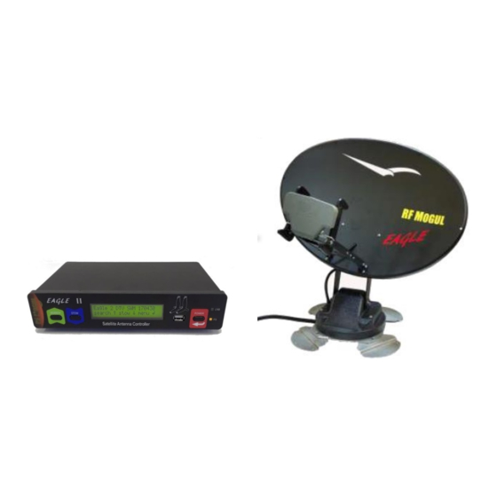
Page 6: Controller Views
Eagle Manual ontroller Views FRONT VIEW Definitions and Usage CONTROLLER (IDU) SEARCH Directs the system to "FIND" Satellites. Also navigates through the menus. STOW Directs the system to "STOW" the mount and prepare it for travel Also navigates through the menus. LCD Display Displays the actions of the system. - Page 7 Eagle Manual REAR VIEW Definitions and Usage CONTROLLER (IDU) To REC To LNB CONNECTIONS 12 VDC: (Power) 12 VDC 7 amp (power supply provided). CONTROL CABLE CONNECTION: Termination of the 12 wires of the control cable to the controller takes place here. TO REC: (To Satellite Receiver) This is a coax pass-through connection to your satellite receiver (Satellite IN).
-
Page 8: Configuration And Software Versions
Eagle Manual onfigurations and Software Version Each of the Program Providers will require different software EAGLE SHAW Direct = 107.3, 107.3, 111.1 Satellites (For Canadian Use Only) EAGLE DirecTV SWM = 99, 101, 103 Satellites EAGLE Dish Network = 110, 119, 129 Satellites EAGLE Bell TV = 81, 92 Satellites... -
Page 9: Menus And Operations
Eagle Manual enu Options Menus and Operation Your controller is menu driven. By selecting a particular menu, you can perform many functions besides just "SEARCHING for satellite". TO SEARCH • Press the Power button o Displayed will be the..▪ System configuration (software configuration) •... - Page 10 Drive. You can use Google Search “lat/lon • Call RF Mogul for the software for your application. Make sure that it is placed in the of Reno, NV” if you are in the city of "root directory" and that no other “. hex” file is in Reno, NV.
-
Page 11: Connector Wiring Diagram
Eagle Manual onnector Wiring Diagram Wiring the 12 Pin Controller Connector MOVING THE ANTENNA USING A 12 VDC SOURCE After removing the appropriate wires from the 12 Pin Green Connector, touch the following wires from the control cable directly to any +/- 12 VDC source, such as the 12-volt source located at the back of the controller or a drill battery. -
Page 12: Swm Directv Block Diagram
21 Volt Power Inserter 4 Port splitter shown. Do not use a 29-volt 8 Port splitter is available Power Inserter with a RF Mogul System 110 Volts AC Receiver #1 Receiver #2 This DirecTV SWM Installation Receiver #3 Does not represent the Genie 3 that has a built in Power Inserter. -
Page 13: Dish Network / Dish Network Hopper 3
Eagle Manual... -
Page 14: Shaw Block Diagram
SHAW Block Diagram Note: The SHAW system can be ordered with 4 coax cables. Standard configuration of the RF Mogul System is 3 coaxes unless ordered with 4. Most RV installations can survive with 3 (Two receivers, one non-DVR and one Dual Tuner. (Some SHAW DVR’s take 2 coaxes. Single tuner non-DVR receivers use only one coax. -
Page 15: Foot Print And Clearances
Eagle Manual ootprint and Clearances 35.5 Inches 8 1/2 Inches 13 1/2 Inches Distance for installing LNB Landing Plate Rotational clearance from center rotation point is 18 inches when dish is elevated and rotating. This is a safety zone. CONTROLLER Dimensions 33.5 Inches 10"... -
Page 16: Returning Parts To The Factory
Parts returned to the factory must contain a Return Material Authorization (RMA) which will be provided by the RF Mogul Technical Support Department at the time of troubleshooting. This will ensure proper accountability of returned equipment or parts. Make sure that the following information is contained on your shipment.
Need help?
Do you have a question about the EAGLE II and is the answer not in the manual?
Questions and answers
Used satellite yesterday and worked great. Stowed this morning to move to new site within a couple hundred feet with same open sky. Now searching for gps. Tried several times but it won’t lock in. What do I do