Table of Contents
Advertisement
SERVICE MANUAL
Wall Mounted Type
ON/OFF
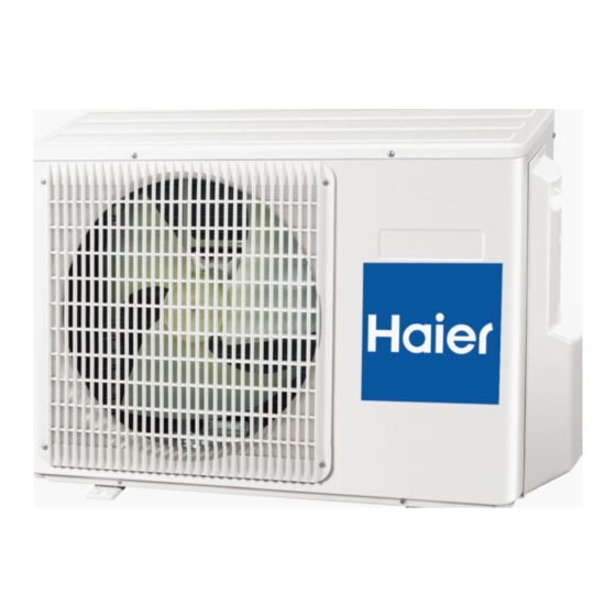
Model No.
1U18BR4EAA
HSU-18HUN103/R2
WARNING
This service information is designed for experienced repair technicians only and is not designed for use by the general public.
It does not contain warnings or cautions to advise non-technical individuals of potential dangers in attempting to service a product.
Products powered by electricity should be serviced or repaired only by experienced professional technicians. Any attempt to service or
Repair the product or products dealt with in this service information by anyone else could result in serious injury or death
2017 (Qingdao Haier Air Conditioner General corp. , Ltd)
All rights reserved. Unauthorized copying and distribution is a violation of law
Haier Group
Version V1
Date 2017-03-07
Advertisement
Table of Contents

Subscribe to Our Youtube Channel
Summary of Contents for Haier 1U18BR4EAA
- Page 1 Repair the product or products dealt with in this service information by anyone else could result in serious injury or death 2017 (Qingdao Haier Air Conditioner General corp. , Ltd) All rights reserved. Unauthorized copying and distribution is a violation of law...
-
Page 2: Table Of Contents
Contents Contents 1. Introduction ....................1 2. Specifications..................7 3. Piping diagrams ..................9 4. Operation range ..................10 5. Circuit diagrams .................. 6. Dimensional drawings................7. Center of gravity ................... 8. Service Diagnosis ................9. Perfomance Curves Diagram..............18 Domestic air conditioner... -
Page 3: Introduction
Introduction 1 Introduction 1.1 Model name explanation Apply toT1; 220~240V50HZ/1ph Heat pump & R410A refrigerant Version number District Platform of outdoor units:E Platform Nominal cooling capacity (18000BTU/h) Type of outdoor unit : U (normal type) The maximum combination number Domestic air conditioner... - Page 4 ...
- Page 5 ...
- Page 6 ...
- Page 7 ...
- Page 8 ...
-
Page 9: Specifications
Specification 2 Specifications NOMINAL DISTRIBUTION SYSTEM VOLTAGE NOMINAL CAPACITY and NOMINAL INPUT n i l Platform of indoor units Capacity rated Power Consumption(Rated) KW 1.470 1.460 1.620 1.610 1.460 1.610 3.23 3.63 3.23 3.63 ³ 2.0*10 TECHNICAL SPECIFICATIONS-UNIT Dimensions H*W*D 780×245×640 Packaged H*W*D... - Page 10 Specification TECHNICAL SPECIFICATIONS-OTHERS Refrigerant type R410a Refrigerant charge 1.35 Refrigerant Maximum allowable distance circuit between indoor an outdoor Maximum allowable level difference Refrigerant control Capillary liquid 6.35 Piping connections 12.7 (external diameter) drain Heat insulation type Both liquid and Gas pipes Max.
-
Page 11: Piping Diagrams
Piping diagrams 3 Piping diagrams Domestic air conditioner... -
Page 12: Operation Range
... -
Page 13: Circuit Diagrams
Circuit Diagram Circuit Diagram OUTDOOR DIAGRAM 0010560078 TO INDOOR UNIT 1(L) 2(N) FRESH AIR MOTOR W(orBorBR) CAPACITOR CAPACITOR 4-way valve TO INDOOR COMPRESSOR FRESH AIR MOTOR FAN MOTOR NOTE: BL:BLUE 1.See above for wiring of heat pump type. 2.There are no dotted lines on cool only type.(marked BLACK with @),Wire is connected from 4 (marked with @@)on terminal block to 1. -
Page 14: Dimensional Drawings
Dimensinal drawings 6.Dimensional drawings 12.7 unit:mm 7.Center of gravity unit:mm Domestic air conditioner... -
Page 15: Service Diagnosis
Service diagnosis 8 Service Diagnosis 8 .1 Caution for Diagnosis The operation lamp flashes when any of the following errors is detected. 1. When a protection device of the indoor or outdoor unit is activated or when the thermistor malfunctions, disabling equipment operation. - Page 16 Service diagnosis 8.3 Problem Symptoms and Measures Symptom Check Item Details of Measure Check the power supply. Check to make sure that the rated voltage is supplied. None of the units operates Check the indoor PCB Check to make sure that the indoor PCB is broken Operation A power failure of 2 to 10 cycles can stop air conditioner Check the power supply.
- Page 17 Seivice diagnosis 8.4Codes and Description 8.4.1.Problem Symptoms and Measures Symptom Check Item Details of Measure Check to make sure that the rated voltage is None of the units Check the power supply. supplied. operates Check the indoor PCB Check to make sure that the indoor PCB is broken Equipment operates but does Diagnosis...
- Page 18 Seivice diagnosis Check the connector connection. Correct the connection Is it normal? Thermistor resistance check Replace the thermistor Is it normal? Replace the indoor unit PCB Thermistor resistance check method: Remove the connector of the thermistor on the PCB, and measure the resistance of thermistor using tester. The relationship between normal temperature and resistance is shown in the value of indoor thermistor.
- Page 19 Service diagnosis 8.4.2.3 Indoor DC fan motor malfunction Indoor Display Method of Method of The rotation speed detected by the Hall IC during fan motor operation is used to determine Method of Malfunction Malfunction abnormal fan motor operation Malfunction Detection Detection Detection Malfunction...
-
Page 20: Perfomance Curves Diagram
Performance Curves Diagram 9 Performance Curves Diagram 9.1 Cooling capacity-temperature curves Domestic air conditioner... - Page 21 Performance Curves Diagram 9.2 heating capacity-temp.curves Domestic air conditioner...
- Page 22 Performance Curves Diagram 9.3 Cooling power consumption-temp.curves Domestic air conditioner...
- Page 23 Performance Curves Diagram 9.4 heating power consumption-temp.curves Domestic air conditioner...
- Page 24 The end Sincere Forever Haier Group Edited by : Wang Fang Haier Industrial Park, No.1, Haier Road Yang Xiaodong 266101, Qingdao, China_ Signed by : He shiquan Http //www.haier.com Approved by: Wu Hongjin Domestic air conditioner...
- Page 25 ...
- Page 26 1. Removal of outdoor panel...
- Page 27 1. Removal of Electrical Box...
- Page 30 2. Removal of Electrical Box...
- Page 32 9.12 Removal of fan motor bracket and partition...
- Page 34 9.13 Removal of compressor and heat exchanger...


Need help?
Do you have a question about the 1U18BR4EAA and is the answer not in the manual?
Questions and answers