Table of Contents
Advertisement
Quick Links
Primary Glass Panel Engine Monitor
Primary Glass Panel Engine Monitor
Primary Glass Panel Engine Monitor
Primary Glass Panel Engine Monitor
Primary Glass Panel Engine Monitor
Installation Instructions
Installation Instructions
Installation Instructions
Installation Instructions
Installation Instructions
You must read this manual before installing or operating the instrument. This
manual contains warranty and other information that may affect your decision
to install this product and/or the safety of your aircraft.
The CGR-30C is a FAA Approved Primary Replacement
for Engine and Aircraft System Instruments
Electronics International Inc.
Electronics International Inc.
Electronics International Inc.
Electronics International Inc.
Electronics International Inc.
63296 Powell Butte Hwy
63296 Powell Butte Hwy
63296 Powell Butte Hwy
63296 Powell Butte Hwy
63296 Powell Butte Hwy
CGR-30C
CGR-30C
CGR-30C
CGR-30C
CGR-30C
II 10291301
Model #:
Model #:
Model #:
Model #:
Model #:
S/N:
S/N:
S/N:
S/N:
S/N:
•
•
•
Bend, OR 97701
Bend, OR 97701
Bend, OR 97701
•
•
Bend, OR 97701
Bend, OR 97701
•
•
•
(541) 318-6060
(541) 318-6060
(541) 318-6060
• Buy-EI.com
• Buy-EI.com
• Buy-EI.com
•
•
(541) 318-6060
(541) 318-6060
• Buy-EI.com
• Buy-EI.com
Rev: B, 5/11/15*
® ® ® ® ®
Advertisement
Table of Contents

Related Manuals for Electronics International CGR-30C


Summary of Contents for Electronics International CGR-30C
- Page 1 You must read this manual before installing or operating the instrument. This manual contains warranty and other information that may affect your decision to install this product and/or the safety of your aircraft. The CGR-30C is a FAA Approved Primary Replacement for Engine and Aircraft System Instruments Model #:...
- Page 2 DO NOT INSTALL THIS PRODUCT. Contact Electronics International Inc. for details. Electronics International Inc. is not liable or responsible for a pilot’s action or any situation that results in personal injury, property damage, missed commitments, lack of use of an aircraft or any...
- Page 3 ***** MUST READ ***** Page 2 of 4 Do not install a non-certified CGR-30C (CGR) in a certified aircraft. A certified CGR lists the applicable TSO numbers at the bottom of the Model Label. Before starting the installation make sure the unit will fit in the location you intend to install it without obstructing the operation of any controls.
- Page 4 Important Notice ***** MUST READ ***** Page 3 of 4 Fuel Level Accuracy Limitations: The accuracy limitations of the CGR are listed below. It is the pilot/owner’s obligation to It is the pilot/owner’s obligation to It is the pilot/owner’s obligation to It is the pilot/owner’s obligation to It is the pilot/owner’s obligation to make anyone flying the aircraft aware of these limitations.
- Page 5 Important Notice ***** MUST READ ***** Page 4 of 4 may be returned for a refund. Contact Electronics International Inc. for details. Important Fuel Level Considerations: DO NOT RELY SOLELY ON THE FUEL LEVEL DISPLAYED ON THE CGR TO DETERMINE THE FUEL LEVELS IN THE AIRCRAFT. The use of the CGR does not eliminate or reduce the necessity for the pilot to use good flight planning, preflight and in-flight techniques for managing fuel.
-
Page 6: Table Of Contents
Contents (Page 1 of 3) Warranty/Agreement-------------------------------------------------------------------------------------- 1A 1.0 System Overview ------------------------------------------------------------------------------------- 1.1 System Description --------------------------------------------------------------------------- 1.1.1 CGR Display ---------------------------------------------------------------------------- 1.1.2 EDC-33P --------------------------------------------------------------------------------- 4 1.1.3 Probes, Transducers and Modules --------------------------------------------------- 4 1.1.4 Wiring & Extension Cables ----------------------------------------------------------- 4 ------------------------------------------------------------------------------- 1.2 Operational Overview --------------------------------------------------------------------------------- 1.3 Installation Overview 2.0 Hardware Installation -------------------------------------------------------------------------------- 6... - Page 7 Contents (Page 2 of 3) Fuel Level Sensors: ------------------------------------------------------------------------------- 32 3.8 Connect the EDC Harness to the EI P-300C Capacitive Fuel Level Probes: ----- 3.9 Connect the EDC Harness to the P-300M Magnetic Fuel Level Senders: ---------- 33 3.10 Connect the EDC Harness (Volts Meassurement Pin) to the Bus: ----------------- 33 3.11 Connect the EDC Harness to the RPM Signals: ---------------------------------------- 33 3.12 Setup the EDC for a 4 or 6-Cylinder Engine: ------------------------------------------- 33 3.13 Connect the EDC Harness to Power and Ground: ------------------------------------...
- Page 8 Contents (Page 3 of 3) 8.0 Technical Data ---------------------------------------------------------------------------------------- 64 Specifications, Functions and Features ---------------------------------------------------------- 66 Appendix ---------------------------------------------------------------------------------------------------- A STC and AML --------------------------------------------------------------------------------------- Last Pages...
- Page 9 Install This Product Install This Product Install This Product..You may return the product for a refund, contact Electronics International Inc. for details. 2. Electronics International Inc. is not liable or responsible for a pilot’s action or any situation that results...
- Page 10 8. Electronics International is not responsible for shipping charges or damages incurred under this War- ranty.
-
Page 11: Cgr Display
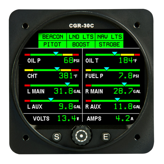
System Overview System Overview System Overview System Overview System Overview 1.1 System Description 1.1.1 CGR Display: 1.1.1 CGR Display: 1.1.1 CGR Display: 1.1.1 CGR Display: 1.1.1 CGR Display: 1.1.2 EDC-33P: 1.1.2 EDC-33P: 1.1.2 EDC-33P: 1.1.2 EDC-33P: 1.1.2 EDC-33P: 1.1.3 Probes, Transducers and Modules: 1.1.3 Probes, Transducers and Modules: 1.1.3 Probes, Transducers and Modules: 1.1.3 Probes, Transducers and Modules:... - Page 12 1.1.1 CGR Display: The CGR-30C (CGR) display measures 3.25" wide by 3.25" high by 4.36" deep and is designed to be mounted from behind the aircraft instrument panel into a standard 3 1/8" (3.125") hole. The 25-pin D-sub connector on the back of the CGR display is used to interface the CGR to the EDC-33P, Power &...
-
Page 13: Operational Overview
become semi-permanent. Everything else (CGR, EDC, Probes and Modules) can be easily discon- nected and removed. 1.2 Operational Overview: The CGR system measures a primary engine or aircraft function using a probe or transducer and dis- plays that function on the CGR screen using the following steps: A. -
Page 14: Hardware Installation
Hardware Installation Hardware Installation Hardware Installation Hardware Installation Hardware Installation 2.1 Important Information and Initial Checkout: 2.2 Review the "EDC Wiring Work Sheets:" 2.3 Verify You Have all the Probes, Modules, Transducers and Cables: 2.4 Install the CGR Display: 2.5 Install the Temperature Probes: 2.6 Install the Pressure Transducers: 2.7 Install the CO Detector, G-Sensor and/or Other Available CGR Options: 2.8 Install the Shunt (for Amps):... -
Page 15: Important Information And Initial Check Out
In most aircraft, installing the CGR-30C to the right of the Radio Stack would be acceptable. In some aircraft, the visual centerline falls to the right of the Attitude Indicator. -
Page 16: Review The "Edc Wiring Work Sheets
I. If the CGR-30C instrument is to replace an existing gauge or gauges in the aircraft, it is the installer’s responsibility to remove the duplicate gauges or components in accordance with FAA approved methods and procedures (see AC 43.13). J. An Installation Checklist is provided to assist the installation of the CGR system. It does not replace the instructions located in this manual. -
Page 17: Install The Temperature Probes
Important Notice: Install the CGR display in the panel using the supplied 6-32 x 1/4 screws. Longer screws will damage the display. Hand tighten the screws. Check the screws are tight against the panel before they bottom out. Driving the screws through the stops will damage the display. 2.5 Install the Temperature Probes: Install only the Temperature Probes applicable for your configuration. - Page 18 If a P-111, P-112 or P-114 TIT probe is to be installed, perform the steps outlined in the “TIT Probe Depth Adjustment Procedure” that comes with the TIT probe. NOTE: After the first 10 hours of operation, the hose clamp on the P-110 probe should be retightened. As the hose clamp is heated and cooled, it will become loose as it conforms to the exhaust stack.
-
Page 19: Install The Pressure Transducers
Mount the OAT Probe in an appropriate location on the aircraft, using the hardware supplied. The OAT Probe is sensitive to air temperature changes. For this reason, do not mount the OAT probe in the path of the cowl or engine exiting air (i.e., on the belly of the aircraft). Also, if the probe is mounted in the cowling area near a turbo or hot cylinder head, radiant heat may influence the probe temperature. - Page 20 Note: Many certified aircraft have a very small hole in the manifold pressure line to create airflow back to the intake manifold. This small flow of air keeps fuel from working its way into the manifold pressure gauge (or transducer), which can cause damage to the transducer over time. Note: The PT-30ABS can PRESS...
- Page 21 #2 Straight - AN816-2D #3 Straight - AN816-3D #4 Straight - AN816-4D 1/8 NPT Male 1/8 NPT 1/8 NPT Male Coupler #2 45' - MS20823-2D #3 45' - MS20823-3D #4 45' - MS20823-4D PT-100GA #2 90' - MS20822-2D AN910-1D Flare #3 90' - MS20822-3D #4 90' - MS20822-4D Vibration can cause the adapter to break, resulting in loss of engine oil.
-
Page 22: Install The Co Detector, G-Sensor And/Or Other Available Cgr Options
2.7 Install the CO Detector, G-Sensor and/or Other Available CGR Options: The CO Guardian Remote Mounted CO Detector, G-Sensor and other CGR options listed on EI’s price sheet are provided with their own installation instructions. These items should be installed and wired in accordance with the accompanying instructions. - Page 23 Figure 1: Figure 1: External Shunt Installed in the Battery Lead External Shunt Installed in the Battery Lead Figure 1: Figure 1: Figure 1: External Shunt Installed in the Battery Lead External Shunt Installed in the Battery Lead External Shunt Installed in the Battery Lead To Voltage Regulator Alterna- Master Switch...
-
Page 24: Install The Fuel Flow Transducer
easily, it should be covered. When mounting the shunt, use self-locking or safety-wired nuts. The signal wires from the shunt to the EDC must be fused a short distance after they leave the shunt. If this is a new installation, install two in-line one-amp fuses, one in each of the signal lines Aircraft Configuration Drawing # Fuel Flow Transducer Selection:... - Page 25 the fuel pump to the carburetor and one in the return line from the carburetor back to the fuel tank. Also, a Fuel Flow Differential Module (FFDM-1) will need to be installed. See drawings 1229932 and 1015941 on the following pages. Note: Note: Note: Insure the fuel flow transducer is appropriate for the horsepower of the engine...
- Page 26 . a t i o n s . a t i o n s . a t i o n s . Drawn By: Electronics International Inc. Electronics International Inc. Electronics International Inc. Electronics International Inc. Electronics International Inc.
- Page 27 (510) 483-8521 Fax: (916) 421-5719 FAX: (602) 899-0324 Fax: (510) 483-8524 5. Read the Installation Instructions for important installation considerations. Drawn By: Electronics International Inc. Electronics International Inc. Electronics International Inc. Electronics International Inc. Electronics International Inc. R.R. Approved By: Installation of a Fuel Flow Transducer on the Firewall and in R.R.
- Page 28 350 H.P. If the Transducer is mounted within 6" of an exhaust pipe, the Flow Transducer must be wrapped with Fire Sleeving. 5. Read the Installation Instructions for important installation considerations. Drawn By: Electronics International Inc. Electronics International Inc. Electronics International Inc. Electronics International Inc.
- Page 29 6" of an exhaust pipe, the Flow Transducer must be wrapped with Fire Sleeving. 5. Read the Installation Instructions for important installation considerations. Drawn By: Electronics International Inc. R.R. Approved By: Installation of a Fuel Flow Transducer suspended in the fuel R.R.
- Page 30 Electronics International. In this way the P-300M’s float arm and travel can be matched with the aircraft’s existing sender. Contact Electronics International for further information.
- Page 31 - Water logged floats. If you find inconsistent or inaccurate fuel level readings (due to a defective resistive fuel level sender), you must have the sender replaced. Inaccurate readings can lead to a dangerous situation. The CGR-30 depends on the fuel level sender for accurate fuel level information.
-
Page 32: Install The Voice Alarm Control Panel (Oem Only)
12" of the pilot's visual centerline. The lights will require 3/4" clearance behind the aircraft instrument panel. B. If the aircraft currently has Caution and Warning Lights for an existing CGR-30P or you are installing the CGR-30C and a CGR-30P, install the Mounting Plates as follows:... -
Page 33: Install The Usb-6A (Optional)
To CGR-30 Backlight annunciating the top instrument. 100uF, 35V C. The CGR-30C remote lights and mount- ing plate must be installed in a location where the placard will be readable in all lighting conditions. Installing the annunciators near an exiting lighting source or installing a post light are acceptable methods of compliance, other methods may also be acceptable. - Page 34 Install the EDC Wire Harnesses Install the EDC Wire Harnesses Install the EDC Wire Harnesses Install the EDC Wire Harnesses Install the EDC Wire Harnesses Route Wires Route Wires Route Wires Route Wires Route Wires 3.1 Attach the three EDC 37-pin Wire Harnesses to the EDC: 3.2 Connect the EDC Harness to the Temperature Probes: 3.3 Connect the EDC Harness to the Pressure Transducers: 3.4 Connect the EDC Harness to the Shunt:...
-
Page 35: Install The Edc-33P
If any additional modules are provided with the system, install them at this time using the instructions provide with the modules. 2.20 Install the EDC-33P: The EDC-33P (Engine Data Converter) converts all of the analog engine signals into serial data which is output to the CGR display via one wire (5V Serial). -
Page 36: Attach The Three Edc 37-Pin Wire Harnesses To The Edc
antenna wires. Also the interconnect wires should be routed away from the radio stack. 3.1 Attach the three EDC 37-pin Wire Harnesses to the EDC: Secure the connectors using the supplied mounting screws. 3.2 Connect the EDC Harness to the Temperature Probes: Route each of the temperature cables in the EDC harness to the appropriate temperature probe. -
Page 37: Connect The Edc Harness To The Existing Capacitive Fuel Level System
tion) and connect to the fuel flow transducer. When connecting to the Fuel Flow Transducer, leave some slack in the cable exiting the transducer to prevent future damage to the transducer. If the flow tranducer is hard mounted to a bracket, DO NOT connect the Black Gound Wire DO NOT connect the Black Gound Wire DO NOT connect the Black Gound Wire DO NOT connect the Black Gound Wire on the... -
Page 38: Fuel Level Sensors
fuel level input wires (for the number of tanks to be monitored) in the RFLM-4-x harness to the EDC Bottom Connector. Plug the wires into the appropriate resistive fuel level channels. The excessive wire can be cut and spliced, bundled and tie wrapped up or cut to length and new D-Sub pin installed (see the “Working with Connectors”... -
Page 39: Setup The Edc For A 4 Or 6-Cylinder Engine
EDC-33P To Aircraft Ground To the CGR/EDC 5-amp Circuit Breaker Top Connector CGR-30C Pin 37, Red Wire Pin 19 Black Wire 5V-Serial Output (pin 6) Splice Pin 18, White/Green Wire Note: The CGR-30P may... -
Page 40: Install The Cgr Wire Harness And Route The Wires
Install the CGR Wire Harness Route the Wires 4.1 Attach the CGR 25-pin D-sub Connector to the CGR: 4.2 Connect the EDC 5V-Serial Output Wire to the CGR 5V-Serial Input Wire: 4.3 Connect the CGR Harness to the Master Warning and Caution Lights: 4.4 Connect the CGR Harness to the Voice Alarm Control Panel (OEM Only): 4.5 Connect the CGR Harness to the Audio Panel (OEM Only): 4.6 Connect the CGR Harness to the Backlight Control Pot:... - Page 41 3.13 Connect the EDC Harness to Power and Ground: Route the power wire (Top Connector, pin 37, Red Wire) to the CGR/EDC 5-amp Circuit Breaker. Route the ground wire (Top Connector, pin 19, Black Wire) to the aircraft ground. WARNING: The power wire is RED and is connected to pin 37 on the EDC Top Connector. If aircraft power is connected to any pin on the EDC other than pin 37, damage to the EDC and any connected transducers may occur.
- Page 42 4.3 Connect the Master Warning and Caution Circuits: If the Warning and Caution Lights are installed, route the CGR Master Warning Out wire (White/Yellow, Pin 10) to the Master Warning (Red) Light (AL-1R) White/Yellow wire, cut the wires to length, install the appropriate connector and connect to the AL-1R.
-
Page 43: Mandatory System Setup And Checkout
Mandatory System Setup and Checkout 5.1 Power-On Checkout: 5.2 Perform all Steps listed in the "CGR-30C Setup Checklist": 5.3 Ground Run Checkout: 5.4 First Flight Checkout: 5.5 Read the "Warranty/Agreement" and the "Important Notice":... - Page 44 Note: Fuel Levels may not read properly until they have been calibrated. Note: Note: 5.2 Perform all Steps listed in the "CGR-30C Installation Checklist": A CGR-30C Installation Checklist is provided on blue tag board. Each step listed in this checklist must be completed before continuing with this installation.
- Page 45 5.3 Ground Run Checkout: Start the aircraft engine. Check that the values for each function displayed on the CGR are proper for "engine on" operation. Any problem with a specific function will be associated with a probe, cable or interconnect cable between the probe and the EDC for that function. If you have a problem with any of the following steps, see the Troubleshooting section of this manual.
-
Page 46: Installation Data
Installation Data 6.1 Instructions for Continued Airworthiness (ICA): 6.2 Airworthiness Limitations: 6.3 Installing a D-sub Pin onto a TC or Tin Copper Wire: CGR-30P Work Sheet, 25-pin D-sub Connector EDC Wiring Work Sheet, Top Connector (Back View) EDC Wiring Work Sheet, Middle Connector (Back View) EDC Wiring Work Sheet, Middle Connector (Back View) EDC Template... -
Page 47: Airworthiness Limitations
6.1 Instructions for Continued Airworthiness (ICA): The Instructions for Continued Airworthiness (ICA) are located in the Electronics International document 06211301 "CGR-30P & CGR-30C Instructions for Continued Airworthiness". If you need an additional copy of the CGR-30 ICA please visit: www.Buy-Ei.com or call (541) 318-6060. -
Page 48: Installing A D-Sub Pin Onto A Tc Or Tin Copper Wire
Insulation Installation: Bare Wire The CGR-30 system is to be installed in accordance with the current CGR-30 Installa- tion Instructions, AC 43.13 and any other appropriate FAA approved practices or E.I. D-sub Pin guidelines. These instructions along with FAA approved material insure the system will meet the requirements of the applicable TSOs once installed in an aircraft. - Page 49 Master Caution Out 23 AL-1Y (Yel) 3' Wht/Org Back Light Control In 2 To Dimming Rheostat Voice Control Ack 12 Voice Control +3.3V 13 Voice Control Off 25 (Not Avalable) Voice Warning Out + 11 Voice Warning Out - Electronics International inc.
- Page 50 + Signal In - Signal In +5V 28 Gnd 29 Pressure Ch5 + Signal In 11 - Signal In 10 +5V 30 Gnd 31 Pressure Ch6 + Signal In - Signal In 12 Do Not Use Do Not Use Electronics International inc.
- Page 51 + In (Yel) 16 Temp Ch 12 - In (Red) + In (Yel) 17 Temp Ch 13 - In (Red) + In (Yel) 18 Temp Ch 14 - In (Red) + In (Yel) 19 Temp Ch 15 - In (Red) Electronics International inc.
- Page 52 Open for 4-Cyl Extra Gnd 29 Extra Gnd 11 Extra Gnd + In (Yel) 12 Temp Ch 16 - In (Red) + In (Yel) 13 Temp Ch 17 - In (Red) Extra +5V Extra +5V Extra +5V 10 Electronics International inc.
- Page 53 3.710 3.160 3.160 0.550 0.550 2.350 0.000...
-
Page 54: Troubleshooting
Troubleshooting 7.1 CGR or EDC Problem: 7.2 Pressure Problem with one Function: 7.3 Temperature Problem on all Channels: 7.4 Temperature Problem with one Function: 7.5 RPM Problem: 7.6 Fuel Flow Problem: 7.7 Amp Problem: 7.8 Resistive Fuel Level Problem: 7.9 Capacitive Fuel Level Problem: 7.10 Voltage Problem:... - Page 55 will perform a good crimp but a 4 to 5 pound pull test must be performed. To install a D-sub pin onto a 20 ga. Tin Copper Wire, perform the following steps: A. Strip the insulation back 1/8.” Be careful not to knick the wire. B.
- Page 56 1. Problem: The Power or Ground wire is open or not connected properly. a) Action: Measure the voltage on the power and ground wires. Ohm the ground wire to ground. Look for a short. B. Symptom: B. Symptom: B. Symptom: “COM” is displayed for the digital value for most functions. The EDC is not communi- B.
- Page 57 tial voltage is 2.5 volts. The VI-221 is used to drop the voltage when measuring signals that switch from ground to bus voltage. a) Action: Measure the voltage on the EDC “+” and “-” inputs for the function with the problem.
-
Page 58: Rpm Problem
a) Action: Measure the voltage on each of the temperature channels. 7.4 Temperature Problem with one Function: Temperature is measured on the aircraft using a temperature probe with type K thermocouple (TC) wire. When the TC junction in the tip of the probe is heated, a small signal (approx. 23 micro volts per ‘F) is produced and monitored by the EDC on two extension wires. -
Page 59: Fuel Flow Problem
isolator is not used in series with this wire, damage to the RPM input on the EDC could occur. a) Action: Check that there is an Isolator(s) in line with the RPM signal wires from the EDC. If only one RPM channel is working, swap the wires to the EDC RPM channel and see if the problem follows the EDC channel or the wire to the P-lead. -
Page 60: Amp Problem
a) Action: Remove the Flow Transducer from the aircraft. Lightly blow into the transducer and check for the rotor to spin freely. Check for a Fuel Flow reading on the CGR when the rotor is spinning. If the rotor in the Flow Transducer does not spin, hold the transducer over white paper and tap at all angles. -
Page 61: Capacitive Fuel Level Problem
= full tank readings. 7.9 Capacitive Fuel Level Problem: Fuel can be measured in a fuel tank using a Capacitive Fuel Probe. The Electronics International P-300 Capacitive Fuel Probe connects to an IMC (Interface Module) located near the probe, and to the EDC through three wires. -
Page 62: Technical Data
Technical Data Specifications, Functions and Features... - Page 63 Specifications / Features 0226131 Rev. A: 07/25/2018 Models: CGR-30P, CGR-30C, EDC-33P and EDC-33T-XX CGR-30P and CGR-30C Weight: 1.1 Lbs. Environmental: Designed and Tested to TSO (DO-160G) Software: Designed and Documented to TSO (DO-178B, Level C) Minimum Performance Standards: TSO-C43c, TSO-C44c, TSO-C45b, TSO-C47a, TSO-C48a, TSO-49b and TSO-C55a.
- Page 64 Error Messages: “COM” - If communication is lost with the EDC, after 2 seconds all functions requiring signals from the EDC will display “COM” for its value. “A2D” - If the EDC sends an error message for a specific channel, the function associated with that channel (on the MVP) will display “A-D”...
- Page 65 Amps: Common Mode Input Resistance: > 10 M Ohms Diff. Input Resistance: 10K Ohms Differential Input: + 2.5V to -.2V Common Mode: +/- 90 Volt to ground Sensitivity: 9.537uV per count. Note: An FM-VA-MVP-xx module may be used to measure Voltage and Amps on any two temp channels.
- Page 66 Temperature: Input Range: 0 to 2.5 Volts Differential Input Impedance: 12.1K Ohms on each input to ground Sensitivity: 9.537uV per count. Notes: * Any Temp Channel may be used to measure any thermocouple probe or any device outputting a voltage. In this way many different types of function may be monitored through a temperature channel.
- Page 67 Capacitive Fuel Level: The resistive and capacitive inputs share channels. Only one input type should be used per channel. Input Trigger Level: 2.1 Volts Frequency Range: 0 to 15KHz. Input Impedance: 33.2K Ohms Sensitivity: 14 counts per Hz.. Notes: The Capacitive Fuel Level inputs may be used to monitor other functions. EDC-33T (Both RPM Channels): Input Trigger: +.39V / 0V (Hysteresis) Input Resistance: 20K ohms...
- Page 68 Appendix STC and AML...
Need help?
Do you have a question about the CGR-30C and is the answer not in the manual?
Questions and answers