Table of Contents
Advertisement
Quick Links
Download this manual
See also:
Operating Manual
WHITE-RODGERS
Operator: Save these instructions for future use!
FAILURE TO READ AND FOLLOW ALL INSTRUCTIONS CAREFULLY
BEFORE INSTALLING OR OPERATING THIS CONTROL COULD CAUSE
PERSONAL INJURY AND/OR PROPERTY DAMAGE.
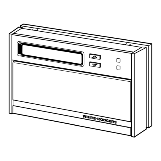
This wall-mounted, low voltage thermostat maintains
room temperature by controlling the operation of multi-
stage systems. Use this thermostat for applications re-
quiring up to three stages of heat and up to two stages of
cool. Indicator lights show the system status. The user
may program up to four time/temperature settings per 24
hour period. The thermostat stores settings for a five-day
(weekday) program and a two-day (weekend) program.
The thermostat will store both heating and cooling pro-
grams simultaneously. A 9 volt Energizer
maintain the stored program for approximately one week,
if incoming power should fail. If power failure is extensive
and the program is lost, after power restoration, the
thermostat will automatically maintain a factory
preprogrammed heating temperature of 64°F or a cooling
temperature of 82°F.
If in doubt about whether your wiring is millivolt, line, or low
voltage, have it inspected by a qualified heating and air
conditioning contractor, electrician, or someone familiar
with basic electricity and wiring.
Do not exceed the specification ratings.
CONTENTS
Description .......................................................... 1
Precautions ......................................................... 1
Specifications ...................................................... 2
Installation ........................................................... 2
Operation ............................................................ 6
Troubleshooting
WHITE-RODGERS DIVISION
EMERSON ELECTRIC CO.
9797 REAVIS ROAD
ST. LOUIS, MISSOURI 63123-5398
Multi-stage Electronic Digital Thermostat
INSTALLATION INSTRUCTIONS
®
battery will
All wiring must conform to local and national electrical
codes and ordinances.
This control is a precision instrument, and should be
handled carefully. Rough handling or distorting compo-
nents could cause the control to malfunction.
To prevent electrical shock and/or equipment
damage, disconnect electric power to system at
main fuse or circuit breaker box until installation
is complete.
Do not use on circuits exceeding specified volt-
age. Higher voltage will damage control and
could cause shock or fire hazard.
Do not short out terminals on gas valve or pri-
mary control to test. Short or incorrect wiring will
burn out thermostat and could cause personal
injury and/or property damage.
Printed in U.S.A.
1F91W-71
DESCRIPTION
PRECAUTIONS
CAUTION
!
WARNING
!
PART NO. 37-5519A
9522
Advertisement
Table of Contents

Related Manuals for White Rodgers 1F91W-71


Summary of Contents for White Rodgers 1F91W-71
-
Page 1: Table Of Contents
1F91W-71 WHITE-RODGERS Multi-stage Electronic Digital Thermostat INSTALLATION INSTRUCTIONS Operator: Save these instructions for future use! FAILURE TO READ AND FOLLOW ALL INSTRUCTIONS CAREFULLY BEFORE INSTALLING OR OPERATING THIS CONTROL COULD CAUSE PERSONAL INJURY AND/OR PROPERTY DAMAGE. DESCRIPTION This wall-mounted, low voltage thermostat maintains room temperature by controlling the operation of multi- stage systems. -
Page 2: Specifications
SPECIFICATIONS THIS CONTROL IS DESIGNED FOR USE WHERE BOTH SIDES OF THE TRANSFORMER ARE PRESENT TO THE THERMOSTAT (both the hot and common sides of the 24 VAC end of the transformer.) ELECTRICAL DATA THERMAL DATA Electrical Rating: Setpoint Temperature Range: 20 to 30 VAC 50/60 Hz. -
Page 3: Replacement Installation
REPLACEMENT INSTALLATION REMOVE OLD THERMOSTAT 1. Shut off electricity at the main fuse box until installa- tion is complete. Verify power is off with a voltmeter. 2. Remove the front cover of the old thermostat. With wires still attached, remove wall plate from the wall. 3. - Page 4 2. Connect wires beneath terminal screws on subbase Expansion plugs using wiring schematic (see figs. 3 through 6). Connect wires under 3. Place subbase over hole in wall and mark mounting terminal screws hole locations on wall using subbase as a template. 4.
- Page 5 NOTE IF SAFETY CIRCUITS ARE IN ONLY ONE OF THE SYSTEMS, REMOVE THE TRANSFORMER OF THE SYSTEM WITH NO SAFETY CIRCUITS. Thermostat Control Circuit THERMOSTAT SYSTEM Changeover Compressor Heat Heat CUT AND Energized Contactor Relay Relay TAPE OFF! In Heat Stage 2 Stage 1 Stage 3...
-
Page 6: Attach Thermostat To Subbase
tors and the plastic snaps lock into place (see fig. 7). Be ATTACH THERMOSTAT TO SUBBASE gentle when attaching thermostat. If the thermostat does not seem to be attaching to the subbase easily, IT IS RECOMMENDED THAT YOU SET OPTION make sure that the connector pins and plastic snaps are SWITCHES TO DESIRED POSITION BEFORE ATTACH- properly aligned, and that excess wire is pushed into the... -
Page 7: Check Thermostat Operation
CHECK THERMOSTAT OPERATION After heating and cooling system have been checked and are running properly, determine if automatic changeover is desired (see SYSTEM CONFIGURATION). FAN OPERATION Refer to the OPERATION GUIDE if you need additional 1. Turn on power to the system. If the heat source has information on thermostat operation. - Page 8 If you need further information about this product, please write to White-Rodgers Division, Emerson Electric Co. 9797 Reavis Road St. Louis, MO 63123-5398 Attention: Technical Service Department...
Need help?
Do you have a question about the 1F91W-71 and is the answer not in the manual?
Questions and answers
what terminals do i hook up my red white green and blue wires to on my 1f91-71 thermostat?