Otodynamics Otoport OAE+ABR User Manual
Hide thumbs
Also See for Otoport OAE+ABR:
- User manual (297 pages) ,
- User manual (228 pages) ,
- User manual (206 pages)

Subscribe to Our Youtube Channel
Related Manuals for Otodynamics Otoport OAE+ABR


Summary of Contents for Otodynamics Otoport OAE+ABR
- Page 1 Otoport User Manual for Otoport Lite model Otoport OAE+ABR Otoport Lite model Issue 4...
- Page 2 No part of this publication may be copied by any means, translated or distributed to third parties without the express written permission of Otodynamics Ltd. Copyright © 2017 Otodynamics Ltd. All Rights Reserved. Otodynamics Ltd 30-38 Beaconsfield Rd Hatfield Herts AL10 8BB UK...
-
Page 3: Table Of Contents
General guidance General use precautions Types of otoacoustic emissions OAEs and screening Auditory Brainstem Response Equipment identification Supplied only in Otoport OAE+ABR kit: Supplied only in Otoport Lite kit: Supplied in both kits: Optional accessories Otoport controls, indicators and connections Scanner... - Page 4 CHAPTER ONE Introduction...
- Page 5 Otoport OAE+ABR User Manual for Otoport Lite model Switching On Switch on screen Logo screen Login Main menu Test preparation General checks before testing Environment checks for ABR Tip selection and probe fitting Electrode fitting Test troubleshooting OAE test problems...
- Page 6 CHAPTER ONE Introduction...
- Page 7 Otoport OAE+ABR User Manual for Otoport Lite model Worklist Adding Patients Testing from the Worklist Editing details Deleting patients Records Patient list 10.1 Configuration Configuration menu 11.1 Quality tests 11.2 Test settings 11.3 Date and time 11.4 System 11.5 Users 11.6...
- Page 8 16.3 Care of the Otoport Use of the Otoport and cleaning 17.1 Power Battery life 18.1 Initial charge 18.2 Standby 18.3 Battery charge 18.4 Charging the Otoport 18.5 Conditioning the Otoport battery 18.6 Additional battery care 18.7 Otoport OAE+ABR 18.8...
- Page 9 Training Obtaining service Calibration Mode of operation TEOAE model 23.1 DPOAE model 23.2 ABR test 23.3 Technical specifications Otoport 24.1 Electromagnetic Compatibility: Otoport 24.2 Electromagnetic Compatibility: Otoport OAE+ABR 24.3 EN60645-3 conformance notes 24.4 ABR Module 24.5 Symbol explanations 24.6 Index...
-
Page 10: Introduction
CHAPTER ONE Introduction Introduction This manual provides instructions for use for two compact, handheld instruments, the Otoport OAE+ABR (Otoport Lite model) and the Otoport Lite OAE system. Intended Use This Otodynamics Otoport/Otocheck OAE+ABR device is indicated for use when there is a requirement to screen for hearing disorders by objective and non-invasive means. -
Page 11: General Guidance
Configuration, section Pass criteria). OAE screening functions 11.3.4 include Otodynamics classic Quickscreen TEOAE technology and Rapid DPOAE technology (depending on the model). The device can be used in a wide range of different environments for example in the well-baby nursery, the NICU, a doctor’s office, an audiology clinic, the outpatient clinic or in the home. -
Page 12: General Use Precautions
CHAPTER ONE Introduction General use precautions TRAINING REQUIRED The Otoport pass criteria are set in the Configuration area (see chapter Configuration). It is the responsibility of the user to ensure that the pass criteria set meet their requirements. Measuring OAEs and ABRs requires that the ear is exposed to sound. Whilst the level of this exposure is harmless under normal test conditions, it is not recommended that tests be allowed to continue indefinitely even if there is no result. - Page 13 Otoport OAE+ABR User Manual for Otoport Lite model Visually inspect the coupler tubes before use. A blocked sound delivery tube may prevent the Otoport from achieving its target stimulation level and so prevent testing. It may also attenuate certain frequencies and limit the number of pass bands.
-
Page 14: Types Of Otoacoustic Emissions
CHAPTER ONE Introduction Types of otoacoustic emissions Otoacoustic emissions are sounds which can be recorded in the ear canals of functionally normal ears. This Otoport can make two types of OAE measurements: Transient Evoked OAEs (TEOAEs) and Distortion Product OAEs (DPOAEs). The difference between the measurements is largely in the means used to generate and measure the emission, rather than in the source of the emission itself. -
Page 15: Oaes And Screening
Otoport OAE+ABR User Manual for Otoport Lite model OAEs and screening OAE testing is commonly used as the primary hearing screen in newborns with no known hearing loss risk factors. Failure to show a strong OAE indicates that further testing or observation is necessary. -
Page 16: Auditory Brainstem Response
CHAPTER ONE CHAPTER ONE Introduction Introduction Auditory Brainstem Response Auditory Brainstem Response (ABR) is an electrophysiological response that measures the auditory system’s response to sound. Three voltage sensors (electrodes) are placed on the patient and a sound probe is placed in the test ear. -
Page 17: Equipment Identification
Otoport OAE+ABR User Manual for Otoport Lite model Equipment identification Supplied only in Otoport OAE+ABR kit: LTC-ST+ABR (TEOAE model) or LTC-SD+ABR (DPOAE model) Otoport Lite OAE+ABR REF ABR-EC1 Electrode cables - 1m REF ABR-EC2 Electrode cables - 2m REF ABR-SK... -
Page 18: Supplied Only In Otoport Lite Kit
Equipment identification REF ABR-CAV Probe cavity and ABR cable tester REF ABR-INF Infection control sleeve for Otoport OAE+ABR unit only Shown fitted REF ABR-CAS Equipment case for Otoport OAE+ABR kit Supplied only in Otoport Lite kit: REF LTC-ST or LTC-SD... -
Page 19: Supplied In Both Kits
Otoport OAE+ABR User Manual for Otoport Lite model REF OAE-CAV Probe test cavity Supplied in both kits: REF PR-UGS UGS TEOAE probe Supplied with TEOAE model REF PR-UGD UGD DPOAE probe Supplied with DPOAE model REF PR-POUCH Drawstring probe pouch... - Page 20 CHAPTER TWO Equipment identification REF TPC TPC probe coupler tubes x 5 Supplied with TEOAE probe Re-order quantity: 10 or 100 REF DPC DPC probe coupler tubes x 5 Supplied with DPOAE probe Re-order quantity: 10 or 100 REF BGS BGS probe body and lid x 1 Supplied with TEOAE probe Re-order quantity: 10...
- Page 21 Otoport OAE+ABR User Manual for Otoport Lite model REF OP-CHG Charger and mains lead REF OP-CAB PC downoad cable REF OTOLINK Otolink software CD REF OP-INF Infection control sleeve for Otoport only Shown fitted Documentation pack Includes instrument and software...
-
Page 22: Optional Accessories
For use with Otoport Lite REF OMP-R Otoport printer Wired and wireless models available for Otoport Lite Wireless model available for Otoport OAE+ABR REF OPP-CAS Large equipment case For use with Otoport Lite, with additional compartment for printer REF ABR-CUP... - Page 23 Otoport OAE+ABR User Manual for Otoport Lite model Printer accessories and consumables 2.4.1 REF OMP-CAB-R Otoport printer cable For use with Otoport OAE device (not for use with ABR) REF OMP-CHG-R Otoport printer charger REF OMP-PAP-R Otoport printer paper rolls...
-
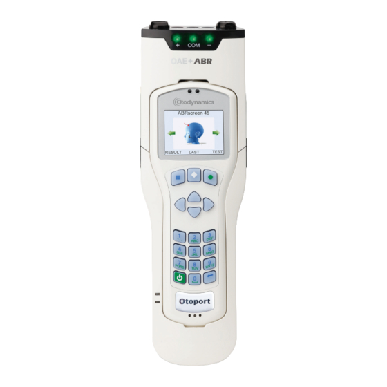
Page 24: Otoport Controls, Indicators And Connections
CHAPTER TWO Equipment identification Otoport controls, indicators and connections Probe socket Stimulus OK (S) and Noise OK (N) indicators Display screen Menu selection keys Up/down/left/right navigation keys Data entry keypad On/Off power key Charging status indicators Speaker Charger and PC cable socket... -
Page 25: Scanner
Otoport OAE+ABR User Manual for Otoport Lite model Scanner Barcode/RFID scanner (not included as standard) Grip strip... -
Page 26: Oae Labelling
CHAPTER TWO Equipment identification OAE labelling Symbols 2.7.1 The label uses one or more of the following symbols: Caution Refer to user manual Class II electrical protection (double insulated) Type BF applied part Bluetooth ® enabled RFID enabled... - Page 27 Otoport OAE+ABR User Manual for Otoport Lite model Manufacturer Serial Number The Otoport serial number comprises model code (LTC or LDC), year and month of manufacture (yymm) and unique manufacture ID (xxxx). The complete serial number is therefore LXX/yymmxxxx. Certification or regulatory marks 2.7.2...
-
Page 28: Otoport Oae+Abr Controls, Indicators And Connections
CHAPTER TWO Equipment identification Otoport OAE+ABR controls, indicators and connections Probe sockets and electrode sockets Impedance check indicator LEDs Quick-release clips Otoport unit Otoport controls and keypad ‘USB/PSU’ connected’ and ‘battery charging’ indicator LEDs Charger / PC cable socket... -
Page 29: Abr Labelling
Otoport OAE+ABR User Manual for Otoport Lite model ABR labelling Symbols 2.9.1 The label uses the following symbols: Bluetooth enabled Caution Refer to user manual Class II electrical protection (double insulated) Type BF applied part Manufacturer Serial Number... - Page 30 The fields in the serial number are made up of the following parts: (01) Company prefix: Otodynamics, Item reference: Otoport Lite OAE+ABR (11) Production date: 31st January 2015 (21)
-
Page 31: Getting Started
Otoport OAE+ABR User Manual for Otoport Lite model Getting started If you have purchased the ABR Module as an upgrade to your Otoport, you will first need to assemble the equipment, as follows. Assembling the ABR Module with an Otoport The ABR Module is designed to be fitted as a ‘sleeve’... - Page 32 CHAPTER THREE Getting started Slightly tilt the upper section back (see diagram on label inside Module). 3.1.3 Do NOT tilt it forwards and do NOT force it back. Carefully insert the Otoport into the sleeve and slide it down until the 3.1.4 connector at the bottom of the sleeve is inserted into the port at the bottom of the Otoport...
- Page 33 Otoport OAE+ABR User Manual for Otoport Lite model Do NOT insert the Otoport into the top of the module first, or insert into the bottom of the sleeve at an angle, as this may cause damage. Lower the sleeve until the connector at the top of the ABR Module is 3.1.6...
-
Page 34: Removing The Otoport From The Abr Module
Otoport OAE+ABR with non-removable module If you have purchased an Otoport OAE+ABR with a permanently fitted sleeve, sometimes referred to as ‘locked’, it is not possible to remove the Otoport from the module. The clips on the side of the locked module are flat. -
Page 35: Connecting Probes And Electrodes
Otoport OAE+ABR User Manual for Otoport Lite model Connecting probes and electrodes The connections panel for probes and electrodes is found at the top end of the module. Connecting the probe 3.4.1 Follow instructions for connecting the probe to the Otoport in section... - Page 36 CHAPTER THREE Getting started Connecting the electrodes 3.4.2 The Otoport OAE+ABR is supplied with an electrode cable loom featuring snap stud connectors for electrode attachment. Alternatively, any wired electrodes that are terminated with 1.5mm ‘Touchproof’ DIN 42-802 connectors may be used.
-
Page 37: Initial Charge
Otoport OAE+ABR User Manual for Otoport Lite model Initial charge Before using the equipment for the first time, fully charge the unit. See chapter Power for details. Using the Otoport keys and keypad Control keys 3.6.1 The keys directly below the screen marked with a square, a diamond or a circle enable you to execute the functions offered on the screens. - Page 38 CHAPTER THREE Getting started Entering characters 3.6.3 Character entry is similar to a mobile phone where numbered keys can be pressed sequentially to select the required character. The order of the characters is dependent on context. For example when used to enter: Patient ID Numbers are presented first then capitals, e.g.
- Page 39 Otoport OAE+ABR User Manual for Otoport Lite model Entering dates 3.6.5 A right arrow symbol is shown at the end of a date field. When the field is highlighted, press the right arrow key to access the calendar pop-up table. The day will be highlighted first and can be altered using the up and down arrow keys.
- Page 40 CHAPTER THREE Getting started Deleting characters 3.6.7 The bottom right hand key shown above is used as a delete key. If the cursor is at the end of a row of characters, press this key to delete the last character. Left and right arrow keys can be used to scroll back through the text.
-
Page 41: Connecting The Probe To The Otoport
Otoport OAE+ABR User Manual for Otoport Lite model Connecting the probe to the Otoport TRAINING REQUIRED Prior to the testing session, connect the probe to the Otoport. The probe plug contains a ‘key’ that must be aligned with the ‘keyway’ in the probe socket on the Otoport. -
Page 42: Disconnecting The Probe From The Otoport
CHAPTER THREE Getting started Push the probe into the socket until it hits the end stop. DO NOT force the probe in further. Probe in socket Screw up the knurled sleeve in a clockwise direction until finger tight. Turn knurled sleeve clockwise Disconnecting the probe from the Otoport To disconnect the probe, unscrew the knurled sleeve in an anticlockwise... - Page 43 Otoport OAE+ABR User Manual for Otoport Lite model Important Note: Remove probe Do NOT attempt to screw or unscrew the probe by holding the main probe body (smooth chrome section). This will result in damage to the probe and will invalidate the probe warranty.
-
Page 44: Switching On
CHAPTER FOUR Switching on Switching On Switch on screen To switch on the Otoport press the green On/Off power key found at the bottom left of the keypad. The display screen will show Switch Unit On?. Select Yes to confirm Otoport switch on, or No to turn the unit off again. If Yes or No are not selected within two seconds of pressing the on/off power key, the device will automatically turn off. -
Page 45: Logo Screen
User Manual for Otoport Lite model Logo screen Following switch on, an Otodynamics logo animation is displayed whilst the device performs a series of hardware system checks. In the unlikely event of any of the systems checks failing, an error message will be displayed Hardware fault messages for details). -
Page 46: Login
CHAPTER FOUR Switching on Login If Login is on (see section ) the login screen will be displayed and the 11.6 user will be required to enter a name and password. Use the left and right arrow keys to choose the correct user name from the choice bar. -
Page 47: Main Menu
Otoport OAE+ABR User Manual for Otoport Lite model Main menu You are then presented with the main menu screen. From here you can view the Result of the last test, select the Last patient tested or perform a Test. The heading on the screen indicates whether the Otoport is a TEOAE or DPOAE model. -
Page 48: Test Preparation
CHAPTER FIVE Test preparation Test preparation TRAINING REQUIRED Good preparation for testing will improve test results and make testing more efficient and less stressful for the baby, parents and tester. General checks before testing Ensure the Otoport is charged (see chapter Power for information). -
Page 49: Tip Selection And Probe Fitting
Otoport OAE+ABR User Manual for Otoport Lite model Tip selection and probe fitting Appropriate tip selection and good probe fit are essential to ensure successful recordings. A good probe fit will help to block out external noise and enhance the OAE signal. The Otoport is supplied with a full range of tips to fit all ear canal sizes. - Page 50 CHAPTER FIVE Test preparation Fitting for newborns using ear cups 5.3.2 When using ear cups, there are two probe tips that you can use for the best fit of the probe to the ear cup. These are the T7M tip for TE probes and the R7M tip for DP probes;...
-
Page 51: Electrode Fitting
Otoport OAE+ABR User Manual for Otoport Lite model Electrode fitting Skin preparation 5.4.1 The skin at the electrode sites must be prepared to ensure that the impedance is low enough for a good recording. Use electrode skin preparation pads/tape, exfoliating pads (e.g. Dry Prep), or a swab coated with Nuprep™... - Page 52 CHAPTER FIVE Test preparation Placement (montage) 5.4.2 Electrodes are placed at three sites: the high forehead, the nape of the neck, and a reference (common) electrode on either the shoulder or cheek. In all locations avoid hair when possible. When using wet gel electrodes the sticky area around the central gel should be pressed to the skin –...
- Page 53 Otoport OAE+ABR User Manual for Otoport Lite model If using snap stud electrodes, now connect the electrode cables to the sensors. Connect the red cable to the high forehead, the white cable to the nape of the neck and the black cable to the back of the shoulder.
-
Page 54: Test Troubleshooting
CHAPTER SIX Test troubleshooting Test troubleshooting OAE test problems The most frequent cause of unsuccessful OAE recordings is failure to fit the probe correctly, so that it is deep enough in the ear canal. The presence of fluid and debris in the ear canal or middle ear will also inhibit recordings. If a pass result is not obtained, remove the probe and inspect the probe tip. -
Page 55: Abr Test Problems
Otoport OAE+ABR User Manual for Otoport Lite model ABR test problems Impedance values are too high and the test will not run 6.2.1 Solutions: Wait for about two minutes. During this time the electrodes may connect better to the skin and, therefore, reduce the impedance values. - Page 56 CHAPTER SIX Test troubleshooting 5. Touch each electrode to identify which is causing the problem, try: • holding the skin around the electrode taut • maintaining light pressure on the electrode • gently stroking the baby’s head • repositioning the baby’s head High environment electrical noise 6.2.3 Audible noise in the room as well as interference from other electrical...
-
Page 57: Oae Test Procedure
Otoport OAE+ABR User Manual for Otoport Lite model OAE test procedure TRAINING REQUIRED A Test may be started by selecting Test or Last from the main menu screen, from the Worklist or by selecting Test from the Patient details screen, in the Records area. -
Page 58: Checkfit
CHAPTER SEVEN OAE test procedure Checkfit Checkfit display 7.1.1 It is important to perform a test in the appropriate conditions. The Checkfit screen allows a user to assess the testing environment. Conditions such as high ambient noise, poor fit of the probe in the ear (including leaks) and blocked probes can be detected before starting the test. - Page 59 Otoport OAE+ABR User Manual for Otoport Lite model If the position of the Fit Size Indicator corresponds with the age of the patient and Checkfit is displayed on the top of the screen then the probe fit and the test conditions are adequate for testing. The Stimulus and Noise OK indicators (above the screen) should also be illuminated.
-
Page 60: Te Test (Teoae Model)
CHAPTER SEVEN OAE test procedure The following table describes what Highlighted Message will appear if more than one condition is met. Consistent Stimulus Out Stimulus Highlighted High Noise of Range Ringing Message Checkfit Noisy Check Probe Fit Ringing Check Probe Fit Ringing Check Probe Fit Check Probe Fit... - Page 61 Stim out of range will be displayed. The user then has the option to Continue or Cancel the test. In these circumstances Otodynamics recommends that the test is cancelled. Efforts should then be made to improve the probe fit, check the probe coupler tubes are clear and improve the test environment.
- Page 62 CHAPTER SEVEN OAE test procedure Test screens 7.2.2 The test screen display depends upon the display option set in the Configuration menu (see chapter Configuration). The default display is a simple One circle view. One circle In the One circle display a single circle shows progress towards meeting the pass criteria.
- Page 63 Otoport OAE+ABR User Manual for Otoport Lite model Noise level indicator A Noise Level Indicator is shown on the right of the screen. The bar moves in response to changes in noise. For good testing conditions the bar should be consistently below the Noise Reject Level, which is represented by the horizontal line across the Noise Level Indicator.
- Page 64 CHAPTER SEVEN OAE test procedure Test stop reasons 7.2.3 There are four possible ways in which a test can stop: AutoStop, Maximum NLo Sweeps, Test Timeout and Manual End. When the test stops the data collected is assessed and a result given as a pop-up graphic and then written highlighted at the top of the test screen.
- Page 65 Otoport OAE+ABR User Manual for Otoport Lite model Pausing and cancelling the test You may wish to pause a test for instance during periods of noise. When the test is paused, it is possible to cancel the test and discard the data.
- Page 66 CHAPTER SEVEN OAE test procedure Test results The following table lists all possible test results with the associated result graphic and gives an explanation of the circumstances under which each result would be shown. Test Result Description TEOAE Pass The data collected has met the criteria set. The optimum test setting will depend on your application (see Test settings)
-
Page 67: Dp Test (Dpoae Model)
Otoport OAE+ABR User Manual for Otoport Lite model DP test (DPOAE model) During testing the Otoport plays pairs of tones at different frequencies into the ear and records the response. The OAE signal is very small and difficult to distinguish from the noise made by other sounds in the room and by the patient. - Page 68 CHAPTER SEVEN OAE test procedure If calibration continues to fail, regardless of the position of the probe in the ear, it is likely that the probe has become blocked. In this case, inspect the probe coupler tubes and replace if necessary, then run Probe tests (see chapter ) to test the probe and Otoport performance.
- Page 69 Otoport OAE+ABR User Manual for Otoport Lite model It is the responsibility of the user to ensure that the pass criteria set meet their requirements. Noise level indicator A Noise Level Indicator is shown on the right of the screen. The bar moves in response to changes in noise.
- Page 70 CHAPTER SEVEN OAE test procedure Manual end Selecting End at any time will stop the test. Pausing and cancelling the test You may wish to pause a test for instance during periods of noise. When the test is paused, it is possible to cancel the test and discard the data. Select Cancel to pause the test.
- Page 71 Otoport OAE+ABR User Manual for Otoport Lite model Test results 7.3.4 The following table lists all possible test results with the associated result graphic and gives an explanation of the circumstances under which each result would be shown. Test Result...
-
Page 72: Quick Save Option
CHAPTER SEVEN OAE test procedure Quick Save option The options available from the test result screen depend on the Quick Save option (see chapter Configuration) Quick Save On 7.4.1 If Quick Save is On, select Left to save the test to the left ear, or Right to save to the right ear. - Page 73 Otoport OAE+ABR User Manual for Otoport Lite model After the save is confirmed, the option to retest the same patient will be displayed. Select Yes to run another test on the same patient or No to return to the main menu.
-
Page 74: Review
CHAPTER SEVEN OAE test procedure Review The review screen shows the result of the test. If the display is set to One Circle (TE model only), a large checkmark is displayed to indicate a pass. If the display is set to Circles, small circles appear with a checkmark in each band that met pass criteria. -
Page 75: Save
Otoport OAE+ABR User Manual for Otoport Lite model Save The Enter details screen is shown. The patient ID is filled with an automatically generated ID. The Name field displays Auto. The user may either save these details or overwrite them with alternative patient’s details. - Page 76 CHAPTER SEVEN OAE test procedure Select left or right ear 7.6.1 The Select Ear screen represents the patient facing you. By defaulting to a No Ear Choice the Select Ear screen forces the user to choose an ear before the test can be saved. Press the right control key or the right arrow to select the Left Ear or press the left control key or the left arrow key to select the Right Ear.
-
Page 77: Final Review
Otoport OAE+ABR User Manual for Otoport Lite model The pop up message Last Test Saved to Left/Right Ear. Save Test to Left/Right Ear Again? may appear on Save if the patient’s previous test was saved to the same ear. Select Yes to accept the current ear choice or No to return to the Select Ear screen. -
Page 78: Last
CHAPTER SEVEN OAE test procedure Last After one ear has been tested, further tests can be added to the same patient record by selecting Last from the main menu. Patient details can be amended and tests printed using this function. From the Main Menu select Last. - Page 79 Otoport OAE+ABR User Manual for Otoport Lite model The details stored can be edited by using the up/down keys to locate the correct field and then entering the new data using the keypad. All fields except Location, Facility and NICU can be edited. When an edit has been made the screen will change: If you are happy with the changes you have made select Save.
-
Page 80: Result
CHAPTER SEVEN OAE test procedure Result Select Result to review the tests results for the current patient. Select displays the detailed result for this test. Select Print to print this test result. -
Page 81: Abr Test
Otoport OAE+ABR User Manual for Otoport Lite model ABR test TRAINING REQUIRED Use the left or right arrow key to choose your ABR test screen. Note: The ABR test can operate in different Modes. The following text refers to Screening Mode, where Autostart is ON. See section in the Configuration chapter for Mode configuration 11.3.4... -
Page 82: Impedance Check
CHAPTER EIGHT ABR test procedure Impedance check The Otoport checks the quality of the connection between the skin and each of the three electrodes. This takes 2-3 seconds. A low impedance provides a good connection. Achieving optimum electrode impedance requires practice and experience. The Otoport also checks the noise levels, marked TN and PN on the screen. - Page 83 Otoport OAE+ABR User Manual for Otoport Lite model If the test still does not start automatically, observe the two noise bars TN (EEG Noise), and PN (Powerline Noise). They may be high. For advice on how to reduce the noise see section ABR test problems.
- Page 84 CHAPTER EIGHT ABR test procedure Further advice on ... Otoport impedance measurements The impedance of each electrode, Forehead (+ve), Nape (-ve) and Common are shown in the Impedance Check panel. Green circles are displayed for all impedance values where testing is possible.
- Page 85 Otoport OAE+ABR User Manual for Otoport Lite model Further advice on ... Electrical noise indicators The bars on the left of the screen indicate the electrical noise levels. The lower the test noise the more rapidly an ABR response will be detected.
-
Page 86: Checkfit
CHAPTER EIGHT ABR test procedure Checkfit The test stimulus in ABR tests can be provided either by inserting the probe into the ear, as for OAE testing, or by applying an ear cup to the ear and inserting the probe into the ear cup. Ear cups can be particularly useful in neonates with very small ear canals where a secure probe fit is not possible. -
Page 87: Abr Test
Otoport OAE+ABR User Manual for Otoport Lite model If Checkfit is selected, the device will go back into Checkfit and re-check whether ear cups are being used or not. If Yes is selected, the device will go into ear cup Checkfit as shown below. - Page 88 CHAPTER EIGHT ABR test procedure The circle indicates the probability that an ABR response is present. The circle is filled when there is 99% confidence that a response is present. NLO is an indication of the amount of data which has been collected with the noise lower than the noise reject level.
- Page 89 Otoport OAE+ABR User Manual for Otoport Lite model NHi/NLo NLo shows the number of sweeps accepted into the average. NHi shows the number of sweeps rejected due to high electrical noise levels. Accepted Shows the number of sweeps accepted into the average.
- Page 90 CHAPTER EIGHT ABR test procedure Impedance monitoring 8.4.3 During the test, if progress towards ABR detection is slow, the impedance levels are automatically checked in the background. • If impedances are low, the test will continue. • If impedances are high, the test is paused and the ‘Impedance Check’ screen will be displayed.
- Page 91 Otoport OAE+ABR User Manual for Otoport Lite model Test stop reasons 8.4.6 There are five possible ways in which a test can stop, described below. When the test stops the data collected is assessed. The result is given as a pop-up graphic and written highlighted at the top of the test screen. The Otoport will beep once if a test has stopped with an ABR Pass result and will beep twice if the test has stopped with any other result.
- Page 92 CHAPTER EIGHT ABR test procedure Test timeout If a test has not met the set pass criteria then the test will stop after 10240 sweeps have been collected, or after 10 minutes. Noise target reached If the residual noise in the averaged test (ABR Noise) becomes so low that any ABR present would already have been detected, then further testing is redundant, so the test is ended.
- Page 93 Otoport OAE+ABR User Manual for Otoport Lite model Poor Probe Fit The last stimulus level recorded changed from that recorded at the start of the test by >3dB, or the last acoustic noise level recorded was high. Stopped Too Soon...
-
Page 94: Worklist
CHAPTER NINE Worklist Worklist The Worklist allows details for multiple patients to be entered into the Otoport prior to testing. This eliminates the need for data entry while with the patient, allowing for faster, more flexible testing. The Worklist is On by default but can be switched Off in the Config area (see chapter Access the Worklist by using the left or right navigation keys from the main menu. -
Page 95: Testing From The Worklist
Otoport OAE+ABR User Manual for Otoport Lite model When details are complete, select Save to save the details to the Worklist, Test to run a test on this patient, or Back to discard these patient details. Up to 50 patients may be added to the Worklist. -
Page 96: Deleting Patients
CHAPTER NINE Worklist Deleting patients Scroll to the required patient. Select Delete to remove. Select Yes to delete the selected patient from the Worklist. Select All to delete all of the patients from the Worklist. Select No to return to the Worklist without deleting any patient details. -
Page 97: Records
Otoport OAE+ABR User Manual for Otoport Lite model Records The Records section allows the user to see the Results of previous tests and to view the Details of patients previously tested. Records may be erased from the Memory Status screen accessed from... -
Page 98: Patient List
CHAPTER TEN Records Patient list 10.1 The Patient list displays the ID/Notes field and Name of each patient. The up and down arrow indicators to the left of the Patient list show that there are other patient records not currently visible on screen. At the top of the screen, the total number of patients in the list and the position of the current patient in the list are displayed: 12/34 indicates that the current patient is twelfth in a list of 34 patients. - Page 99 Otoport OAE+ABR User Manual for Otoport Lite model Details 10.1.1 The Patient Details screen allows the user to see the ID/Notes field, Name, Date of Birth (DOB) and Gender stored for a particular patient. Selecting Test from this screen starts a new test, the result of which will be saved with the records of the selected patient.
- Page 100 CHAPTER TEN Records Test summary 10.1.2 TRAINING REQUIRED The test summary gives an overview of the test result including ½ octave band passes and total OAE signal level. The diagrams below illustrate the features of a test summary screen. The number of tests currently saved to the patient is displayed in the top right of the screen.
- Page 101 Otoport OAE+ABR User Manual for Otoport Lite model TEOAE test summary screen No. of Test saved to Test type Patient’s Name the patient record Test Result Stimulus level Ear Tested R (Right) or L (Left) Band Pass Indicators showing which bands...
-
Page 102: Configuration
CHAPTER ELEVEN Configuration Configuration TRAINING REQUIRED Configuration menu 11.1 The Configuration menu can be accessed by selecting Config on the logo screen after switching on. Select Quality Tests to check the performance of the probe or the ABR electrode cables. Select Test Settings to change test display and pass criteria. -
Page 103: Quality Tests
Otoport OAE+ABR User Manual for Otoport Lite model Quality tests 11.2 Details of how to perform the probe and elecrode cable tests are in chapter Quality tests. Test settings 11.3 The Test settings area is divided into General settings, which affect all tests, and settings that affect only TEOAE, DPOAE or ABR tests (depending on the functionality of your Otoport). - Page 104 CHAPTER ELEVEN Configuration Neonate mode With Neonate mode On the user is warned if the response from the probe indicates a large ear canal. This provides an additional check of probe fit for users who are testing only babies. The warning message is displayed after Checkfit and before the test starts. Selecting Start will start the test as normal.
- Page 105 Otoport OAE+ABR User Manual for Otoport Lite model 15 seconds of test time remaining. If the central soft key is pressed, an E will be displayed and the test will run until autostop criteria are met, it is manually stopped or the absolute limit for testing is reached.
- Page 106 CHAPTER ELEVEN Configuration ABR mains ABR mains sets the ABR test configuration for optimum test recording in mains (powerline) noise. The mains frequency varies in different countries. Set 50Hz if the mains in your region is 50Hz and 60Hz if your region is 60Hz.
- Page 107 Otoport OAE+ABR User Manual for Otoport Lite model TEOAE 11.3.2 Display If One circle is selected, a single circle display is shown. An empty circle means that OAE data has not yet been recorded. The circle fills from the bottom, indicating good quality OAE data is being collected.
- Page 108 CHAPTER ELEVEN Configuration Mode Mode sets the pass criteria for screening. The Wide Band setting requires a signal to noise ratio (SNR) of 6dB over the 841-4757Hz frequency range in order to meet the pass criteria. The Narrow setting also requires a signal to noise ratio (SNR) of 6dB over the 841-4757Hz frequency range in order to meet the pass criteria.
- Page 109 Otoport OAE+ABR User Manual for Otoport Lite model Configurable test parameters Name Any 2 Any 3 Any 4 Wide Narrow Min pass bands None None Min total (wide band) SNR None None None Min SNR per pass band None None...
- Page 110 Tests will take longer than the Rapid mode and the confidence level of the result will exceed that needed for screening. Otodynamics does not recommend the Rapid mode for clinical measurements as the dBSPL accuracy may not be sufficient to quantify changes over time.
- Page 111 User Manual for Otoport Lite model 11.3.4 The Otoport OAE+ABR has two different ABR test modes, ABRscreen and ABRcustom. ABRscreen is optimised for the screening of neonates and is less configurable than ABRcustom. Choose the mode you wish to edit from the menu.
- Page 112 (30-45dBnHL), adult ears up to the volume of a neonate screening ear cup. The Otoport OAE+ABR is capable of recording ABR responses from patients of all ages provided a non-template (Fsp only) pass criteria is selected (PC1 or PC4). However the specificity...
- Page 113 Otoport OAE+ABR User Manual for Otoport Lite model Stim Type Stim type sets the stimulus type used in the ABR test. The types available Mode of operation for further details are ‘click’ and ‘chirp’. See chapter of these stimulus types. The chirp stimulus has been demonstrated to give a larger ABR response for the same stimulus level.
- Page 114 CHAPTER ELEVEN Configuration The minimum TC requirement should be achieved when recording an ABR waveform from a neonate (34 weeks to 6 months gestational age). The strict TC requirement is higher than largest TC ever likely to be achieved by power line interference.
-
Page 115: Date And Time
Otoport OAE+ABR User Manual for Otoport Lite model Ear Cups This setting allows the use of ear cups and it can be set in three different ways : OFF – Will always go into test assuming ear cups are not being used. -
Page 116: System
CHAPTER ELEVEN Configuration System 11.5 The System screen allows users to view information on Memory Status, Controls, Battery power, System Information or to change the Setup. Memory status 11.5.1 The Otoport has the capacity to store up to 500 test records. The memory status screen displays the number of records currently stored and the percentage memory still available. - Page 117 Otoport OAE+ABR User Manual for Otoport Lite model If the Memory Status screen has been displayed because the Otoport memory is full or nearly full, the user will also have the option to Download data to a PC using Otolink.
- Page 118 CHAPTER ELEVEN Configuration Battery 11.5.3 The Battery screen provides information on the current battery status. The total battery power remaining is displayed as a percentage and as an approximate operation time. The calculated time is only an approximate indication as the power requirements will vary depending on the mode of operation.
- Page 119 Otoport OAE+ABR User Manual for Otoport Lite model Setup 11.5.4 Quick Save If Quick Save is On then test results can be saved from the test result screen with a single key push (see chapter Test for details). If Quick Save is Off then options to enter patient details and review the test result are available before test is saved.
- Page 120 CHAPTER ELEVEN Configuration Auto Send If Auto Send is set to On then the test result is automatically printed/ downloaded after the test is saved. If Auto Send is set to Off then the user has the option to print/download the test after save.
- Page 121 Otoport OAE+ABR User Manual for Otoport Lite model Print type Print type controls the length and detail contained in the Otoport printout. The Summary format prints only core patient and test details. The Detailed format prints a fuller set of patient and test quality details. (See section for printout examples).
-
Page 122: Users
CHAPTER ELEVEN Configuration System info 11.5.5 The System Info screen provides information on the Otoport. System Details System Details displays information for Otodynamics engineers. (See section for further details). 19.3 About The About screen provides information relating to the Otoport’s identification and mode of operation. - Page 123 Otoport OAE+ABR User Manual for Otoport Lite model Select View Users to review, edit or delete users from the current User List. Select Settings to turn Login on or off. Select Back to return to the Configuration menu screen. Add New User 11.6.1...
- Page 124 CHAPTER ELEVEN Configuration A new user is given a choice of two levels of access rights. If Yes is selected in the administrator field, then the user will have full access to all the Config areas of the device. Select No to restrict the user’s rights to only the Probe test area in Config, disabling access to higher level functions.
-
Page 125: Printing And Downloading
Otoport OAE+ABR User Manual for Otoport Lite model Printing and downloading Test results can be printed on the optional Otoport mini-printer or downloaded to PC for printing, archive or export. Wireless (via Bluetooth) and wired (via supplied cables) connections are available for both functions. -
Page 126: Wired Downloading
CHAPTER TWELVE Printing and downloading Bluetooth download requires that Otolink software is installed and that your Otoport is paired with your PC. The password for pairing is 4679. See your Otolink manual for full instructions. When the connection to the PC is ready to send data the PC-Load text on the Otoport screen is green: If the connection is not complete then the PC-Load text on the Otoport screen is black. -
Page 127: When You Can Print
Otoport OAE+ABR User Manual for Otoport Lite model When you can print 12.3 The Otoport provides flexible printing options, as described on the following pages. Print settings are located under Configuration in System, Setup. - Page 128 CHAPTER TWELVE Printing and downloading Printing at the end of a test 12.3.1 When the OAE recording is finished and the result has been saved, select Print for a printout of the patient details and test results (see section 11.5 Automatic print on save 12.3.2 For efficiency, you can configure the Otoport to automatically print when...
- Page 129 Otoport OAE+ABR User Manual for Otoport Lite model To print or download patient details and the result of a specific test, select the Results summary screen, scroll through the different tests for the patient (using the up and down arrow keys) and select Print or PC-Load.
- Page 130 CHAPTER TWELVE Printing and downloading Sample prints 12.3.4 Detailed print Summary print...
-
Page 131: The Printing Process
Otoport OAE+ABR User Manual for Otoport Lite model The printing process 12.4 If you are using the wired printing method ensure the printer is connected to the Otoport using the printing cable provided. Connect the flat connector to the Otoport with the arrows facing upwards and the square connector to the back of the printer. - Page 132 CHAPTER TWELVE Printing and downloading When a print is initiated, the Otoport will establish communication with the printer. The screen Searching for Printer will be displayed. The printout will then commence. Once the printout is completed the screen from which the print was initiated will be displayed. If there is a problem connecting to the printer using the wired method, the message Printer not connected! will be shown briefly and then the screen from which the print was initiated will be displayed.
-
Page 133: Printer Fault Detection
Otoport OAE+ABR User Manual for Otoport Lite model Printer fault detection 12.5 The printer can detect if the paper roll has run out, or if the lid is open. Under these circumstances the Otoport will report the printer is out of paper and the following message will be displayed. -
Page 134: Paper
CHAPTER TWELVE Printing and downloading Paper 12.7 When the printer is switched on, the button provides a paper feed function. A double press of the button will initiate a test print. The printer is supplied with spare paper rolls. To change the printer roll, pull the lid release catch (1) forwards with your thumb and the paper roll lid will spring open. -
Page 135: Charging The Printer
Otoport OAE+ABR User Manual for Otoport Lite model Charging the printer 12.8 TRAINING REQUIRED To charge the printer, plug the charger into a mains outlet socket and insert the charger jack plug into the rear of the printer. The light on the printer will flash green/orange to show the printer is on charge. -
Page 136: Changing The Battery
4 AAA batteries, is provided with the printer. Alternatively a new battery pack can be obtained from your dealer or Otodynamics. To change the battery pack: Remove the screw (1) from the battery compartment cover. Push down, and slide back the battery compartment cover (2). -
Page 137: Scanning
Otoport OAE+ABR User Manual for Otoport Lite model Scanning Scanning facility 13.1 As well as the standard data entry method using the keypad, the Otoport provides two optional methods for data entry using scanners. The scanning methods are designed to reduce testing session times by making the patient data entry method efficient. - Page 138 CHAPTER THIRTEEN Scanning The Otoport will show a Scanning screen. When the barcode is read successfully a beep will sound and the barcode number will populate the required field. Select Cancel to abort the scan. RFID scanning 13.2.2 This method scans radio frequency identification (RFID) chips, which can hold enough alphanumeric data for a complete patient data record on the Otoport.
-
Page 139: When To Use The Scanners
Otoport OAE+ABR User Manual for Otoport Lite model When to use the scanners 13.3 Entering patient details 13.3.1 If a scan option is fitted, patient details may be entered using the Scan facility. To access the Scan function, first press any key (except the menu selection keys). - Page 140 CHAPTER THIRTEEN Scanning At login 13.3.3 In order for a user to login using the scanning method it is necessary to set- up their login account in the Users area (see chapter Configuration for more details). On the New user screen, select Scan. The RFID method can set all user parameters.
-
Page 141: Quality Tests
Otoport OAE+ABR User Manual for Otoport Lite model Quality tests Damage or malfunction of the Otoport, the probe or the cables can lead to errors in testing. To ensure that any faults are detected before they lead to faulty data collection, the following tests can be performed. - Page 142 Otoport system and new Probe Test results saved as a baseline reference. On selection of Probe Test the message Place Probe into Otodynamics Test Cavity. Press OK to begin test. will be displayed. Remove the tip from the probe and place the cavity on a flat surface. Insert the probe into the test cavity at a 90 degree angle to the top of the cavity, between the screws, as shown below left.
- Page 143 Probe Test, by selecting Retest, ensuring the ear piece is firmly inserted in the test cavity. If the test continues to fail there may be a fault with the probe or system. Contact your dealer or Otodynamics for advice.
- Page 144 It may be possible for the probe calibration to be adjusted if the probe is returned to Otodynamics. Noisy There was significant noise during the calibration test. This noise may have influenced the levels recorded so a Retest should be performed.
- Page 145 Otoport OAE+ABR User Manual for Otoport Lite model Details The full test result can be viewed by selecting Details. The details screen shows the levels recorded from the probe loud speaker at each frequency tested. The NEW column shows the levels just recorded and the OLD results are the levels that are stored in the probe.
-
Page 146: Abr Cable Test
CHAPTER FOURTEEN Quality checks ABR cable test 14.2 The ABR cable test checks the continuity of the electrode cables. Attach the probe snaps to the top of the cable tester as illustrated. Select ABR Cable Test and wait for the result to be displayed. If the electrode cables are OK then a large tick is displayed on the screen. -
Page 147: Cavity Test
This will identify which component is responsible for the problem. Contact your dealer or Otodynamics for further advice. Note: If a signal is detected in the test cavity, ensure that five successful cavity tests are performed on the Otoport before returning it to use. -
Page 148: Occlusion Test
CHAPTER FOURTEEN Quality checks Occlusion test 14.4 If the probe coupler is not fitted correctly, sound may leak between the probe loudspeaker and microphone. The Occlusion Test helps to check that the probe is assembled and is performing correctly. To occlude the probe place a finger firmly over the end of the coupler tubes to block sound from being emitted from the ear piece and to prevent ambient noise from being read by the microphone. -
Page 149: Real Ear Test
• Try recording emissions from another subject. If you are still unable to achieve a Real Ear OK result then, if the resources are available try recording with a different probe or with a different Otoport. If the problem persists, contact your dealer or Otodynamics. -
Page 150: Probe, Tips And Accessories
CHAPTER FIFTEEN Probe, tips and accessories Probe, tips and accessories Probe and service accessories 15.1 Your kit will include either a TEOAE or DPOAE probe, with appropriate sample coupler tubes and spare probe body/lid, depending on the Otoport model purchased. See chapter Equipment identification for details. - Page 151 Otoport OAE+ABR User Manual for Otoport Lite model Place the probe cable in the slot and release the plunger. The position of the clip on the cable can be adjusted if necessary. Open the crocodile clothing clip. Attach the probe cable clip to the patient’s clothing.
-
Page 152: Probe Tips
Probe, tips and accessories Probe tips 15.3 Samples of either TEOAE or DPOAE tips are provided with your instrument. Further supplies may be obtained from your distributor or from Otodynamics. TEOAE tips 15.3.1 REF T-T3E Fits ~3mm ear canal Small and premature newborns T5.5B... - Page 153 Otoport OAE+ABR User Manual for Otoport Lite model DPOAE+TEOAE tips 15.3.2 R5.8B R4.8S REF T-R5.8B REF T-R4.8S Fits ~5.8mm ear canal Fits ~4.8mm ear canal Most newborns Small newborns R6.8B REF T-R6.8B REF T-R7M Fits ~6.8mm ear canal Fits ~7mm ear canal...
- Page 154 15.3.3 TRAINING REQUIRED All Otodynamics probe tips are disposable and MUST be discarded after each test. The probe coupler tubes should be visually examined for signs of contamination and the outer parts cleaned with an antiseptic wipe. Take care not to squeeze any cleaning fluid into the tubes.
-
Page 155: Probe Care
REQUIRED Cleaning 16.1 The following is the suggested method of cleaning an Otodynamics probe. It should be noted that the probe is a precision assembly and, as such, care should be taken throughout in its handling and cleaning. Cable - The cable may be cleaned with antiseptic fluid or wipes. - Page 156 156 CHAPTER SIXTEEN Probe care Disassembling the probe 16.2.1 First, unplug the probe from the instrument. Remove the tip and then the lid (fig. 1). Remove the coupler tubes by pushing the end of the tubes down onto a hard surface (fig. 2). Pull out the tubes by gripping them (fig. 3).
-
Page 157: Probes Safety Note
User Manual for Otoport Lite model Probes safety note 16.3 Probes are designed for use with an Otodynamics disposable tip. Use of a tip is essential. Use without a tip will expose the ear canal to the hard plastic sound tubes and this might cause injury. -
Page 158: Care Of The Otoport
Other than the probe ear piece and cable, the Otoport hardware should not come into contact with the patient being tested. Otodynamics probe tips are disposable and for single use only. A new tip should be used for each ear tested. - Page 159 Otoport OAE+ABR User Manual for Otoport Lite model Before fitting each tip, ensure the sound tubes are carefully examined for any sign of debris that may have entered them. Replace any part of the probe ear piece as necessary. (See chapter Probe care for details) Ensure your hands are cleaned thoroughly between each patient tested.
-
Page 160: Power
Power Power Important Note: Only charge your Otoport with the charger, charging cradle, or docking station supplied by Otodynamics. Battery life 18.1 The Otoport is powered using an internal rechargeable battery. The battery will provide enough power for over 250 OAE or 100 ABR tests from a single charge with a battery life of up to 8 hours. -
Page 161: Standby
Otoport OAE+ABR User Manual for Otoport Lite model Standby 18.3 To save power, the Otoport will go into standby mode after 3 minutes of inactivity. The standby screen will be displayed. The Otoport will not go into standby if a test is being performed. -
Page 162: Battery Charge
CHAPTER EIGHTEEN Power Battery charge 18.4 When the Otoport is switched on, the opening screen shows a battery indicator which displays the remaining level of battery charge. The indicator has 5 segments which convey the total Battery Charge remaining. The battery segments are shaded according to the following criteria. - Page 163 Otoport OAE+ABR User Manual for Otoport Lite model Low battery 18.4.1 When the battery power reaches less than 10% remaining a Low Battery warning message will be displayed. This equates to approximately 30 minutes of testing time. Select OK to accept the message and return to the previous screen.
-
Page 164: Charging The Otoport
CHAPTER EIGHTEEN Power Charging the Otoport 18.5 TRAINING REQUIRED Observe the on-screen battery indicators to determine when to charge your Otoport. In general it is advisable to charge the Otoport batteries when the indicator is empty, showing less than 10% charge. However, the batteries should be at least 30% charged if a full day’s testing is planned. - Page 165 Otoport OAE+ABR User Manual for Otoport Lite model Notes: If forced it is possible to insert the charger connector into the Otoport the wrong way up. In this position the Otoport will not charge. Disconnect the connector and re-insert with the arrow facing upwards.
- Page 166 CHAPTER EIGHTEEN Power Additional charge indicators 18.5.2 There are additional charge indicators on the side of the Otoport. • Power light - The green light above the plug symbol shows that the device is powered. • Charging light - The orange light above the battery symbol will illuminate when the device is being charged.
-
Page 167: Conditioning The Otoport Battery
Otoport OAE+ABR User Manual for Otoport Lite model Conditioning the Otoport battery 18.6 In order to maintain the Otoport battery and keep it at optimal performance you should condition the battery once per year, or if the unit’s battery appears to run down more quickly than expected. This process involves... -
Page 168: Additional Battery Care
The instrument is powered from the Otoport’s internal rechargeable battery. The Otoport may be charged in situ via the Charger and PC cable socket at the lower end of the ABR Module. Connecting the Otoport OAE+ABR to the charger cable 18.8.1 Switch off the instrument prior to charging. -
Page 169: User Manual For Otoport Lite Model
The Configuration area includes in the System menu a System details screen. This screen provides information for Otodynamics engineers relating to the Otoport hardware. If your device is not functioning correctly or you suspect a fault, go to the System details menu and check for any error number reported at the top of the screen. -
Page 170: Instrument Fault Message
Run the probe checks (see chapter ). If the tests are ‘OK’ the device is functioning correctly and can be used for OAE testing again. If you receive the Instrument fault message again, contact your dealer or Otodynamics for support. -
Page 171: Hardware Fault Messages
Noise detected through the probe does not indicate a fault. If this message is displayed, turn the unit off, disconnect the probe and then turn it back on. If the message is consistently displayed with the probe disconnected, then contact Otodynamics. -
Page 172: Training
Training in the UK is provided by Otodynamics Ltd. Training elsewhere is via an approved dealer who has been trained by Otodynamics. Training on OAEs and use of the equipment may also be provided by previously trained staff and qualified audiologists. -
Page 173: Obtaining Service
User Manual for Otoport Lite model Obtaining service Otodynamics or its authorised distributor will replace or service, free of charge, this Otoport during the period of warranty, where the fault is not associated with misuse. Servicing after that period will be provided at reasonable cost. -
Page 174: Calibration
The About screen displays the calibration due date for your Otoport, if a date has been set (see section ). A prompt when switching on will 11.5.5 warn that calibration is due from 30 days before the due date. Contact your dealer or Otodynamics to arrange a calibration check. -
Page 175: Mode Of Operation
Otoport OAE+ABR User Manual for Otoport Lite model Mode of operation TEOAE model 23.1 Parameter Description Stimulus Idle 80µs positive broadband square wave pulse with an intensity of 64dB pe (peak equivalent) in a 1cc cavity. Adjusted 80µs positive broadband square wave. - Page 176 CHAPTER TWENTY-THREE Mode of operation Signal and noise calculation Measures of signal and noise levels are based on the correlation and differences between waveforms A and B. Stimulus repetition rate One stimulus every 13ms, approximately 80 stims per second. Response window 2.5-12.5 ms or 4-10ms after start of stimulus.
-
Page 177: Dpoae Model
Otoport OAE+ABR User Manual for Otoport Lite model DPOAE model 23.2 Parameter Description Checkfit stimulus 80µs positive broadband square wave pulse with an intensity of 64dB pe (peak equivalent) in a 1cc cavity. Sample rate 25.6kHz Sample buffer 80ms (gives 2048 points) -
Page 178: Abr Test
CHAPTER TWENTY-THREE Mode of operation ABR test 23.3 Stimulus level 5-60 dBHL Stimulus rate 51.8-57.9Hz Stimulus polarity Alternating Stimulus type Click or Chirp (see below) Stimulus repetition rate 51.8-57.9 Hz Evaluation method Fsp & Template Correlation Sampling rate 25.6 kHz Frame length 17.3-18.8ms Amplifier gain... - Page 179 Otoport OAE+ABR User Manual for Otoport Lite model Stimuli description 23.3.1 Click stimuli: 80µS duration square pulse of alternating polarity. Chirp stimuli: 2.5ms duration rapidly swept tone of alternating polarity. The frequency dispersion of the chirp is defined by the delay at frequency T(f)= k * f^ with k=0.0920, and d=0.4356.
- Page 180 CHAPTER TWENTY-THREE Mode of operation Hearing Level determination 23.3.2 The hearing threshold for these stimuli was determined in a group of 20 subjects with normal hearing aged <25. The peak-to–peak levels (dBppSPL) of these stimuli were measured in a Brϋel & Kjær Ear Simulator Type 4157.
- Page 181 User Manual for Otoport Lite model Sensitivity of the Otoport OAE+ABR for ABR screening The sensitivity of the Otoport OAE+ABR for ABR screening was measured using 349 recordings from 30 neonates (3 days to 4 weeks old). The instrument was configured to deliver its short chirp stimulation at a level of 35dBnHL and at a rate of 52 per second.
- Page 182 The mean amplitudes of ABR from 270 infant was determined from healthy normally hearing baby’s ABR recorded by the Otoport OAE+ABR using our short chirp stimulus at a level of 35dBnHL and a rate of 52 per second. The normal distribution (spread) of ABR...
- Page 183 Otoport OAE+ABR User Manual for Otoport Lite model • Reduction of the stimulus level to 30dBnHL would decrease specificity to 95.5%, but increase the range of threshold elevations to which the instrument is sensitive. • Testing with a 60Hz powerline setting rather than 50Hz will...
-
Page 184: Technical Specifications
90mm x 38mm x 28mm – Weight 120g Interfaces 24.1.2 Probe connector compatible with Otodynamics UGx probes (8 pin) Charging/Data connector - connects to Otodynamics PSU (charging) or to PC USB port (USB 1.1or 2.0) via Data Cable Bluetooth wireless print (option) RFID reader (option) Indicators 24.1.3... - Page 185 Otoport OAE+ABR User Manual for Otoport Lite model Clock/Calendar 24.1.5 Internal Real Time Clock/Calendar operates to 2099 Power 24.1.6 Li-Polymer Battery Intelligent multi-level power control for charging/testing/idle/sleep/shutdown: After 1.5 minutes unit will enter sleep mode After 20 minutes in sleep mode unit will shut down...
- Page 186 Max 80% up to 31C decreasing linearly to 5% RH at 40C Otodynamics instruments and probes are calibrated at an ambient pressure of 101 kPa (standard atmospheric pressure at sea level). Lowering the ambient pressure significantly (e.g. when operating at altitude) alters the acoustic response of the probe.
- Page 187 Otoport OAE+ABR User Manual for Otoport Lite model Classifications and standards 24.1.11 Device Class 2a (Directive 93/42/EEC) BS EN ISO 13485:2003 (REF: EN46001 superseded 01/03/2004) ISO 14971: Application of risk management BS EN 60601-1: Medical Electrical Equipment Part 1: General Requirements for Safety...
-
Page 188: Electromagnetic Compatibility: Otoport
3.3m of the Otoport. The use of probes, chargers and connection cables other than those supplied by Otodynamics Ltd, and specifically for use with the Otoport may result in increased emissions or decreased immunity of the Otoport. - Page 189 Otoport OAE+ABR User Manual for Otoport Lite model Guidance and manufacturer’s declaration – electromagnetic immunity The Otoport is intended for use in the electromagnetic environment specified below. The user of the Otoport should ensure that it is used in such an environment.
- Page 190 CHAPTER TWENTY-FOUR Technical specifications The following functions of the Otoport are deemed ‘essential performance’ and were tested for immunity in compliance with IEC60601-1-2: (a) The collection of Otoacoustic Emissions (OAEs) (b) The retention of user settings and test results...
- Page 191 Otoport OAE+ABR User Manual for Otoport Lite model Guidance and manufacturer’s declaration – electromagnetic immunity The Otoport is intended for use in the electromagnetic environment specified below. The customer or the user of the Otoport should ensure that it is used in such an environment.
- Page 192 CHAPTER TWENTY-FOUR Technical specifications Recommended separation distances between portable and mobile RF communications equipment and the Otoport The Otoport is intended for use in an electromagnetic environment in which radiated RF disturbances are controlled. The user of the Otoport can help prevent electromagnetic interference by maintaining a minimum distance between portable and mobile RF communications equipment (transmitters) and the Otoport as recommended below, according to the maximum output power of the communications equipment.
-
Page 193: Electromagnetic Compatibility: Otoport Oae+Abr
IEC 61000-3-3 The Otoport OAE+ABR should not be used adjacent to or stacked with other equipment and that if adjacent or stacked use is necessary the Otoport OAE+ABR should be observed to verify normal operation in the configuration in which it is used. - Page 194 Technical specifications Guidance and manufacturer’s declaration – electromagnetic immunity The Otoport OAE+ABR is intended for use in the electromagnetic environment specified below. The user of the Otoport OAE+ABR should ensure that it is used in such an environment. Immunity test...
- Page 195 Otoport OAE+ABR User Manual for Otoport Lite model The following functions of the Otoport OAE+ABR are deemed ‘essential performance’ and were tested for immunity in compliance with IEC60601-1-2: (a) The collection of Otoacoustic Emissions (OAEs) (b) The retention of user settings and test results...
- Page 196 Guidance and manufacturer’s declaration – electromagnetic immunity The Otoport OAE+ABR is intended for use in the electromagnetic environment specified below. The customer or the user of the Otoport OAE+ABR should ensure that it is used in such an environment. Immunity...
- Page 197 RF transmitters, an electromagnetic site survey should be considered. If the measured field strength in the location in which the Otoport OAE+ABR is used exceeds the applicable RF compliance level above, the Otoport OAE+ABR should be observed to verify normal operation. If abnormal performance is observed, additional measures may be necessary, such as re-orienting or relocating the Otoport OAE+ABR.
- Page 198 The frequency bands for reception and transmission of RF energy for these functions are as follows: (a) Bluetooth – 2.4GHz to 2.4835GHz (b) RFID – 13.56MHz The Bluetooth and RFID functions of the Otoport OAE+ABR may be interfered with by other equipment, even if that equipment complies with CISPR emission requirements.
-
Page 199: En60645-3 Conformance Notes
10kHz anti-alias filter, which ‘rounds’ any ‘sharp edges’. (b) Transducers and headband force: The stimulus is delivered to the patient’s ear using a UGS or UGD Otodynamics probe. The probe tip holds the probe ear piece in the ear canal, with no headband or other retaining device required. - Page 200 CHAPTER TWENTY-FOUR Technical specifications Suppose, for example, that a stimulus level of 90dB is reported by the Otoport during stimulus setup (rectangular stimulus). If this stimulus was replaced by the reference stimulus, of the same amplitude, the level generated in a IEC 60711 ear simulator would be: 90dB + -6.1dB + 3.0dB = 86.9 dB SPL peak-to-peak equivalent.
-
Page 201: Abr Module
Probe connectors compatible with Otodynamics UGS and UGD probes (8 pin) Electrode connectors compatible with 1.5mm ‘Touchproof’ DIN 42-802 connectors Charging/Data connector - connects to Otodynamics PSU (charging) or to PC USB port (USB 1.1or 2.0) via Data Cable Indicators 24.5.3... -
Page 202: Symbol Explanations
CHAPTER TWENTY-FOUR Technical specifications Symbol explanations 24.6 Class II Type BF Bluetooth ® enabled RFID enabled Caution USB 1.1 When discarded, the item must be sent to separate collection facilities for recovery and recycling Probe socket Battery charging indicator Power supply connection Stimulus OK indicator Noise OK indicator... - Page 203 Otoport OAE+ABR User Manual for Otoport Lite model Refer to operating instructions Otodynamics’ factory address Product catalogue number Product date of manufacture Product serial number RF transmitter Training required TRAINING REQUIRED...
-
Page 204: Index
CHAPTER TWENTY-FIVE Index Index ABR 48 Calendar 185 ABR cable test 146 Cancelling the test 65, 70 ABR controls 28 Cavity test 147 ABR labelling 29 Certification 27, 30 ABR Module 31, 168, 201 Changing probe coupler tubes 155 ABRScreen 111 Charger and PC cable socket 24 ABR test problems 55 Charging status indicators 24... - Page 205 Otoport OAE+ABR User Manual for Otoport Lite model Data entry keypad 24 Good stimulus 24 Data summary 63, 88 Date 45 Date and time 115 Deleting characters 40 Hard reset 40 Details 145 Hardware options 185 Disconnecting the probe 42...
- Page 206 CHAPTER TWENTY-FIVE Index Main menu 47 Paper 134 Manual end 64, 70 Pass 143 Maximum NLo sweeps 64 Password 46 Memory capacity 176, 177 Patient list 98 Memory status 116, 117 Pausing the test 65, 70 Menu selection buttons 24 Poor probe fit 66, 71 Microphone input filter 176 Power 185...
- Page 207 Otoport OAE+ABR User Manual for Otoport Lite model Sample buffer 177 Up/down/left/right navigation buttons 24 Sample rate 177 User list 124 Save 75 Users 122 Scanner 29 Scanning 137 Select ear 76 Service 173 Waveform display 89 Signal and noise calculation 176...
- Page 208 CHAPTER TWENTY-FIVE Index...
Need help?
Do you have a question about the Otoport OAE+ABR and is the answer not in the manual?
Questions and answers