Advertisement
Quick Links
Download this manual
See also:
Operating Manual
Introduction
Uni-Trend Model UT512 insulation resistance tester
(hereafter, "the Meter") is a handheld instrument
designed primarily to make resistance/ insulation
resistance measurement.
Unpacking the Meter
The Meter includes the following items:
Table 1. Unpacking Inspection
Item
Description
Qty
1
English Operating Manual
1 pc
2
One-plug test lead to one alligator
1 pc
clip ( Black )
3
One plug test lead to one alligator
1 pc
clip ( Green )
4
Two-plug test lead to one
1 pc
alligator clip ( Red )
5
1.5V Battery (LR14 / R14)
8 pcs
6
Tool Box
1 pc
7
USB Interface Cable
1 pc
8
Software
1 pc
9
Power adaptor (input voltage
1 pc
230V, 50/60Hz, 50mA, output
DC14.5V, 600mA) (optional,
available at extra cost)
In the event you find any missing or damage, please
contact your dealer immediately.
Safety Information
This Meter complies with EN 61010-1:2010 safety measurement
requirement:Pollution Degree 2, measurement
category CAT III 600V and Double Insulation.
CAT II (measurement category): Test and measuring
circuits connected directly to utilization points (socket outlets
and similar points) of the low-voltage MAINS installation.
CAT III (measurement category): Test and measuring
circuits connected to the distribution part of the building's
low-voltage MAINS installation.
Use the Meter only as specified in this operating manual,
otherwise the protection provided by the Meter may be
impaired.
Danger identifies conditions and actions that pose
hazard(s) to the user.
Warning alerts users to avoid electric shock.
Caution identifies conditions and actions that may
damage the Meter and affect accurate
measurement.
Operating Caution identifies conditions that user
needs to take extra care during operating the Meter
Danger
Use of instrument in a manual not specifed by the
manufactuer may impair safety features/protection
provided by the equipment. Read the following
safety information carefully before using or
servicing the instrument.
Do not apply more than 600V.
Do not use the Meter around explosive gas,
vapor or dust.
Do not use the Meter in a wet environment.
When using the test leads, keep your figures
away from the lead contacts. Keep your
figures behind the finger guards on the leads.
Do not use the Meter with any parts or cover
removed.
When carrying out insulation measurement,
do not contact the circuit under test.
Warning
Do not use the Meter if it is damaged or metal
part is exposed. Look for cracks or missing
plastic.
Be careful when working above 33V rms, 46.7V
ac rms or 70V DC. Such voltages pose a shock
hazard.
Discharge all loading of circuit under test after
measuring high voltage.
Do not change battery when the Meter is in
wet environment.
Place test leads in proper input terminals.
Make sure all the test leads are firmly
connected to the Meter's input terminals.
Make sure the Meter is turned off when
opening the battery compartment.
Caution
When performing resistance tests, remove all
power from the circuit to be measured and
discharge all the power.
When servicing the Meter, use only only the
test leads and power adaptor with the same
model number or identical electrical
specifications.
Do not use the Meter if the battery indicator
(
) shows a battery empty condition. Take
the battery out from the Meter if it is not used
for a long time.
Do not use or store the Meter in an
environment of high temperature, humidity,
explosive, inflammable and strong magnetic
field. The performance of the Meter may
deteriorate after dampened.
Soft cloth and mild detergent should be used
to clean the surface of the Meter when
servicing. No abrasive and solvent should be
used to prevent the surface of the Meter from
corrosion, damage and accident.
Dry the Meter before storing if it is wet.
International Electrical Symbols
International symbols on the Meter and in this manual
are explained in Table 2.
Table 2. International Electrical Symbols
Risk of electric shock
Equipment protected throughout by DOUBLE
INSULATION or REINFORECD INSULATION
Direct current
Alternating current
Grounding
Caution
Empty of Built-In Battery
Conforms to Standards of European Union
Battery Saver (Sleep Mode)
The Meter enters the Sleep Mode and blanks the display
if there is no button press for 15 minutes. This is done
to conserve battery power. The Meter comes out of
Sleep Mode when ON/OFF button is pressed and hold
for 1 second.
Battery Indication
There is a battery indicator shown on the upper left corner
of the display. Please refer to Table 3 for detailed
explanation.
Table 3. Battery Indication
Battery
Battery Voltage
Indicator
5.9V ~ 10.6V. It means the battery is
empty, Do not use the Meter as it
cannot guarantee accuracy.
10.7V ~ 11.1V. It means the battery is
almost empty, replacing battery is
necessary. At this status, the Meter can
still output 500V and 1000V to measure,
the measured accuracy will not be
affected.
11.2V ~ 12.2V
12.2V or more
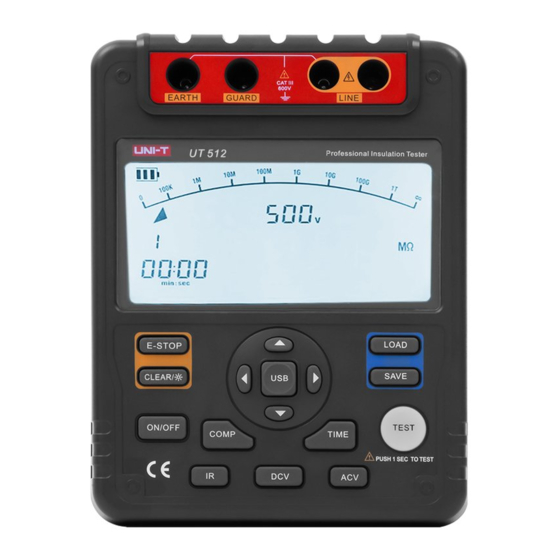
The Meter Structure
Below Figure 1 and Table 4 shows the Meter front
structure and description
Green
Black
Red
Figure 1. The Meter Front Structure
Table 4. Meter Front Description
1
LCD
2
Arrow Button
3
Emergency Stop
4
Data Clear the Display Backlight Button
5
Arrow Button
6
On/Off Button
7
Compare Button
8
Insulation Resistance Button
9
DC Voltage Measurement Button
10
Timer Button.
11
AC Voltage Measurement Button
12
Test Button
13
USB Button
14
Data Store Button.
15
Data Recall Button
16
Arrow Button
17
Arrow Button
18
LINE: High voltage input terminal
( Connected to two-plug red test lead )
19
High voltage line shielding input terminal
( Connected to two-plug red test lead )
20
GUARD: Grounding protection input terminal
( Connected to one-plug black test lead )
21
EARTH: High resistance measurement input
terminal ( Connected to one-plug green
test lead )
22
Testing leads:
Two-plug red test lead to one alligator clip.
One-plug black test lead to one alligator clip.
One-plug green test lead to one alligator clip.
Below Figure 2 and Table 5 shows the Meter side
structure and description
Figure 2. The Meter Side Structure
Table 5. Meter Side Description
1
Safety Shutter
2
Power adaptor Input Terminal
3
USB Port
Display
Table 6 and Figure 3 describe the display.
Figure 3. Display
Table 6. Display Description
Number
Meaning
Analogue bar graph
1
Risk of electric shock
2
3
Battery life indicator
4
Indicator for timer
5
Timer 1 symbol
6
Timer 2 symbo
7
Indicates selected pass/fail compare value
8
Indicator for power adaptor
9
The continuity buzzer is on
10
Indicator for data store full
11
Data store is on
12
Data recall is on
13
Indicator for polarization index
14
Step symbol
Compare result: Pass
15
16
Compare result: Fail
17
Indicator for DC voltage
18
Indicator for AC voltage
19
Indicates negative reading
20
Unit symbols
Indicator for clearing
21
Key Functions
Table 7. Key Description
Turn on or off the Meter. Press and
ON/OFF
hold the button for 1 second to turn the
Meter on. Press again to turn off the
Meter.
The Meter defaults at 500V range and
under continuous measurement of
insulation resistance when turned on.
E-STOP
Emergency stop button. Press this
button when the Meter crashes down
and cannot turn off the power.
CLEAR
Short press to turn on or off the display
/
backlight Long press to clear the stored data.
SAVE
Press to store the current measurement
value. The maximum number of stored
reading is 18. When the stored readings
memory is full, the Meter shows FULL
and stop storing. Press and hold
CLEAR /
to clear the stored value
in order to store the next measurement
value.
LOAD
Press once to recall the first stored
value.
Press again to exit Load feature.
Load feature can only be used when
there is no high voltage output.
When the insulation resistance
measurement has no testing voltage
output, press to select previous voltage
range.
Under load mode: press to recall the
previous stored value.
When the insulation resistance
measurement has no testing voltage
output, press to select next voltage
range.
Under load mode: press to recall the
next stored value.
When setting the timer for the
measurement of insulation resistance
or polarization index, press to
decrement the time. The maximum
length of time is 15 minutes and 30
seconds, the Meter will automatically
carry out measurement.
When compare function is enabled for
insulation resistance measurement,
press to decrement a resistance
comparing value.
After polarization index measurement,
press to display polarization index,
TIME 2 and TIME 1 insulation
resistance values in sequence.
When setting the timer for the
measurement of insulation resistance
or polarization index, press to
increment the time. The maximum
length of time is 30 minutes and 30
seconds, the Meter will automatically
carry out measurement.
When compare function is enabled for
insulation resistance measurement,
press to increment a resistance
comparing value.
After polarization index measurement,
press to display polarization index,
TIME 2 and TIME 1 insulation
resistance values in sequence.
Press once to start the data
USB
transferring to the computer via USB,
USB symbol shows on the display.
Press again to stop the data
transferring to the computer via USB,
USB symbol disappears.
Set a pass / fail limit for insulation tests.
COMP
The default value is 10M
TIME
Press to step through continuous,
timed and polarization index
measurements in sequence.
Press to turn on/off the output of
TEST
insulation resistance test voltage.
Press to initiate insulation resistance
IR
measurement
DCV
Press to initiate DC voltage
measurement
ACV
Pres to initiate AC voltage
measurement
Measurement Operation
This section explains how to make measurements.
Press and hold ON/OFF to turn on the Meter, press
again to turn off the Meter. The meter defaults at 500V
range and continuous measurement of insulation
resistance when turned on.
A. Measuring Voltage
Red
Green
Figure 4. Voltage Measurement
Operating Caution
To avoid harm to you or damage to the Meter,
please do not attempt to measure voltages
higher than 600V or 600V rms, although
readings may be obtained.
Special care should be taken when measuring
high voltage.
To measure voltage, set up the Meter as Figure 4 and
do the following:
1.
Press DCV or ACV button to select DC voltage or
AC voltage measurement
Advertisement

Subscribe to Our Youtube Channel
Related Manuals for UNI-T UT512


Summary of Contents for UNI-T UT512
- Page 1 Two-plug red test lead to one alligator clip. insulation resistance measurement, Make sure the Meter is turned off when Uni-Trend Model UT512 insulation resistance tester One-plug black test lead to one alligator clip. press to decrement a resistance opening the battery compartment.
- Page 2 Make sure the Meter is power off when you Insert the red test lead into two LINE terminals, the Relative humidity: 45~75%RH disconnect the UT512 power adaptor from the Meter. black one into GUARD and the green one into EARTH. It is highly recommended to use Uni-Trend supplied Connect the red and green alligator clip to the circuit A.
Need help?
Do you have a question about the UT512 and is the answer not in the manual?
Questions and answers