Table of Contents
Advertisement
Advertisement
Table of Contents

Subscribe to Our Youtube Channel
Related Manuals for DEVI DEVIreg 850


Summary of Contents for DEVI DEVIreg 850
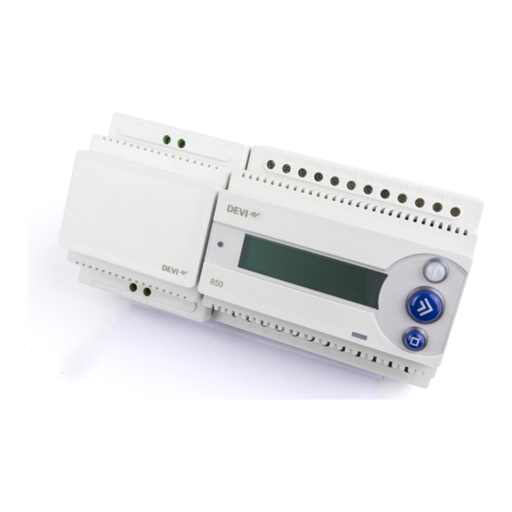
- Page 1 GB-DAS Installation and user manual DEVIreg™ 850 controller...
-
Page 2: Table Of Contents
Table of Contents 1: User Manual System overview ......... . 3 General use. -
Page 3: 1: User Manual
User Manual System overview The DEVIreg™ 850 system is capable of keeping outdoor areas free of ice and snow. The DEVIreg™ 850 can handle up to 2 independent areas, in any of the following combinations: Single roof system To keep gutters, valley gutters and down pipes free of ice and snow, and to prevent icicles from causing damage. - Page 4 User Manual When more than 1 area is controlled by the DEVIreg™ 850 system, it is also possible to prioritize the areas. Prioritizing makes it possible to operate 2 areas, even if the needed power for 2 areas is not present. The DEVIreg™...
-
Page 5: General Use
User Manual General use The DEVIreg™ 850 is operated via 3 buttons and an alpha numeric display capable of displaying information in various languages. Buttons The functions of the 3 buttons are: Info Shows additional information / help (Only active when lit) Next Next menu entry / next line / next letter Enter... -
Page 6: Menu System
User Manual Combined view (default): The combined view shows the status of both systems at A:Roof the same time. System A is shown on the upper display B:Ground line, and System B is shown on the lower display line. This view gives the user a quick overview of all the systems. Flipped view: The flipped view shows the status of 1 system at a time. -
Page 7: Possible Alarms During Operation
User Manual Possible alarms during operation Clogged drain Description: When clogged drain warning has been enabled, an alarm is raised when the system constantly has been detecting moisture for 14 days. If the DEVIreg™ 850 controls more than 1 system, and prioritiz- ing has been enabled, the time before clogged drain warning for the down-prioritized system, can be much longer. -
Page 8: Changing Parameters And Performance Of Systems
User Manual Changing parameters and performance of systems Several parameters for each system can be changed during and after the installation. For a complete understanding of how these parameters affect the performance of the roof and ground system, please refer to Appendix B: “How it works”. Only change the DEVIreg™... -
Page 9: Ground System
User Manual Ground system Melting temperature Changing the melting temperature will affect when the system is activated in case of moisture and low temperatures. The factory setting is 4°C. This means that the heating system will be activated if the temperature falls below 4°C and moisture is detected. -
Page 10: 2: Installer Manual
Installer Manual System overview The DEVIreg™ 850 can handle up to 2 independent areas, in any of the following combinations: (1 system, 1-4 roof sensors) (1 system, 1-4 roof sensors) (combi system) (2 systems, 2-4 sensors total, minimum 1 sensor per system) (dual system) (2 systems, 2-4 sensors total, minimum 1 sensor per system) (dual system) -
Page 11: Placement
Installer Manual Placement The DEVIreg™ 850 and power supply are designed for DIN rail mounting. When mount- ing please be aware of the following conditions: The DEVIreg™ 850 is designed and approved to operate in the temperature range -10°C to 40°C. The DEVIreg™... - Page 12 Installer Manual DEVIbus sensors RS232 White White Black White White Black DC output DC supply 13 14 15 16 17 18 19 20 21 22 23 24 DC-PSU 24V/24W DEVIreg™ 850 PSU 24V NA 1 2 3 4 5 6 7 8 9 10 11 12 220 / 240V~ 50 - 60 Hz ALARM...
- Page 13 Installer Manual B - 230V, 1-3 P/1-3 loads - System A C - 230V, 1-3 P/1-3 loads - System B 230 V cables 230 V cables...
- Page 14 Installer Manual System A System B 400 V cables 400 V cables F - Direct connection - System A G - Direct connection - System B 230 V cables 230 V cables...
-
Page 15: Installation Steps For System/Systems
Change setting with key: Accept setting with key: General Power on DEVIreg™ 850 Welcome to DEVIreg 850 III Select language Select language: E nglish System is being checked… Checki n g system Select system configuration... -
Page 16: Installation Of Roof System
Installer Manual Installation of roof system The installation of a DEVIreg™ 850 with 1 roof system has been selected. It is optional if the sensors are connected to the DEVIreg™ 850 before power on or dur- ing the installation. The system uses the output System A. If sensors for System A are not connected - do it now! Connect sensors System A... -
Page 17: Installation Of Ground System
Installer Manual Installation of ground system The installation of a DEVIreg™ 850 with 1 ground system has been selected. It is optional if the sensors are connected to the DEVIreg™ 850 before power on or dur- ing the installation. The system uses the output System A. If sensors for System A are not connected - do it now! Connect sensors System A... -
Page 18: Installation Of Combi System
Installer Manual Installation of combi system The installation of a DEVIreg™ 850 with 1 roof and 1 ground system has been selected. It is optional if the sensors are connected to the DEVIreg™ 850 before power on or dur- ing the installation. The first installed system (System A) is using the output System A. - Page 19 Installer Manual System B! Press when all sensors for System B are found… Installed System B is installed… System is being checked… Checki n g system Confi g system: System A Press to select system to configure. Confi g system: Press to configure selected system (naming sen- System B...
-
Page 20: Installation Of Dual System
Installer Manual Installation of dual system The installation of a DEVIreg™ 850 with 2 roof systems or 2 ground systems has been selected. It is mandatory that no sensors or only sensors for System A are connected to the the DEVIreg™ 850 before power up. Sensors for System B must be connected to the DEVIreg™... - Page 21 Installer Manual System B! Press when all sensors for System B are found… Installed System B is installed… System is being checked… Checki n g system Confi g system: System A Press to select system to configure. Confi g system: Press to configure selected system (naming sen- System B...
-
Page 22: Modification Of System(S)
Installer Manual Modification of system(s) It is possible to modify the installed systems on the DEVIreg™ 850. The following modi- fications are possible: When the DEVIreg™ 850 cannot communicate with a sensor, the DEVIreg™ 850 reports the error: “Errors detected!”. The DEVIreg™ 850 does not rely on malfunctioning sen- sors, and therefore the DEVIreg™... -
Page 23: Replacing A Malfunctioning Sensor
Installer Manual Replacing a malfunctioning sensor From the installer menu select Change system. The Checki n g system system is searching for connected sensors. The user selects the passive sensor, which should be Replace sensor: replaced with a new one. Sensor1 03FB2F Replace sensor: Sensor2 03FC24... -
Page 24: Add An Extra Sensor
Installer Manual Add an extra sensor From the installer menu select Change system. The Checki n g system system is searching for connected sensors. Add sensor: I D : 03ABC1 Press to loop through the found passive sen- sors or to cancel replace sensor. Cancel add Press when the correct new sensor to add is... -
Page 25: 3: Technical Specifications
Technical Specifications Technical data Voltage: 18-26 VDC 180-250 VAC, 50/60 Hz Power consumption: Max. 3 W Max. 8W (each) Max. 13W (each) Relay load capability: 230V ~ 2A 230V ~ 15A 230V ~ 15A 1A (power factor 0.3) IP class: IP 20 IP 67 IP 67... -
Page 26: Factory Settings
Technical Specifications Factory settings Roof System Function Factory settings Range/Options Moisture level 5 to 95 (5 being the most sensitive to moisture) Melting temperature 1.5°C 0.0°C to 9.9°C Post-heat 1 hour 0 to 9 hours Clogged drain On/off System mode Automatic Ground system Function... -
Page 27: A: Menu System
Appendix A A: Menu system Main menu System System Only visible when System B is installed ! System menu System menu (A / B) Installer menu... - Page 28 Appendix A View sensor measurements View sensor measurements View system parameters (Roof systems) (Roof system) View sensor parameters View sensor measurements View system parameters (Ground system) (Ground system)
- Page 29 Appendix A Installer menu Installer menu Change system View statistics...
- Page 30 Appendix A Change system Change system Only if any passive (disabled) sensors are working again! If no new sensor(s) found If new sensor(s) found, but no If new sensor(s) found and (Example showing ground passive sensor(s) found. passive sensor(s) found. system).
- Page 31 Appendix A View statistic View statistics...
-
Page 32: B: How It Works
Appendix B B: How it works Roof system The roof system is fully automated. Standby (No heating) It gathers information on moisture Temperature > and temperature via digital sen- Temperature < Melting temperature Melting temperature Moisture > Moisture limit sors continuously. The sensors are Measuring After 3 hours Melting... -
Page 33: Ground System
Appendix B Ground system Temperature < The ground system is Standby temperature Standby Standby Temperature >- fully automated. It gathers Standby temperature (No heating) Mantaining standby temperature information on moisture Temperature < Melting temperature (Heating) Moisture > Moisture limit and temperature via digital Melting sensors continuously. - Page 34 Appendix B Post-heating If the reason for ending a heating period is a decrease of moisture to below the chosen level, the post-heating period will start. Post-heating ensures that no ice and snow is left on the roof. If system priority is low, heating might be paused at any time! The ground system uses heated sensors which under normal circumstances will hold a temperature of 1.5°C.
-
Page 35: Security And Energy Consumption
Appendix B Security and energy consumption High security – higher energy consumption If a high degree of security against ice and snow is wanted, make the following adjust- ments of the operation parameters: This will give a high degree of security in even dry areas. Low security –... -
Page 36: C: Psu And Feeder Cable
Appendix C C: PSU and feeder cable Ground system 1 pcs. PSU 2 pcs. PSU 24VDC, 24 VDC 24 W 24 W in parallel Number 1 or 2 * of sensors: Cable type Max. length (m) Max. length (m) Max length (m) 1 mm²... - Page 38 Guarantee case of faulty DEVIreg thermostats, system which we are sure will serve to DEVI reserves the right to repair the unit improve the comfort and economy of free of charge and without any unrea- your home. sonable delays for the customer.
- Page 39 The DEVI Guarantee Guarantee Certificate The DEVI™ Guarantee is granted to: Name: Address: Postal code: Phone: Please observe! In order to obtain the DEVI Guarantee, the following must be carefully filled in. See other conditions on previous page. Electrical Installation by:...
- Page 40 Article: 08095387 ˚C...
Need help?
Do you have a question about the DEVIreg 850 and is the answer not in the manual?
Questions and answers