Table of Contents
Advertisement
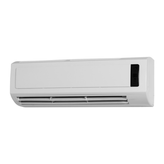
MODEL HW-ECM
INSTALLATION,
OPERATION &
MAINTENANCE
MANUAL
Low Temperature
High Wall Heating/Cooling Fan Coil
Units up to 2 Ton Capacity
A. General Description ...........................................................2
B. Technical Data .................................................................3-5
General Specification ...........................................................3
Coil Data ..............................................................................4
Sound Power and Pressure Data ........................................4
Dimensional Drawings .........................................................5
C. Service and Installation ................................................6-11
Installation of High-Wall Unit ................................................6
Selecting a Location ............................................................6
Mounting Plate Dimensions .................................................7
Installing the Mounting Plate ................................................7
Drilling the Condensate Drainage Hole ...............................8
Installing the Hydronic Unit ..................................................8
Drainage Piping Works ........................................................8
Unit Maintenance and Preparation ......................................9
Opening and Closing of Lift-Up Grille Cover ........................9
Removing Front Cover Assembly ........................................9
Air Purging ...........................................................................9
Wiring Connections ..............................................................9
IN UNITED STATES: 260 NORTH ELM ST. WESTFIELD, MA 01085 800-465-8558 / FAX (413) 564-5815
IN CANADA: 7555 TRANMERE DRIVE, MISSISSAUGA, ONTARIO, L5S 1L4 (905) 670-5888 / FAX (905) 670-5782
S Type Control ............................................................10-14
Definition of Input/Output ...................................................10
Wiring Diagram Full Control PCB - S Control Type .......... 11
Configuration Settings .......................................................12
Control Logics for 2-Pipe System ......................................13
With Thermoelectric Valve Configuration ...........................13
Sleep Mode ........................................................................14
Auto Fan Speed .................................................................14
LED Lights .........................................................................14
LED Display and Error Description ....................................14
W Type Control ...........................................................15-16
Definition of Input/Output ...................................................15
W Control Type ..................................................................16
F. Users Interface .................................................................17
Remote Control Handset ...................................................17
G. Sensor Resistance R-T Conversion Table ................18-19
H. Troubleshooting Guide ...................................................20
HWL2-0818
Advertisement
Table of Contents

Related Manuals for Mestek HW-06-ECM


Summary of Contents for Mestek HW-06-ECM
-
Page 1: Table Of Contents
HWL2-0818 MODEL HW-ECM INSTALLATION, OPERATION & MAINTENANCE MANUAL Low Temperature High Wall Heating/Cooling Fan Coil Units up to 2 Ton Capacity A. General Description ............2 D. Control Specifications: Complete Control PCB - B. Technical Data ..............3-5 S Type Control ............10-14 General Specification ............3 Definition of Input/Output ...........10 Coil Data ................4 Wiring Diagram Full Control PCB – S Control Type .. -
Page 2: General Description
INVESTING IN QUALITY, RELIABILITY & PERFORMANCE. ISO 9001 QUALITY World Leading Design and Technology Every product is manufactured to meet the Equipped with the latest air-conditioning test stringent requirements of the internationally rooms and manufacturing technology, we recognized ISO 9001 standard for quality produce over 50,000 fan coil units each year, assurance in design, development and all conforming to the highest international... -
Page 3: Technical Data
Air Grille Distribution - all units are equipped with both deflector blades and independent directional vanes, enabling supply air to be automatically distributed, and air flow and direction to be customized. Microprocessor controls (S3 type) The PCB (printed circuit board) Modbus microprocessor controls functionality of the indoor-fan motor, water valves (ON/OFF or modulating) and electric heater (optional), to maintain room conditions at a user-defined set point. Temperature settings, fan speeds and other control functions can be changed by either infrared handset or wired wall pad. Electro-mechanical controls (W3 type) A 24VAC power strip is provided. Louver stepping motor controlled from PCB. Normally open or normally closed contacts are standard, allowing connection and control of field devices. -
Page 4: Coil Data
Coil Data – 2-Pipe Systems Fin Height Fin Length Tube Diameter Model Fins per Inch No. of Rows No. of Copper No. of Circuits (inch) (inch) (inch) HW-06-ECM 14.1 26.8 HW-15-ECM 14.1 26.8 19.5 HW-18-ECM 14.1 26.8 Sound Power and Pressure Data Sound Pressure Model HW-06-ECM HW-15-ECM HW-18-ECM A-weighted 33.8... -
Page 5: Dimensional Drawings
Dimensional Drawings – HW-06/15/18-ECM HW-06/15/18-ECM Unit Dimensions 1.57 4.13 34.45 2.17 4.13 R0.78 2.36 2.91 Unit Dimensions 7.87 2.17 1.18 1.18 8.66 9.02 0.39 11.81 Unit Dimensions 26.18 6.69 27.95 4.92 (All dimensions are shown in inches) -
Page 6: Service And Installation
C. Service and Installation Operating Limits Power Supplies Volt Phase 110-120 Water Circuit Minimum entering water temperature 35.6°F (+2°C ) Maximum entering water temperature 176°F (+80°C) Water side recommended maximum pressure 232 PSI (1600 kPa) Installation of HighWall Unit Selecting a Location Select the location for the HighWall unit with the following considerations: 1. The air inlet and outlet area should be clear without obstructions. The air should flow freely. 2. The HighWall unit should be mounted on solid wall. 3. The location should allow easy access to connect water pipes easily achieve drainage. 4. Ensure the clearance around the fan coil unit conforms to the following drawing. 5. The unit should be installed higher than eye level. 6. Avoid installing the unit with direct sunlight. Higher than eye level Notes: Required clearance for maintenance and servicing is as shown above. All dimensions shown in inches. -
Page 7: Mounting Plate Dimensions
Mounting Plate Dimensions (All dimensions are in inches) Installing the Mounting Plate 1. Select the structural position (e.g. a pillar or lintel) on the wall. 2. Then temporarily fasten the mounting plate on the wall with a steel nail. 3. Mount the mounting plate horizontally as shown in the above figure or by means of gradiometer. Failure to follow this may cause water to drip indoors and create atypical noise. 4. Fix the mounting plate by means of expansion screws or tapping screws. -
Page 8: Drilling The Condensate Drainage Hole
Drilling the Condensate Drain Hole 1. Ensure that the hole for condensate drain is correctly positioned. The height should be lower than the bottom edge of the indoor unit. 2. Drill a 2.5" diameter hole with a descending slope. 3. Seal it off with putty after installation. Installing the Hydronic Unit 1. Pass the piping through the hole in the wall and hook the indoor unit on the mounting plate by the upper hooks. 2. Move the body of the unit from side to side to verify if it is securely fixed. 3. While pushing the unit toward the wall, lift it slightly from beneath to hook it up on the mounting plate by the lower hooks. 4. Make sure the unit firmly rests on the hooks of the mounting plate. Drain Piping Works 1. Install the drain hose so that it slopes downward slightly for free drainage. Avoid installing it as shown in the below illustrations marked with an “X”. 2. Put water in the drain pan and make sure that the water drains outdoors. 3. If the flexible drain hose provided with the indoor unit is not long enough, please extend it by joining it to a field supplied extension. Be sure to insulate the connecting part of the extension with a shield pipe as shown. 4. If the attached drain hose passes through an indoor area, insulate it with insulation material. -
Page 9: Unit Maintenance And Preparation
Unit Maintenance and Preparation Opening and Closing Of Lift-Up Grille Cover Open the grille cover by lifting from the bottom position indicated Close the grille cover by pressing down at the positions indicated by the arrows. by the arrows.. Removing Front Cover Assembly 1. Set the horizontal louver to the horizontal position. 2. Remove the screw caps below the louver, and then remove the mounting screws. 3. Open the lift-up grille cover by grasping the panel at both sides as shown above. 4. Remove the remaining screws located in the center of the front cover. 5. Grasp the lower part of the front cover and pull the entire assembly out and up towards you. Air Purging 1. After connecting the water inlet and outlet pipes to the main supply lines turn on the main breaker and operate the unit in COOLING mode. -
Page 10: Control Specifications: Complete Control Pcb - S Type Control
D. Control Specifications: Complete Control PCB - S Type Control Abbreviations Ts = Setting temperature AUX1 = Hot water free contact Tr = Room air temperature AUX2 = Chilled water free contact Ti1 = Chilled water coil temperature MTV1 = Chilled Motorized valve Ti2 = Hot water coil temperature MTV2 = Hot Motorized valve Definition of Input/Output Code 2-Pipe Return air sensor Return air temperature (Tr) Analogue Input Coil sensor Chilled / hot water coil circuit (Ti1) Input LED display / IR reciever X-DIS1 Digital communication port to LED display / IR receiver board. Window contacts: for remote ON/OFF (when DIPB SW1 = 1). Economy Digital input Occupancy contact On/Off contacts: for remote activation of economy mode (when DIPB SW1 = 0). Phase Power input Neutral Power supply: 115V/1Ph/60Hz Earth Fan driver 2-pipe coil circuit valve output - chilled / hot water valve. Voltage output Valve 1 MTV1 Voltage output (L) Valve 2 MTV2 Reserved Stepping motor CN1 / CN2 Louver stepping motor relay... -
Page 11: Wiring Diagram Full Control Pcb - S Control Type
Wiring Diagram Full Control PCB - S Control Type... -
Page 12: Configuration Settings
Motorized Fan Speed Settings for Different Models on DIPB: Speed (RPM) Unit Model Medium High HW-06-ECM HW-15-ECM 1100 HW-18-ECM 1100 1300 Default RPM 1200 1350 Mode configuration: DIPA-S1 Model Model setting Cool-Heat Cool-Heat + booster heater Cooling only Cool + primary heater HighWall Unit ON/OFF There are 3 ways to turn the system on or off: a) By the ON/OFF button on the handset or wired wall pad. b) By the programmable timer on the handset or wired wall pad. c) By the manual control button on the HighWall unit. Power On Setting There are 3 ways to turn the system on or off: a) Handset only user interface: When the power ON signal is received by the unit, the Mode, Fan Speed, Set temperature and Louver setting will be the same as the handset setting before the last power OFF. b) When the power ON signal is received by the HighWall unit, the Mode, Fan Speed, Set temperature, Louver setting and... -
Page 13: Control Logics For 2-Pipe System
Control Logics For 2-Pipe System (Standard Unit) With Thermoelectric Valve Configuration COOL MODE a) MTV2, AUX1 and heater are always off. b) If Tr ≥ Ts + 1.8ºF (or + 7.2ºF if economy contact is activated), then cool operation is activated and MTV1 and AUX2 are turned on. Indoor fan runs at set speed. c) If Tr < Ts, then cool operation is terminated and MTV1 and AUX2 are turned off. Indoor fan runs at set speed. d) The range of Ts is 60.8 - 86ºF e) Indoor fan speed can be adjusted to low, medium, high and auto. f) When turned on, MTV1 requires 30 seconds before it is fully open. g) When turned off, MTV1 requires 120 seconds before it is fully closed. h) When the unit is turned off, the indoor fan will shut down after 5 seconds. LOW TEMPERATURE PROTECTION OF INDOOR COIL a) If Ti1 ≤ 35.6ºF for 2 minutes, then MTV1 and AUX2 are turned off. If indoor fan is set for low speed, it will run at medium speed. If it is set at medium or high speed, it will keep running at the same speed. b) If Ti1 ≥ 41ºF for 2 minutes, then MTV1 and AUX2 are turned on. Indoor fan runs at set speed. FAN MODE a) Indoor fan runs at the set speed while heater, MTV1, MTV2, AUX1 and AUX2 are turned off. b) Indoor fan speed can be adjusted to low, medium and high. PRE-HEAT a) If Ti1 < 96.8ºF (or 82.4ºF depending on DIP setting), then MTV1 and AUX1 are turned on, indoor fan runs at 200RPM. b) If Ti1 ≥ 100.4ºF (or 86ºF depending on DIP setting), then MTV1 and AUX1 are turned on, indoor fan runs at set speed. -
Page 14: Sleep Mode
Sleep Mode a) The sleep mode can only be set when the unit is in cool mode or heat mode. b) If the sleep mode is activated when the unit is in cool mode, then the indoor fan will run at low speed and Ts will increase by 3.6ºF over 2 hours. c) If the sleep mode is activated when the unit is in heat mode, then the indoor fan will run at set speed and Ts will decrease by 3.6ºF over 2 hours. d) Changing the mode of operation will cancel the sleep mode. The cool mode sleep profile is: The heat mode sleep profile is: Auto Fan Speed In COOL mode, the fan speed cannot change until it has run In HEAT mode, the fan speed cannot change until it has run for more than 30 seconds. for more than 30 seconds. Fan speed is regulated according to the profile below. LED Lights For all units Power / Operation LED light (both green) Unit on Power LED Off, Operation LED On Unit in standby Power LED On, Operation LED Off LED Display and Error Description For all units - Operation LED light (Green) Error Description Blink Reason Remedy Only for unit with EH. -
Page 15: Control Specifications: Flexible Control Pcbw Type Control
E. Control Specifications: Flexible Control PCB - W Type Control Abbreviation Ti1 = Chilled water coil temperature Definition of Input/Output Code 2-Pipe Analogue Input Chilled water Sensor Coil sensor (Ti1) High Speed 24 Voltage input (NO). If any speed is powered, the unit is turned on. Power input Medium Speed If no speed receives power, the unit is turned off. Low Speed Phase Power input Neutral Power supply: 115V/1Ph/60Hz Earth EC motor EC motor output Stepping motor CN1, CN2 Stepping motor output Output Electric Heater Signal CN4, CN5 Electric Heater control signal LED Display X-DIS LED Display signal... -
Page 16: Wiring Diagram Flexible Control Pcb - W Control Type
Wiring Diagram Flexible Control PCB - W Control Type... -
Page 17: Users Interface
F. Users Interface Remote Control Handset Swing It is not available . Attention When unit with handset is the master unit, its settings are automatically sent to the slave units; Auto Cool - Heat operation will be applicable in 4- pipe system only. “Swing”... -
Page 18: Sensor Resistance R-T Conversion Table
G. Sensor Resistance R-T Conversion Table Resistance : R (77°F) = 10KΩ ± 1% Beta Constant : B (25/85) = 3977 ± 1% Rmin Rnom Rmax Rmin Rnom Rmax (°F) (KΩ) (KΩ) (KΩ) (°F) (KΩ) (KΩ) (KΩ) 182.7 191.8 39.2 26.11 26.9 27.71 -20.2 163.4 171.5 179.9 24.85 25.59 26.34 -18.4 153.6 161.1 168.9 42.8 23.65 24.35 25.05 -16.6 144.4 151.3... - Page 19 Resistance : R (77°F) = 10KΩ ± 1% Beta Constant : B (25/85) = 3977 ± 1% Rmin Rnom Rmax Rmin Rnom Rmax (°F) (KΩ) (KΩ) (KΩ) (°F) (KΩ) (KΩ) (KΩ) 100.4 5.614 5.759 5.907 1.417 1.474 1.532 102.2 5.387 5.53 5.673 168.8 1.37 1.426 1.482 5.172 5.31 5.451 170.6 1.326 1.379 1.434 105.8 4.966 5.101...
-
Page 20: Troubleshooting Guide
H. Troubleshooting Guide IN UNITED STATES: 260 NORTH ELM ST. WESTFIELD, MA 01085 800-465-8558 / FAX (413) 564-5815 IN CANADA: 7555 TRANMERE DRIVE, MISSISSAUGA, ONTARIO, L5S 1L4 (905) 670-5888 / FAX (905) 670-5782...
Need help?
Do you have a question about the HW-06-ECM and is the answer not in the manual?
Questions and answers