Table of Contents
Advertisement
Quick Links
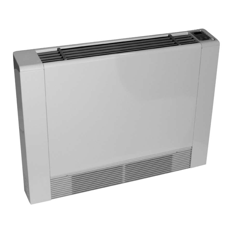
MODEL UT
INSTALLATION,
OPERATION &
MAINTENANCE
MANUAL
Low Temperature
ThinWall Heating/Cooling Fan Coil
Units up to 1 Ton Capacity
3.1 Specification Table.................................................................
3.2 Working Conditions ...............................................................
3.3 Overall Dimensions ...............................................................
4.1 Installation Precautions .........................................................
4.2 Installation: Positioning the Unit ............................................
4.3 Minimum Clearances .............................................................
4.3a Floor Installation ..................................................................
4.4 Water Connections ................................................................ 7-8
4.5 Condensate Discharge ..........................................................
4.6 Venting Air .............................................................................
IN UNITED STATES: 260 NORTH ELM ST. WESTFIELD, MA 01085 800-465-8558 / FAX (413) 564-5815
IN CANADA: 7555 TRANMERE DRIVE, MISSISSAUGA, ONTARIO, L5S 1L4 (905) 670-5888 / FAX (905) 670-5782
..................................................
..................................
2
5.1 Control Function ....................................................................
5.2 Setting Temperature .............................................................. 11-12
2
5.3 Usage of Remote Control ...................................................... 13-14
5.4 Adjustable Parameters ..........................................................
3
3
6.1 Maintenance .......................................................................... 15-16
4
6.2 Trouble Shooting ...................................................................
5
7.1 Networking Wiring Diagram ...................................................
5
7.2 Connections ..........................................................................
5
7.3 Wiring Diagram ......................................................................
6
Warranty ......................................................................................
9
Terms and Conditions of Sale .....................................................
9
UT2-1116
10
14
16
17
17
18
19
19
Advertisement
Table of Contents
Troubleshooting

Related Manuals for Mestek UT-87


Summary of Contents for Mestek UT-87
-
Page 1: Table Of Contents
UT2-1116 MODEL UT INSTALLATION, OPERATION & MAINTENANCE MANUAL Low Temperature ThinWall Heating/Cooling Fan Coil Units up to 1 Ton Capacity SECTION 1: INTRODUCTION SECTION 5: START-UP AND OPERATION ..........5.1 Control Function ..............5.2 Setting Temperature .............. 11-12 SECTION 2: SAFETY PRECAUTIONS ........ -
Page 2: Section 1: Introduction
Section 1: Introduction Thank you for choosing the ThinWall water fan coil. The products In case of water leaks, turn the master switch of the system to strictly comply with design and production standards to provide “OFF” and close the water taps. As soon as possible call the high quality operation, perfect performance, high reliability and manufacturer’s technical service department or professionally good adaptability. -
Page 3: Section 3: Specifications
Section 3: Specifications 3.1 Specification Table Model UT-87 UT-135 UT-196 UT-246 UT-320 Heating Capacity* BTU/H 8700 13500 19600 24600 32000 Water Flow Rate Pressure Drop Cooling Capacity** TONS 1 1/4 Water Flow Rate Pressure Drop Air Volume Noise DB (A) -
Page 4: Overall Dimensions
Section 3: Specifications (continued) 3.3 Overall Dimensions (Inches) Figure 2 Product Model UT-87/135/196/246/320 5-1/8 -1/8 1-5/8 3-3/8 3-5/16 Figure 3 Product Model UT-87/135/196/246/320 -1/8 -5/8 -3/8 -5/16 Unit Model UT-87 UT-135 UT-196 UT-246 UT-320 27-1/2 35 -1/2 43-3/8 51-1/8 59-1/16... -
Page 5: Section 4: Installation
Section 4: Installation 4.1 Installation Precautions Removal of Side Panel (Fig. 6) Dismount the upper grill (Fig. 6 Ref. A) by unscrewing the To ensure that the installation is performed correctly fixing screws. carefully follow the instructions indicated in this manual. Failure to follow instructions indicated not only can cause Lift the cover (Fig. -
Page 6: Floor Installation
Section 4: Installation (continued) 4.3a Floor Installation If installing the unit on the floor, the footing should be mounted (Feet shipped loose as optional equipment): First, lay down the unit and match up the screw holes (Ref. Fig. 10 Item A/B/C/D), finally apply four screws to each side to affix the feet. (See Fig. 9 and Fig. 10). Figure 9 Figure 10... -
Page 7: Water Connections
Section 4: Installation (continued) Do not over-tighten the screws so that the brackets can be adjusted with a spirit level (Fig. 11). The fully tighten the four screws to block the two brackets. Mount the unit, checking that it fits correctly onto the brackets and checking that it is stable (Fig. 12). fig.8 Figure 11 Figure 12... - Page 8 Section 4: Installation (continued) Connection methods for flexible water connectors Figure 15 Connecting method I with valve (optional) Figure 16 Connecting method II with valve (optional) Flexible water connector Flexible water connector water outlet water outlet Flexible water connector water inlet Flexible water connector water inlet Figure 17...
-
Page 9: Condensate Discharge
Section 4: Installation (continued) 4.5 Condensate Discharge Figure 19 When mounting the condensation discharge device, connect to the condensate collection tray discharge union (Fig. 19 Ref. C) a pipe for the outflow of the liquid (Fig. 19 Ref. B) blocking it inadequately. The condensate discharge network must be suitably sized (minimum inside pipe diameter 5/8"). -
Page 10: Section 5: Start-Up And Operation
Section 5: Start-Up and Operation 5.1 Control Functionality (Orange)low fan speed indicator light (Yellow)medium fan Cooling indicator speed indicator light light green HIGH COOL HEAT (Blue)high fan Heating indicator speed indicator light light red About buttons: ON/OFF BUTTON. Pressing this button will start up or shut down the unit. Press this button and select the mode you want set: Cooling mode: cooling indicator light stays on (green) Heating mode: heating indicator light stays on (red) -
Page 11: Setting Temperature
Section 5: Start-Up and Operation (continued) 5.2 Temperature Setting Indoor ambient temperature When on the main interface of heating, cooling and automatic mode, you can press once to check the set temperature. Press again to increase or decrease the set temperature. Press or ON/OFF button to change mode, fan speed or shut down the unit HIGH... - Page 12 Section 5: Start-Up and Operation (continued) Set temperature in heating mode System will save user's setting and return back to main interface if there Press to save settings COOL HEAT HIGH and change modes of the unit. is no operation on buttons in 5s. Press Press switch button to save settings and...
-
Page 13: Usage Of Remote Control
Section 5: Start-Up and Operation (continued) 5.3 Using the Remote Control Ventilation Mode Dehumidification Mode Cooling Mode Heating Mode Auto Mode Sleeping Function Signal Emission AU TO Wind Speed Temperature Wind Direction Time Off TIME ON TIME OFF Time V alue POWER ON/OFF Mode Switch Wind Speed Regulation... -
Page 14: Setting Temperature
Section 5: Start-Up and Operation (continued) Functioning of “F.Cool” and “F.Heat” (3) When the sleep function is activated, the icon will be shown at the top right corner of the LCD screen on By pressing the key “F.Cool”, the system will automatically the remote. -
Page 15: Section 6: Maintenance And Trouble Shooting
Section 6: Maintenance and Trouble Shooting 6.1 Maintenance Cut off power supply before cleaning or maintaining the unit. To guarantee reliable service and comfort, it is suggested to maintain and clean the unit every 6 months. Take the following steps to clean up the filter regularly: (1) Lift the grill (A) upward (Fig. -
Page 16: Trouble Shooting
Section 6: Maintenance and Trouble Shooting (continued) (3) Set the filter net and the air return grill to the original place. (Fig. 27). (4) Clean up the outer unit with a soft, damp rag (Fig. 28). To protect the paint-coat of the unit, do not use a rough sponge or corrosive detergent. -
Page 17: Section 7: Wiring
Section 7: Wiring 7.1 Networking Wiring Diagram MD1001 K Y IN blue +12V G N D ye llow MD1001 +12V MD1001 E lec trica l Control Module o f Vertical Water Fa n Coil +12V N E T c ommunica tion or on-line Port MD1001... -
Page 18: Wiring Diagram
Section 7: Wiring (continued) 7.3 Wire Connection A m bie n t Te m pe r a tu r e C o il Te m pe r a tu r e E V : E le c tr o m a g n e tic Valve F M F a n Motor S ensit ive Swit ch T r a n s fo r m e r... -
Page 19: Warranty
Send or fax all orders ($50.00 minimum billing) to: good order to transportation companies. All orders are accepted subject to delays on account of government requirements, strikes, accidents, or Mestek other causes beyond our control. 260 North Elm Street Westfield, MA 01085 Minimum Orders Tel. - Page 20 IN UNITED STATES: 260 NORTH ELM ST. WESTFIELD, MA 01085 800-465-8558 / FAX (413) 564-5815 IN CANADA: 7555 TRANMERE DRIVE, MISSISSAUGA, ONTARIO, L5S 1L4 (905) 670-5888 / FAX (905) 670-5782...
Need help?
Do you have a question about the UT-87 and is the answer not in the manual?
Questions and answers