Table of Contents
Advertisement
Advertisement
Table of Contents

Related Manuals for Harsen GU641B


Summary of Contents for Harsen GU641B
- Page 1 ® Harsen Manual GU641B Genset Controller HM1016ER1...
- Page 2 CAUTION: A CAUTION indicates a potentially hazardous situation which, if not avoided, could result in damage to equipment or property. NOTE: A NOTE provides other helpful information that does not fall under the warning or caution categories. Harsen ®...
- Page 3 Controllers contain static-sensitive parts. Observe the following precautions to prevent damage to these parts: Do not disassemble the rear back of controller and touch the components or conductors on a printed circuit board. Harsen ®...
- Page 4 Manual History HM1016ER1 History Rev. Date Editor Validation Changes HM1016ER1 2011.1.1 Harsen ®...
-
Page 5: Table Of Contents
2. Outline Dimension Drawings and Controller Wiring………………………………………………… 3. Panel Operation……………………………………………………………………………………………… 4. Control and Operation Instruction………………………………………………………………………… 5. Measure and Display Data………………………………………………………………………………… 6. Pre-alarm and Shutdown Alarm…………………………………………………………………………… 7. Parameters Setting…………………………………………………………………………………………… 8. Installation Guide…………………………………………………………………………………………… 9. LCD displays and Menu System…………………………………………………………………………… 10. Technical Specification……………………………………………………………………………………… Harsen ®... -
Page 6: Description
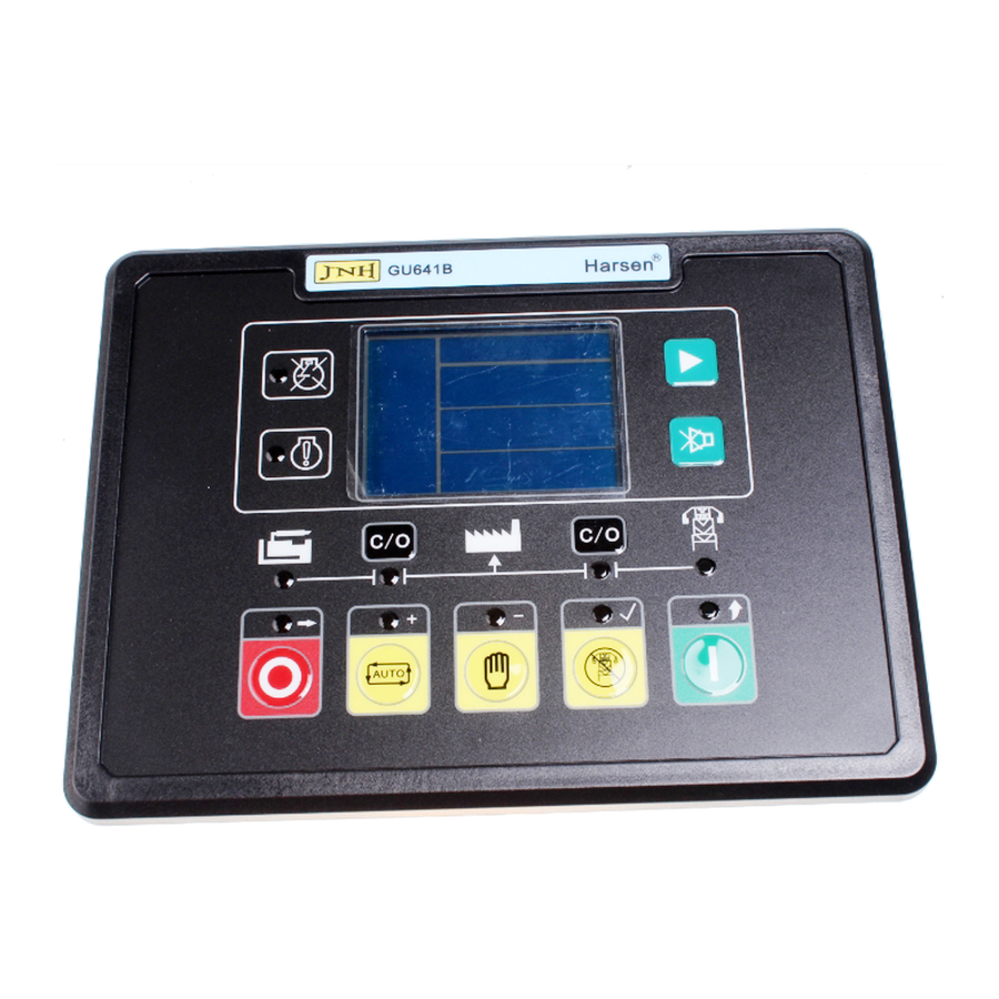
HM1016ER1 1. Description GU641B is a new generation Automatic Mains (Utility) Failure module for single Genset, which adopts bran-new outline configuration, focus on the requirements of customers, and perfectly improves the performance of controller. It fully meets the auto control requirements of different kinds of Genset for user or special assembly factory. -
Page 7: Outline Dimension Drawings And Controller Wiring
Manual Outline Dimension Drawings and Controller Wiring HM1016ER1 2. Outline Dimension Drawings and Controller Wiring 2.1 Following Details: Module Dimensions W192mm×H144mm Panel Cutout W174mm×H126mm Thickness D56mm (without connection) Harsen ® Page 2/54... - Page 8 12V/24V (8-35Vdc continuous) Battery supply {-B} 2.5mm² Ground 2.5mm² NOTE: Relay output 3 and 4 are respectively configured as GCB and MCB close/open relay when default setting, however both can be reconfigured by user if required. Harsen ® Page 3/54...
- Page 9 Manual Outline Dimension Drawings and Controller Wiring HM1016ER1 2.3 Typical Wiring Diagram A fuse with the rating of 1A shall be provided external to the equipment. Harsen ® Page 4/54...
-
Page 10: Panel Operation
TEST mode, the LED above the push button is illuminated, the controller starts the generator simulating Mains failure and the activation of “remote start signal”. When in parameters setting mode, this button is used to enter into submenu / confirm modification. Harsen ® Page 5/54... - Page 11 LED will illuminate when GCB/MCB is closed and power supplied by Gen / Mains, LED will flash when GCB / MCB failure occurs. MAINS Normal LED Mains normal LED will illuminate after both voltage and frequency of the Mains reach the preset value range. Harsen ® Page 6/54...
-
Page 12: Control And Operation Instruction
If MCB close/open relay is closed, the timer for MCB closing is activated, when it times out, if the controller does not receive the feed back signal from the Mains Aux. Switch’s contact, then Mains fail to load is activated. Harsen ® Page 7/54... - Page 13 During cranking or idle period, if the remote start signal is inactive or Mains voltage resumes to normal, the controller stops the start procedure, then recovers to the original standby status. Under any conditions, GEN. ON delay only can be started after Safety-on Delay times out. Harsen ® Page 8/54...
- Page 14 Start Failure: When the procedure above repeats again and again and reaches the preset number of crank attempt, the crank relay output is then de-engised. The failure LED illuminates and the LCD displays Fail to Start. Harsen ® Page 9/54...
- Page 15 If Genset has started since Mains fail to load, when failure is removed and controller unlocked by pressing reset button, GCB close/open relay opens, MCB close/open relay closes, transfer switch switches the load to Mains. Harsen ® Page 10/54...
- Page 16 If you press the “C/O” button of Gen when Mains is on load, the MCB close/open relay will be opened first, then Mains is off load, the GCB close/open relay closes later, Gen is on load. Harsen ® Page 11/54...
- Page 17 After a delay (same as Stop delay) fuel relay de- energises, disconnecting the supply from the fuel solenoid. Other control sequences are same as engine whose fuel solenoid is N. C. type. Harsen ® Page 12/54...
- Page 18 For preheat mode 4, preheat function is active immediately when the controller is switched on power. During crank period, the Preheat relay output will not energise in any of above modes. LCD displays icon of preheat operating status when preheat relay output energises: Harsen ® Page 13/54...
- Page 19 If the speed falls below 150RPM within safety-on time, controller will be reset and return to standby status. CAUTION: We normally don’t recommend using the second method to solve this condition. Pay attention to the installation of PB switch to avoid cranking when the Genset is running. Harsen ® Page 14/54...
- Page 20 T5- idle time T3- pre-heat time T6- Stop delay NOTE: If T4 is longer than T5, oil pressure protection is ignored during T5. If T4 is shorter than T5, oil pressure protection becomes effective after T4 in T5. Harsen ® Page 15/54...
-
Page 21: Measure And Display Data
Engine speed RPM (signal derived from magnetic pick-up or generator Hz) Engine oil pressure Bar (signal from engine LOP sensor) Engine coolant temperature ℃ ℃ ℃ ℃ (signal from engine HET sensor) Battery voltage Vdc Genset Running Hour Hour Harsen ® Page 16/54... -
Page 22: Pre-Alarm And Shutdown Alarm
OVER CURRENT: configure “Overcurrent action” as “warning”, if controller detects that any phase output current exceeds the “Overcurrent level” after the safety-on timer has expired, the pre-alarm LED illuminates and the buzzer sounds, LCD flashing high value icon. Harsen ® Page 17/54... - Page 23 To make the pre-alarm for GCB/MCB FAILURE active, please configure one of the configurable inputs as Gen/Mains Aux. Switch Closed and connects the switch’s N.O. Aux. contact to this port. After pre-alarm occurred, the controller is locked out, you must press reset button to remove. Harsen ® Page 18/54...
- Page 24 Alarm”, Genset stops, the Shutdown alarm LED illuminates and buzzer sounds, LCD displays: For example, “rating voltage” preset as: 220V, “GEN-V over Alarm” preset as: 115%, when any phase output voltage of generator exceeds this value, LCD displays high value icon for corresponding phase. Harsen ® Page 19/54...
- Page 25 OVER CURRENT BATT. UNDER VOLT GEN. OVER VOLT BATT. OVER VOLT GEN. UNDER VOLT START FAILURE OVERLOAD STOP FAILURE P-SENSOR OPEN EMERGENCY STOP D-INPUT * LOW OIL PRESS GCB FAILURE ENGINE HIGH TEMP. MCB FAILURE OVER SPEED Harsen ® Page 20/54...
-
Page 26: Parameters Setting
Used to define the rated voltage (phase to neutral) of Gen and Mains, rated VPh-Ph = “Rated ph- voltage” * 1.732. Reference value for judging over/under voltage. Rated current: Used to define the rated current of generator. Reference value for judging current. Harsen ® Page 21/54... - Page 27 Parameters Setting HM1016ER1 Voltage type: There are 5 kinds of voltage input type: “Y” 3P4W, “△” 3P4W, 3P3W, 1P3W, 1P2W. 1— “Y” 3P4W (3 phases 4 wires star): 2— “△” 3P4W (3 phases 4 wires angle): Harsen ® Page 22/54...
- Page 28 Manual Parameters Setting HM1016ER1 3— 3P3W (3 phases 3 wires): 4— 1P3W (single phase 3 wires): 5— 1P2W (single phase 2 wires): Harsen ® Page 23/54...
- Page 29 CL2 for factory, who have the authority of CL1 and Firmware update, the default setting as “3132”. All passwords are automatically inactive 60 seconds after exiting menu. Firmware update: Used to load and update firmware for controller. It requires to key in CL2 password. Harsen ® Page 24/54...
- Page 30 Expressed by percentage, = “Rated Ph-N voltage” x ?%. KW Overload preALM: Used to configure the over load pre-alarm value, the KW Overload preALM is inactive when parameter configured as “999”. Expressed by percentage, use “Rated active power” as factor. Harsen ® Page 25/54...
- Page 31 There are two test modes, one is “0 without load”, stand for test the Genset without load (the GCB close output will not be energised), another is “1 with load”, stand for test the Genset with load (the GCB close output will be energised). Harsen ® Page 26/54...
- Page 32 Alt. low preALM 8.0V 1.0 to 40.0V / 0 not used EX. Crank permit 0 NO / 1 YES 3.37 Menu descriptions: Rated speed: Used to configure the Genset rated speed. A reference value for speed control. Harsen ® Page 27/54...
- Page 33 Used to configure the type of HET sensor. Optional kinds of built-in HET sensors in the controller. Code Mode Note close for high temperature open for high temperature VDO 120℃ VDO 150℃ Datcon Murphy Pt100 Pre-set 1 Harsen ® Page 28/54...
- Page 34 R(Ω) VDO 150℃ ℃ ℃ ℃ : T(℃) R(Ω) Datcon: T(℃) R(Ω) Murphy: T(℃) 1029 R(Ω) PT100: -100 T(℃) R(Ω) Pre-set 1: T(℃) R(Ω) Pre-set 2: T(℃) R(Ω) Pre-set 3: T(℃) R(Ω) Pre-set 4: T(℃) R(Ω) Harsen ® Page 29/54...
- Page 35 Otherwise it may cause engine damage. The parameters appendix of LOP sensor: VDO 5 bar: P(Bar) R(Ω) VDO 10 bar: 10.0 P(Bar) R(Ω) Datcon 7 bar: P(Bar) R(Ω) Murphy 7 bar: P(Bar) R(Ω) Pre-set 1: 10.0 P(Bar) R(Ω) Harsen ® Page 30/54...
- Page 36 Engine only can be cranked again after the crank rest time has expired. Crank cutout RPM: The crank cutout speed. Crank cutout volt: The crank disconnect voltage Expressed by percentage, use “Rated ph-voltage” as factor. When parameter configured as “999”, Crank cutout volt is inactive. Harsen ® Page 31/54...
- Page 37 Used to configure the mode of cool down. When parameter is configured as “0”, the engine will run at rated speed during cooling down. When parameter is configured as “1”, the engine will run in idle during cooling down. Harsen ® Page 32/54...
- Page 38 Used to configure the high engine temperature pre-alarm value for the engine. The signal is derived form HET sensor, this function would be inactive if do not use HET sensor. When parameter is set as “9999”, this function is inactive. Harsen ® Page 33/54...
- Page 39 Voltage signal is derived from the excitation winding of charger. When parameter is set as “0”, this function is inactive. EX. Crank permit: Used to configure the permit of external crank. Refer to 4.8 for details. Harsen ® Page 34/54...
- Page 40 Low level is active. In crisis mode, all shutdown alarms Crisis mode are changed to pre-alarm (warning), it means the Genset would not be shutdown when shutdown alarm occurs. Harsen ® Page 35/54...
- Page 41 Over current pr-alarm Battery Under voltage Battery Over voltage Reserved Reserved Low oil pressure pre-alarm High engine temperature pre-alarm Under speed pre-alarm Over speed pre-alarm GEN. under voltage pre-alarm GEN. over voltage pre-alarm Reserved Reserved Reserved Harsen ® Page 36/54...
- Page 42 Configurable D-input1 active Configurable D-input2 active Configurable D-input3 active Configurable D-input4 active Configurable D-input5 active Reserved Reserved Buzzer sounds alarm Air flap control Reserved Test without load mode Test with load mode Emergency stop Mains failure Cooling down Harsen ® Page 37/54...
- Page 43 Used a timer for confirmation of the Mains Aux. Switch’s contact has been closed. When the MCB output is energised, if the controller does not receive the feed back signal from the Mains Aux. Switch’s contact after the “MCB closing time” has expired, then means Mains fails to load. Harsen ® Page 38/54...
- Page 44 Used to modify the measured value display of Phase 3 current. Reference to the Rated current. Mains V1 offset: Used to modify the measured value display of Mains Phase 1 Voltage. Reference to the Rated voltage. Harsen ® Page 39/54...
- Page 45 Pressure offset: Used to modify the measured value display of LOP sensor. Temperature offset: Used to modify the measured value display of HET sensor. Batt. V offset: Used to modify the measured value display of battery voltage. Harsen ® Page 40/54...
-
Page 46: Installation Guide
Make sure the connection between terminal #34 of controller and protective earth is good, the cross section area of cable should not be less than 2.5mm CAUTION: A good ground is very important for operation of controller, otherwise it will impact the electrical measurement and even damage the controller. Harsen ® Page 41/54... - Page 47 8.2.3 The installations of LOP sensor, HET sensor, and Auxiliary sensor: The connection for 2 poles sensor: The connection for single pole sensor: The connection for single pole / 2 poles sensor: Harsen ® Page 42/54...
- Page 48 NOTE: Shield cable must be used for connection between controller and sensor, and the shield should be earthed. Please play attention that the terminal #31 is connected to negative of the power supply inside the controller. Harsen ® Page 43/54...
- Page 49 Gen 3 phases V L1-N L2-N L3-N Ph-N Gen 3 phases V L1-L2 L2-L3 L3-L1 Ph-Ph Gen frequency Hz (L1) Gen 3 phases current I1 I2 I3 Gen apparent power ∑A Gen active power ∑P Gen power factor PF Harsen ® Page 44/54...
- Page 50 Mains frequency Hz (L1) Gen 3 phases V L1-L2 L2-L3 L3-L1 Ph-Ph Gen frequency Hz (L1) Gen 3 phases current I1 I2 I3 Gen total apparent power ∑A Gen total active power ∑P Gen power factor PF Harsen ® Page 45/54...
- Page 51 L1-L2 Ph-Ph Mains frequency Hz (L1) Gen V L1-N L2-N Ph-N Gen V L1-L2 Ph-Ph Gen frequency Hz (L1) Gen phase current I1 I2 Gen apparent power ∑A Gen active power ∑P Gen power factor PF Harsen ® Page 46/54...
- Page 52 Measure and Display Data Mains V L1-N Ph-N Mains frequency Hz (L1) Gen V L1-N Ph-N Gen frequency Hz (L1) Gen current I1 Gen phase apparent power A Gen phase active power P Gen power factor PF Harsen ® Page 47/54...
- Page 53 10K . To avoid error monitoring of switch status, do pay attention to the wiring resistance and switch on resistance in loop circuit, and total resistance must be less enough. CAUTION: Terminal #31 on controller should not be used as the negative input of battery. Harsen ® Page 48/54...
- Page 54 A switch or fuse for over current protection must be mounted between power and terminal #17, the recommended capacity is 16A. In practical application, controller output will generate instantaneous peak current, you must consider the peak current when choosing a switch or fuse for over current protection. Harsen ® Page 49/54...
-
Page 55: Lcd Displays And Menu System
2213, then you can modify parameters. Otherwise it will prompt to key in password again. Press and hold “ ” for more than 2sec or press “ ” to quit parameter settings mode after finishing configuration. Harsen ® Page 50/54... - Page 56 Press “+” or “-” button, it prompted to key in password: 2213, (press “→” to move to next digital). Press “+” or “-” to change parameters after password was correct, change at 2: Press “√” button to confirm and then press “ ” for exiting parameters setting: Harsen ® Page 51/54...
- Page 57 Otherwise it will not exit this status until the power is off. Harsen ® Page 52/54...
-
Page 58: Technical Specification
10V before dropout and recovers to 5V Accuracy Display 0 to 40V 10.5 Configurable digital inputs: Number Max. contact resistance Type Isolated Max. contact current per line 10.6 Configurable relay outputs: Fuel relay 16A/30Vdc Start relay 16A/30Vdc Aux relay 3A/30Vdc Harsen ® Page 53/54... - Page 59 Standards IEC60068-2-30 Electro Magnetic compatibility (EMC) Standards EN 61000-6-4 and EN 61000-6-2 Vibration Standards EN 60068-2-6 Shock Standards EN 60068-2-27 Electrical safety Standards EN 60950-1 Degrees of protection IP65 (front) IP20 (back) Standards BS EN 60529 Harsen ® Page 54/54...
- Page 60 Service Hotline 4008883388 More technical support, , , , Please browse our website: www.jnhharsen.com...
Need help?
Do you have a question about the GU641B and is the answer not in the manual?
Questions and answers
Alarme in auto
The Harsen GU641B is an Automatic Mains Failure module for a genset, not a car. The alarm issues mentioned in the manual include:
- Coolant Pre-Alarm: Triggered by high engine temperature, based on the HET sensor.
- Coolant Alarm: Activated for high engine temperature, also using the HET sensor.
- Battery Undervoltage Pre-Alarm: Indicates low battery voltage.
- Battery Overvoltage Pre-Alarm: Indicates high battery voltage.
These alarms help monitor and protect the genset engine.
This answer is automatically generated
What is urat code neans