Advertisement
GU320a Controller Manual
CONTENT
1. Introduction......................................................................................2
2. Shape and connection ........................................................................2
3. Operation panel.................................................................................5
4. Installation ....................................................................................6
5. Control and operation........................................................................7
6. Measuring ........................................................................................9
7. Fault signal....................................................................................10
8. Parameters configuration..................................................................11
9. LCD and menu system.........................................................................13
10. Communication .................................................................................15
11. Preparations ..................................................................................20
12. Troubleshooting................................................................................21
1
Advertisement
Table of Contents

Related Manuals for Harsen GU320a


Summary of Contents for Harsen GU320a
-
Page 1: Table Of Contents
GU320a Controller Manual CONTENT 1. Introduction…………………………………………………………………….…….2 2. Shape and connection …………………….………………………………………..2 3. Operation panel……………………………………………………………………...5 4. Installation ……..…………………………………………………………….……6 5. Control and operation……………………………….………………………….….7 6. Measuring ………………………………………………………..……………….….9 7. Fault signal………………………………………………………….……………..10 8. Parameters configuration…….…………………………………………….…….11 9. LCD and menu system………………………………………………………..….….13 10. Communication ………………………………………………………..……….……15 11. Preparations ………………………………………………….……………….…..20... -
Page 2: Introduction
GU320a Controller Manual 1. Introduction: GU320a is a kind of intelligent controller of generator which adopt high grade CMOS chip. It can configure the control procedure and protection parameters of the generator, including lots of function such as measuring, controlling, protection, three remote and so on, which completely satisfied the automatic controlling requirement of different generator sets for the generator user or factory. - Page 3 GU320a Controller Manual 2.2 Connection port Pin NO. Function Signal Line phase A V input 0-300VAC 1mm² line Phase B V input 0-300VAC 1mm² line Phase C V input 0-300VAC 1mm² line N zero line 1mm² line A phase A input {S1} 0-5A(AC) 1mm²...
- Page 4 GU320a Controller Manual Typical wiring diagram:...
-
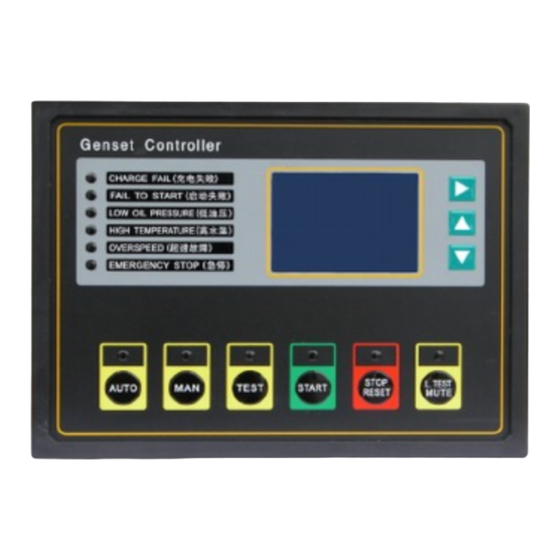
Page 5: Operation Panel
GU320a Controller Manual 3 Operation panel The whole Operation panel including three parts: LED display for measuring parameters、operating keys and running- status LED indicate。 LCD and its controlling keys LCD with 128×64mm lattice can display multiple lines of data information simultaneously and additive background-light function which make operators read information whenever day or night. -
Page 6: Installation
GU320a Controller Manual STOP/RESET key/LED Used to stop the generator by hand, when the controller set in “MAN” mode, this key could stop the generator. Press this key more than 2 seconds can release the fault stop lock if there is fault output. (When the controller performing the stop procedure, the indicator light above the key illuminate. -
Page 7: Control And Operation
GU320a Controller Manual Configuration for operating mode: Operation Description Press “AUTO” (for 2 seconds), the LED above illuminate, the controller then operating in “AUTO” Press“MAN”key(for 2 seconds), the LED on the button will illuminate, then the controller runs in this mode. - Page 8 GU320a Controller Manual When the remote control start signal valid, the start delay will active and begin to time. During the delay, if the remote start signal invalid, start delay will instantaneously stop, the controller will stop the start procedure, and return to original state“READY”...
-
Page 9: Measuring
GU320a Controller Manual The generator running normally, when press “STOP/RESET” key for a while in “MAN” mode, the controller begin cooling delay to stop as the Auto stop. Press the “STOP/RESET” key again for a while will disconnect the fuel valve, and the generator sets stop. -
Page 10: Fault Signal
GU320a Controller Manual Gen. KVArh As the frequency measuring is from L1 phase of the generator, ensure no fault with this part before use. 6.2 Other measuring data Oil pressure(KPa) Obtain the data from an external sensor Obtain the data from an external sensor Coolant temperature(℃)... -
Page 11: Parameters Configuration
GU320a Controller Manual Low Oil Pressure After the safety-on time-delay timeout, the controller detects the oil pressure switch closed, the engine stop instantaneously, and the LCD display “ALARM: LOW OILPRESS”, the fault indicator light “LOW OIL PRESSURE”, the buzzer warn. - Page 12 GU320a Controller Manual V Low Alarm AC45~20000V 0 (no setting) V Low preALM 198V AC45~20000V 0 (no setting) V High preALM 253V AC45~20000V 29999 (no setting) 29999 V High Alarm AC45~20000V 29999 (no setting) I High preALM 9999A 0~9999A 9999 (no setting)
-
Page 13: Lcd And Menu System
GU320a Controller Manual Datcon 5 bar Murphy 7 bar CMB 812 KP-YV01 User define Temperature sensor Type NOT USE VDO 120 degrees C Datcon high Datcon low Murphy Commis TS120 KP-T01 User define 9 LCD and menu system Display several lines of information at the same time according to the 128×64 lattice. LCD has background light. - Page 14 GU320a Controller Manual U=0V I=0A P=0kW F=0Hz SP=1500rpm OP=475kPa The current and voltage in this page is the average of the three phase. TEMP=80℃ Bat=25.4V V1=220V U12=380V I1=0A A1=0kVA P1=0kW PF1=1.00 Press “ ”or“ ” to switch pages Q1=0kVAr V2=220V...
-
Page 15: Communication
GU320a Controller Manual 3.ENGINE Press “ ”three times then press “ ”, then the LCD display: 0.QUIT 9. Crank attempt=3 Press “ ”nine times and then press “ ”, the LCD will display: 9. Crank attempt Press “ ”will indicate to enter password, enter the password: “... - Page 16 GU320a Controller Manual 100% Remote control function Covering the whole control function of panel. 10.2 CI485 Communication Link (Controller with RS485 com and CI48A accessory), more details please refer to the following wiring diagram: Tra n sfo rm te rm in a l...
- Page 17 GU320a Controller Manual The controller with RS485 communication interface, which allows connect at least 255 same serial controllers to the same communication line. And each equipment has sole ID No. To switch PC or MODEM, you need to collocate another RS485/RS232 converter. Typical wiring diagram as below:...
- Page 18 GU320a Controller Manual 10.3 Central Pick-up Control Unit Communication Protocols RS485 mechanism is a kind of network form by character signal between the computer and hardware device. Controller working baud rate is 9600-Baud, communication protocol is When it is MODBUS-RTU.
- Page 19 GU320a Controller Manual $1020 Alarm Alarm code 03: diesel engine stop 04: diesel engine start 05: Test state $1021 06: Man mode 07: Auto mode 08: Reset $1022 Product serial number $2001 Comm Address $2002 Language $2003 $2004 unit:V V Low Alarm $2005 unit:V...
-
Page 20: Preparations
GU320a Controller Manual $2030 RUNHr unit:HOUR $2031 Ext.Alarm mode $2032 Ext.Analog unit:0 - V / 1 - % calibration $2040 calibration $2041 calibration $2042 calibration $2043 calibration $2044 calibration $2045 Oil pressure calibration $2046 Temperature calibration $2047 Battery voltage calibration... -
Page 21: Troubleshooting
GU320a Controller Manual After the power supply is available, set the controller to MAN mode, the LED above the MAN key on. Now, calculate the measuring input frequency of the speed sensor first according to the rated rotating speed and number of tooth of the engine flywheel. - Page 22 GU320a Controller Manual mode, remote voltage, you need to check up the relative fuse. If the voltage is low, you need control start input to charge the battery additionally. Until the battery capacity full, you may signal is valid. In restart again.
- Page 23 GU320a Controller Manual 5. When the diesel running, you need to adjust the speed of diesel. 6. Please refer to the《Diesel Manual》for further details. Breaking the load adding to the AC generator. After the generator stop, you need to eliminate the fault and reset the “Genset” again..
Need help?
Do you have a question about the GU320a and is the answer not in the manual?
Questions and answers