Table of Contents
Advertisement
The information in this manual is proprietary and confidential to RFL Electronics Inc.
Any reproduction or distribution of this manual, in whole or part, is expressly
prohibited, unless written permission is given by RFL Electronics Inc.
This manual has been compiled and checked for accuracy. The information in this
manual does not constitute a warranty of performance. RFL Electronics Inc. reserves
the right to revise this manual and make changes to its contents from time to time. We
assume no liability for losses incurred as a result of out-of-date or incorrect information
contained in this manual.
Note: This product is covered by US Patent number 7,061,905
IMUX 2000E1
July 22, 2008
B e c a u s e R F L ™ a n d H u b b e l l ® h a v e a p o l i c y o f c o n t i n u o u s p r o d u c t i mp r o v e me n t , we r e s e r v e t h e r i g h t t o c h a n g e d e s i g n s a n d s p e c i fi c a t i o n s wi t h o u t n o t i c e .
RFL Electronics, Inc.
INSTRUCTION MANUAL
IMUX 2000
Intelligent E1 Multiplexer
With Redundant Capability
NOTICE
RFL Electronics Inc.
353 Powerville Road ● Boonton Twp., NJ 07005-9151 USA
Tel: 973.334.3100 ● Fax: 973.334.3863
Email:
sales@rflelect.com
Publication Number MC 2000CM4-E1
Printed in U.S.A.
Revised July 22, 2008
●
www.rflelect.com
i
RFL Electronics Inc.
973.334.3100
Advertisement
Table of Contents

Subscribe to Our Youtube Channel
Related Manuals for RFL IMUX 2000


Summary of Contents for RFL IMUX 2000
- Page 1 With Redundant Capability NOTICE The information in this manual is proprietary and confidential to RFL Electronics Inc. Any reproduction or distribution of this manual, in whole or part, is expressly prohibited, unless written permission is given by RFL Electronics Inc.
-
Page 2: Warranty Statement
RFL Customer Service facility in Boonton , New Jersey. RFL warrants product repair from five-years from the date of repair or the balance of the original factory warranty, whichever is longer. - Page 3 Read the safety summary on the reverse of this page IMUX 2000E1 RFL Electronics Inc. July 22, 2008 973.334.3100 B e c a u s e R F L ™ a n d H u b b e l l ® h a v e a p o l i c y o f c o n t i n u o u s p r o d u c t i mp r o v e me n t , we r e s e r v e t h e r i g h t t o c h a n g e d e s i g n s a n d s p e c i fi c a t i o n s wi t h o u t n o t i c e .
-
Page 4: Safety Summary
Failure to comply with these precautions, or with specific warnings elsewhere in this manual, violates safety standards of design, manufacture, and intended use of this product. RFL Electronics Inc. assumes no liability for failure to comply with these requirements. - Page 5 WARNING YOUR IMUX 2000 TERMINAL MAY BE EQUIPPED WITH FIBER OPTIC INPUT/OUTPUT MODULES THAT HAVE FIBER OPTIC EMITTER HEADS. FIBER OPTIC EMITTER HEADS USE A LASER LIGHT SOURCE THAT PRODUCE INVISIBLE RADIATION. FIBER OPTIC COMMUNICATION SYSTEMS INHERENTLY SAFE NORMAL OPERATION BECAUSE ALL RADIATION IS CONTAINED IN THE SYSTEM.
-
Page 6: Table Of Contents
LIST OF ILLUSTRATIONS............................ix LIST OF TABLES ..............................xii Section 1. PRODUCT INFORMATION ........................1 Section 2. FUNCTIONAL DESCRIPTION OF THE IMUX 2000 INTELLIGENT E1 MULTIPLEXER ....1 2.1 INTRODUCTION..............................1 2.2 MULTIPLEXER CONFIGURATIONS AND SYSTEMS..................1 2.3 MULTIPLEXER COMPONENTS ..........................6 2.4 MULTIPLEXER, FRONT-PANEL SWITCHES, INDICATORS, AND JACKS .......... - Page 7 DA-191B DA-291B IMUX 2000E1 RFL Electronics Inc. July 22, 2008 973.334.3100 B e c a u s e R F L ™ a n d H u b b e l l ® h a v e a p o l i c y o f c o n t i n u o u s p r o d u c t i mp r o v e me n t , we r e s e r v e t h e r i g h t t o c h a n g e d e s i g n s a n d s p e c i fi c a t i o n s wi t h o u t n o t i c e .
- Page 8 Section 20: APPLICATION NOTES (APPENDIX I) ....................1 Section 21: IMUX MODULE ADAPTERS (APPENDIX II)..................1 Section 22. ACCESSORY EQUIPMENT AND SYSTEM DRAWINGS..............1 IMUX 2000E1 RFL Electronics Inc. July 22, 2008 viii 973.334.3100 B e c a u s e R F L ™ a n d H u b b e l l ® h a v e a p o l i c y o f c o n t i n u o u s p r o d u c t i mp r o v e me n t , we r e s e r v e t h e r i g h t t o c h a n g e d e s i g n s a n d s p e c i fi c a t i o n s wi t h o u t n o t i c e .
- Page 9 Figure 2-25. Internal connections on the IMUX 2000 motherboard (fiber optic interface) ..........48 Figure 3-1. Top view of IMUX 2000 chassis showing locations of Standby and Main Common Modules......1 Figure 3-2. Functional block diagram, CM4 Common Module, Redundant Swap Control............. 3 Figure 3-3.
- Page 10 Figure 8-1. Rear view of Main or Repeater Shelf showing Bus Repeater Module and Repeater signal and power connectors..................................4 Figure 8-2. Terminal strip power connections for IMUX 2000 multiplexers with single power supply modules ....6 Figure 8-3. Teminal strip power connections for IMUX 2000 multiplexers with redundant power supply modules ..... 7 Figure 8-4.
- Page 11 Figure 11-1. Typical CM4 Optical Interface Adapter (OIA), rear panel view ................ 2 Figure 11-2. Block diagram, MA-217A Redundant I/O board....................5 Figure 11-3. Block diagram, Light Interface Board (LIB) for IMUX 2000 Optical Interface Adapters (OIAs)..... 6 Figure 12-1. E1 Frame................................1 Figure 12-2.
- Page 12 LIST OF TABLES Table 2-1. Characteristics of IMUX 2000 Module Adapters ....................18 Table 2-2. Characteristics of IMUX 2000 CM4 Optical Interface Adapters................. 24 Table 2-3. Characteristics of Power Supply Alarm I/O modules ..................27 Table 2-4. System status indicators and the ACO switch...................... 32 Table 2-5.
- Page 13 Table 10-3. Power Supply Alarm I/O Application Information....................9 Table 10-4. Power Supply and Power Supply Alarm I/O Schematics .................. 10 Table 11-1. Differences between IMUX 2000 Optical Interface Adapters ................3 Table 11-2. Acceptable received fiber optic power levels....................... 3 Table 21-1.
- Page 14 LIST OF EFFECTIVE PAGES When revisions are made to the IMUX 2000 Instruction Manual, the entire section where revisions were made is replaced. For the edition of this manual dated July 22, 2008, the sections are dated as follows: Front Matter...
-
Page 15: Section 1. Product Information
REVISION RECORD Description Date Approval 9-15-00 New Release – IMUX 2000 Instruction Manual (2000E1) updated to 9-29-00 IMUX 2000R Instruction Manual (MC2000R) with extensive revisions to incorporate CM3R module. (Derived from 2000E1, 3- 31-00) 4-10-01 Revised Sections: 0, 2, 6, 7, 8, 16, 17 & 18 in accordance with ECO 4-10-01 No. - Page 16 Revised in accordance with ECO No. 2000-389 (swap time) Sections 2, 6 and 8 IMUX 2000E1 RFL Electronics Inc. July 22, 2008 973.334.3100 B e c a u s e R F L ™ a n d H u b b e l l ® h a v e a p o l i c y o f c o n t i n u o u s p r o d u c t i mp r o v e me n t , we r e s e r v e t h e r i g h t t o c h a n g e d e s i g n s a n d s p e c i fi c a t i o n s wi t h o u t n o t i c e .
- Page 17 Revised VF-5C Product Information Sheets in accordance with CAR# 2000-0272 Revised NCM Product Information Sheets in accordance with CAR# 2000-0272 Added RFL SAG.MIB file to CD version of this Instruction Manual in accordance with CAR# C2000-0309 4-1-07 Incorporated Errata Sheet MC2000CM4-E1-006, 007, 008, 009 and 4-1-07 010.
- Page 18 This page intentionally left blank IMUX 2000E1 RFL Electronics Inc. July 22, 2008 xviii 973.334.3100 B e c a u s e R F L ™ a n d H u b b e l l ® h a v e a p o l i c y o f c o n t i n u o u s p r o d u c t i mp r o v e me n t , we r e s e r v e t h e r i g h t t o c h a n g e d e s i g n s a n d s p e c i fi c a t i o n s wi t h o u t n o t i c e .
- Page 19 Section 1. PRODUCT INFORMATION IMUX 2000E1 RFL Electronics Inc. April 1, 2007 (973) 334-3100 B e c a u s e R F L ™ a n d H u b b e l l ® h a v e a p o l i c y o f c o n t i n u o u s p r o d u c t i mp r o v e me n t , we r e s e r v e t h e r i g h t t o c h a n g e d e s i g n s a n d s p e c i fi c a t i o n s wi t h o u t n o t i c e .
- Page 20 This page intentionally left blank IMUX 2000E1 RFL Electronics Inc. April 1, 2007 (973) 334-3100 B e c a u s e R F L ™ a n d H u b b e l l ® h a v e a p o l i c y o f c o n t i n u o u s p r o d u c t i mp r o v e me n t , we r e s e r v e t h e r i g h t t o c h a n g e d e s i g n s a n d s p e c i fi c a t i o n s wi t h o u t n o t i c e .
- Page 21 Intelligent choice, the protection, video and ethernet applications. When com- IMUX 2000 Intelligent T1/E1 Multiplexer. bined with our IMUX 2000 8-Port DACS-R, the IMUX 2000 IMUX 2000 T1/E1 April 2007 B e c a u s e R F L ™ a n d H u b b e l l ® h a v e a p o l i c y o f c o n t i n u o u s p r o d u c t i mp r o v e me n t , we r e s e r v e t h e r i g h t t o c h a n g e d e s i g n s a n d s p e c i fi c a t i o n s wi t h o u t n o t i c e .
- Page 22 Trip and Video channel interfaces to meet most commu- • Speed nications requirements. The IMUX 2000 is designed to handle time sensitive ap- plications such as Protective Relaying. The Drop-and- • Fast Restoration Insert through-channel delay is less than 25 microsec- When applied to diverse communication routes, such as Ring onds.
- Page 23 That is why the IMUX 2000 T1/E1 Multiplexer, with its unique harsh environments design, is the preferred choice of com- munication for the Transportation Industry.
- Page 24 Point-to-Point, Star and Stand-Alone Linear topology over the SONET/SDH system. The IMUX 2000 carries RTU and phone circuits from several substations to the operations center. It also carries current differential relay data between substations. The IMUX 2000 carries roadside signals, transmission data from vehicle loop detectors, compressed digital video, camera control, toll collection information, status and alarm reporting, voice and data traffic signal controls back to the operations center.
-
Page 25: Technical Specifications
The chassis and channel modules shall meet require- ments of IEC 255-21-2 and IEC 255-21-1. IMUX 2000 T1/E1 April 2007 B e c a u s e R F L ™ a n d H u b b e l l ® h a v e a p o l i c y o f c o n t i n u o u s p r o d u c t i mp r o v e me n t , we r e s e r v e t h e r i g h t t o c h a n g e d e s i g n s a n d s p e c i fi c a t i o n s wi t h o u t n o t i c e . - Page 26 2W VF • Type I, II, III & V E & M signaling IMUX 2000 T1/E1 April 2007 B e c a u s e R F L ™ a n d H u b b e l l ® h a v e a p o l i c y o f c o n t i n u o u s p r o d u c t i mp r o v e me n t , we r e s e r v e t h e r i g h t t o c h a n g e d e s i g n s a n d s p e c i fi c a t i o n s wi t h o u t n o t i c e .
- Page 27 • Network password protection for added security Typical Network Management Screens IMUX 2000 T1/E1 April 2007 B e c a u s e R F L ™ a n d H u b b e l l ® h a v e a p o l i c y o f c o n t i n u o u s p r o d u c t i mp r o v e me n t , we r e s e r v e t h e r i g h t t o c h a n g e d e s i g n s a n d s p e c i fi c a t i o n s wi t h o u t n o t i c e .
- Page 28 April 2007 IMUX 2000 T1/E1 B e c a u s e R F L ™ a n d H u b b e l l ® h a v e a p o l i c y o f c o n t i n u o u s p r o d u c t i mp r o v e me n t , we r e s e r v e t h e r i g h t t o c h a n g e d e s i g n s a n d s p e c i fi c a t i o n s wi t h o u t n o t i c e .
-
Page 29: Section 2. Functional Description Of The Imux 2000 Intelligent E1 Multiplexer
IMUX 2000 Intelligent E1 Multiplexer. 2.2 MULTIPLEXER CONFIGURATIONS AND SYSTEMS The IMUX 2000 Intelligent E1 multiplexer can be configured as a terminal multiplexer or as a drop/insert multiplexer. Both of these configurations can be fitted with an electrical E1 interface or an optical E1 interface using a variety of interface adapters. - Page 30 Time slot 30 is used for fast reframe function, if enabled. See Section 12 for more information on E1 framing. IMUX 2000E1 RFL Electronics Inc. April 1, 2007 (973) 334-3100 B e c a u s e R F L ™ a n d H u b b e l l ® h a v e a p o l i c y o f c o n t i n u o u s p r o d u c t i mp r o v e me n t , we r e s e r v e t h e r i g h t t o c h a n g e d e s i g n s a n d s p e c i fi c a t i o n s wi t h o u t n o t i c e .
- Page 31 The RFL fast reframe uses time slot 30. If fast reframing is required in a network, all nodes should have fast reframing enabled, and time slot 30 will be reserved. If all nodes have fast reframe disabled, time slot 30 will be available for user payload data.
- Page 32 Figure 2-3. Drop/insert multiplexer (sample configuration) 2.2.3 POINT-TO-POINT SYSTEMS The simplest type of IMUX 2000 system configuration is a point-to-point system. A point-to-point system consists of two terminal multiplexers connected by a single E1 electrical or fiber optic circuit. (See Figure 2-4.) As the figure illustrates, the same payload circuits will appear at both ends of a point- to-point system.
- Page 33 LOCATION 1 LOCATION 2 IMUX 2000 TERMINAL IMUX 2000 TERMINAL MULTIPLEXER MULTIPLEXER E1 CIRCUIT D OW VOICE 1 VOICE 1 DATA 1 DATA 1 ORDER WIRE ORDER WIRE VOICE 2 VOICE 2 DATA 2 DATA 2 Figure 2-4. Point-to-point system (example)
-
Page 34: Multiplexer Components
2.3.1 MAIN SHELF The Main Shelf is the enclosure for the IMUX 2000 multiplexer. It has plug-in slots in the front for one main power supply and one optional redundant power supply. It also provides 18 physical slots for E1 common modules and channel modules. - Page 35 Drop and Insert Figure 2-6. Front view of main shelf IMUX 2000E1 RFL Electronics Inc. April 1, 2007 (973) 334-3100 B e c a u s e R F L ™ a n d H u b b e l l ® h a v e a p o l i c y o f c o n t i n u o u s p r o d u c t i mp r o v e me n t , we r e s e r v e t h e r i g h t t o c h a n g e d e s i g n s a n d s p e c i fi c a t i o n s wi t h o u t n o t i c e .
- Page 36 Module Adapters. (See paragraph 2.3.8 for more information.) IMUX 2000E1 RFL Electronics Inc. April 1, 2007 (973) 334-3100 B e c a u s e R F L ™ a n d H u b b e l l ® h a v e a p o l i c y o f c o n t i n u o u s p r o d u c t i mp r o v e me n t , we r e s e r v e t h e r i g h t t o c h a n g e d e s i g n s a n d s p e c i fi c a t i o n s wi t h o u t n o t i c e .
- Page 37 REPEATER POWER SUPPLIES Figure 2-7. Front view of multiple repeater shelves IMUX 2000E1 RFL Electronics Inc. April 1, 2007 (973) 334-3100 B e c a u s e R F L ™ a n d H u b b e l l ® h a v e a p o l i c y o f c o n t i n u o u s p r o d u c t i mp r o v e me n t , we r e s e r v e t h e r i g h t t o c h a n g e d e s i g n s a n d s p e c i fi c a t i o n s wi t h o u t n o t i c e .
- Page 38 CM4 Common Modules. In redundant applications, each IMUX 2000 terminal multiplexer contains two CM4 Common Modules, while a drop/insert multiplexer contains four CM4 Common Modules. The CM4 is the standard E1 Common Module for the IMUX 2000. It provides the following sixteen operational functions: CM4 Operational Functions See Paragraph 1.
- Page 39 (RS-422) CM4 Status and Control Bus Figure 2-8. Functional diagram, CM4 Common Module, Communications Control IMUX 2000E1 RFL Electronics Inc. April 1, 2007 2-11 (973) 334-3100 B e c a u s e R F L ™ a n d H u b b e l l ® h a v e a p o l i c y o f c o n t i n u o u s p r o d u c t i mp r o v e me n t , we r e s e r v e t h e r i g h t t o c h a n g e d e s i g n s a n d s p e c i fi c a t i o n s wi t h o u t n o t i c e .
- Page 40 Bus signals include demultiplexed channel data, demultiplexer synchronization status, and synchronization signals necessary for proper decoding by the channel modules. IMUX 2000E1 RFL Electronics Inc. April 1, 2007 2-12 (973) 334-3100...
- Page 41 LOOP is the primary timing setting. Refer to Application Notes (Section 20) for suggested settings of fallback timing. IMUX 2000E1 RFL Electronics Inc. April 1, 2007 2-13 (973) 334-3100...
- Page 42 Front Panel Interface appear in Section 4 of this manual. RS-232 Interface - The IMUX 2000 multiplexer can be set up and monitored from a data terminal connected to its RS-232 port. This connection can be made locally at the controlled multiplexer shelf, or remotely at any other node of the E1 network using the NCM (Network Communication Module) module.
- Page 43 When Fast Reframe is set to off, the system is in normal reframing mode. Normal reframing mode is usually used for voice communications, however with data communications fast reframing is usually used. IMUX 2000E1 RFL Electronics Inc. April 1, 2007 2-15 (973) 334-3100...
- Page 44 Count of received bipolar violation Count of received bit error Count of received multiframe out of sync IMUX 2000E1 RFL Electronics Inc. April 1, 2007 2-16 (973) 334-3100 B e c a u s e R F L ™ a n d H u b b e l l ® h a v e a p o l i c y o f c o n t i n u o u s p r o d u c t i mp r o v e me n t , we r e s e r v e t h e r i g h t t o c h a n g e d e s i g n s a n d s p e c i fi c a t i o n s wi t h o u t n o t i c e .
- Page 45 2.3.3.11 and Section 5 for more information. 2.3.3.13 Download Function The download function allows a user to update CM4 application code by using a terminal emulation package containing the XMODEM transfer protocol.. Contact RFL customer service for more information. IMUX 2000E1 RFL Electronics Inc.
- Page 46 2.3.4.1 Electrical Interface Adapters Electrical interface adapters are used to connect the IMUX 2000 electrically to a E1 network. There are four types of electrical interface adapters available. These are the MA-271, MA-278, MA-270R and MA-275R.
- Page 47 E1 OUT E1 OUT Figure 2-10. MA-271, MA278, MA-270R and MA-275R Module Adapters, rear panel views IMUX 2000E1 RFL Electronics Inc. April 1, 2007 2-19 (973) 334-3100 B e c a u s e R F L ™ a n d H u b b e l l ® h a v e a p o l i c y o f c o n t i n u o u s p r o d u c t i mp r o v e me n t , we r e s e r v e t h e r i g h t t o c h a n g e d e s i g n s a n d s p e c i fi c a t i o n s wi t h o u t n o t i c e .
- Page 48 RS232RXD RS-232 Figure 2-11. MA-271 pinouts IMUX 2000E1 RFL Electronics Inc. April 1, 2007 2-20 (973) 334-3100 B e c a u s e R F L ™ a n d H u b b e l l ® h a v e a p o l i c y o f c o n t i n u o u s p r o d u c t i mp r o v e me n t , we r e s e r v e t h e r i g h t t o c h a n g e d e s i g n s a n d s p e c i fi c a t i o n s wi t h o u t n o t i c e .
- Page 49 RS232TXD RS232RXD Figure 2-12. MA-278 pinouts IMUX 2000E1 RFL Electronics Inc. April 1, 2007 2-21 (973) 334-3100 B e c a u s e R F L ™ a n d H u b b e l l ® h a v e a p o l i c y o f c o n t i n u o u s p r o d u c t i mp r o v e me n t , we r e s e r v e t h e r i g h t t o c h a n g e d e s i g n s a n d s p e c i fi c a t i o n s wi t h o u t n o t i c e .
- Page 50 E1-OUT- E1-OUT+ Figure 2-13. MA-270R pinouts IMUX 2000E1 RFL Electronics Inc. April 1, 2007 2-22 (973) 334-3100 B e c a u s e R F L ™ a n d H u b b e l l ® h a v e a p o l i c y o f c o n t i n u o u s p r o d u c t i mp r o v e me n t , we r e s e r v e t h e r i g h t t o c h a n g e d e s i g n s a n d s p e c i fi c a t i o n s wi t h o u t n o t i c e .
- Page 51 SCB STROBE A SHIELD Figure 2-14. MA-275R pinouts IMUX 2000E1 RFL Electronics Inc. April 1, 2007 2-23 (973) 334-3100 B e c a u s e R F L ™ a n d H u b b e l l ® h a v e a p o l i c y o f c o n t i n u o u s p r o d u c t i mp r o v e me n t , we r e s e r v e t h e r i g h t t o c h a n g e d e s i g n s a n d s p e c i fi c a t i o n s wi t h o u t n o t i c e .
- Page 52 2.3.4.2 Optical Interface Adapters (OIAs) Optical interface adapters are used to connect the IMUX 2000 to a E1 network using fiber optic cables. There are five types of CM4 optical interface adapters available which can be used for redundant or non-redundant applications.
- Page 53 TIMOUT- TIMOUT+ Figure 2-15. Typical CM4 Optical Interface Adapter (OIA), rear panel view IMUX 2000E1 RFL Electronics Inc. April 1, 2007 2-25 (973) 334-3100 B e c a u s e R F L ™ a n d H u b b e l l ® h a v e a p o l i c y o f c o n t i n u o u s p r o d u c t i mp r o v e me n t , we r e s e r v e t h e r i g h t t o c h a n g e d e s i g n s a n d s p e c i fi c a t i o n s wi t h o u t n o t i c e .
-
Page 54: Power Supply Modules
The Main Shelf can contain one or two power supplies with the same capacity. A functional block diagram of the IMUX 2000 Power Supply and the Power Supply Alarm I/O module appears in Figure 2-16. - Page 55 2.3.6 POWER SUPPLY ALARM I/O MODULE There are six types of Power Supply Alarm I/O modules that can be used with the IMUX 2000 Multiplexer chassis. These modules can also be used in the ILS and DACS chassis if required. Some of the characteristics of these modules are listed in Table 2-3.
- Page 56 P.S. MAIN P.S. REDUNDANT Figure 2-17. Typical Power Supply Alarm I/O module, rear panel view IMUX 2000E1 RFL Electronics Inc. April 1, 2007 2-28 (973) 334-3100 B e c a u s e R F L ™ a n d H u b b e l l ® h a v e a p o l i c y o f c o n t i n u o u s p r o d u c t i mp r o v e me n t , we r e s e r v e t h e r i g h t t o c h a n g e d e s i g n s a n d s p e c i fi c a t i o n s wi t h o u t n o t i c e .
- Page 57 IMUX 2000 channel module configuration guidelines appears in Section 4 of this manual. Instruction Data sheets for all IMUX 2000 channel modules appear in Sections 14 through 19 of this manual.
-
Page 58: Multiplexer, Front-Panel Switches, Indicators, And Jacks
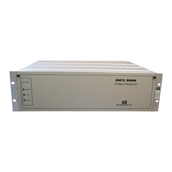
2.4 MULTIPLEXER, FRONT-PANEL SWITCHES, INDICATORS, AND JACKS Figure 2-19 is a front view of the IMUX 2000 terminal multiplexer with its front door open. A drop/insert multiplexer will look the same, except for the addition of a second CM4 Common Module. - Page 59 2.4.1 SYSTEM STATUS INDICATORS AND THE ACO SWITCH When the IMUX 2000 Main Shelf front door is closed, four LED indicators are visible. These LEDs are labeled: POWER, NORMAL, ALERT, and ALARM, as shown in Figure 2-20, and indicate the operational status of the multiplexer at a glance.
- Page 60 An unframed "all ones" is a E1 Alarm Indication Signal (AIS). This indicator also lights briefly at power-on. Effective March 06 IMUX 2000E1 RFL Electronics Inc. April 1, 2007 2-32 (973) 334-3100 B e c a u s e R F L ™ a n d H u b b e l l ® h a v e a p o l i c y o f c o n t i n u o u s p r o d u c t i mp r o v e me n t , we r e s e r v e t h e r i g h t t o c h a n g e d e s i g n s a n d s p e c i fi c a t i o n s wi t h o u t n o t i c e .
- Page 61 T1 or E1 encoded data. Monitoring the T1 or E1 signals via the test jacks labeled “T1 OUT MON” or “T1 IN MON” on the front of the CM4 requires an RFL CMI Converter. Refer to the CMI Converter Instruction Data Sheet for additional information.
- Page 62 NOTE: When you are facing the front of the multiplexer, the "up" position of each toggle switch or slide switch is to the right, and its "down" position is to the left. IMUX 2000E1 RFL Electronics Inc. April 1, 2007 2-34 (973) 334-3100 B e c a u s e R F L ™...
- Page 63 0x06 (not used in E1) 0x07 (not used in E1) Notes: (1) Active on terminal multiplexers only. (2) Active on drop/insert multiplexers only. IMUX 2000E1 RFL Electronics Inc. April 1, 2007 2-35 (973) 334-3100 B e c a u s e R F L ™ a n d H u b b e l l ® h a v e a p o l i c y o f c o n t i n u o u s p r o d u c t i mp r o v e me n t , we r e s e r v e t h e r i g h t t o c h a n g e d e s i g n s a n d s p e c i fi c a t i o n s wi t h o u t n o t i c e .
- Page 64 Rcpu Reset cpu IMUX 2000E1 RFL Electronics Inc. April 1, 2007 2-36 (973) 334-3100 B e c a u s e R F L ™ a n d H u b b e l l ® h a v e a p o l i c y o f c o n t i n u o u s p r o d u c t i mp r o v e me n t , we r e s e r v e t h e r i g h t t o c h a n g e d e s i g n s a n d s p e c i fi c a t i o n s wi t h o u t n o t i c e .
- Page 65 E1 signal timing: GREEN: The transmitter and receiver timing clocks are locked. RED: The transmitter and receiver timing clocks are not locked. IMUX 2000E1 RFL Electronics Inc. April 1, 2007 2-37 (973) 334-3100 B e c a u s e R F L ™ a n d H u b b e l l ® h a v e a p o l i c y o f c o n t i n u o u s p r o d u c t i mp r o v e me n t , we r e s e r v e t h e r i g h t t o c h a n g e d e s i g n s a n d s p e c i fi c a t i o n s wi t h o u t n o t i c e .
- Page 66 Figure 2-21. Overview of CM4 Groups and Functions IMUX 2000E1 RFL Electronics Inc. April 1, 2007 2-38 (973) 334-3100 B e c a u s e R F L ™ a n d H u b b e l l ® h a v e a p o l i c y o f c o n t i n u o u s p r o d u c t i mp r o v e me n t , we r e s e r v e t h e r i g h t t o c h a n g e d e s i g n s a n d s p e c i fi c a t i o n s wi t h o u t n o t i c e .
- Page 67 External Timing Mode indicator (green). Lights when the CM4 E1 transmitter is externally timed. Blinks when EXT is the primary timing mode, but the CM4 module is in fallback timing mode. IMUX 2000E1 RFL Electronics Inc. April 1, 2007 2-39 (973) 334-3100...
- Page 68 When frame format is set to SF, this indicator flashes once each time a frame error is detected, and remains on continuously above a random bit error ratio of about 10 -3 . IMUX 2000E1 RFL Electronics Inc. April 1, 2007 2-40 (973) 334-3100...
- Page 69 Out-Of-Frame indicator (red). Lights when the CM4 E1 receiver is not in frame synchronization. This can indicate either a high bit error ratio, or improper CM4 configuration. IMUX 2000E1 RFL Electronics Inc. April 1, 2007 2-41 (973) 334-3100 B e c a u s e R F L ™ a n d H u b b e l l ® h a v e a p o l i c y o f c o n t i n u o u s p r o d u c t i mp r o v e me n t , we r e s e r v e t h e r i g h t t o c h a n g e d e s i g n s a n d s p e c i fi c a t i o n s wi t h o u t n o t i c e .
-
Page 70: Multiplexer, Rear Panel Connections
ALARM relay COM contact (common). ALARM NC ALARM relay N.C. contact (normally-closed). IMUX 2000E1 RFL Electronics Inc. April 1, 2007 2-42 (973) 334-3100 B e c a u s e R F L ™ a n d H u b b e l l ® h a v e a p o l i c y o f c o n t i n u o u s p r o d u c t i mp r o v e me n t , we r e s e r v e t h e r i g h t t o c h a n g e d e s i g n s a n d s p e c i fi c a t i o n s wi t h o u t n o t i c e . - Page 71 E1 OUT P.S. REDUNDANT Figure 2-22. Rear panel connectors, Main Shelf equipped with MA-270R Module Adapters IMUX 2000E1 RFL Electronics Inc. April 1, 2007 2-43 (973) 334-3100 B e c a u s e R F L ™ a n d H u b b e l l ® h a v e a p o l i c y o f c o n t i n u o u s p r o d u c t i mp r o v e me n t , we r e s e r v e t h e r i g h t t o c h a n g e d e s i g n s a n d s p e c i fi c a t i o n s wi t h o u t n o t i c e .
- Page 72 EXT TMG P.S. REDUNDANT Figure 2-23. Rear panel connectors, Main Shelf equipped with Optical Interface Adapters. IMUX 2000E1 RFL Electronics Inc. April 1, 2007 2-44 (973) 334-3100 B e c a u s e R F L ™ a n d H u b b e l l ® h a v e a p o l i c y o f c o n t i n u o u s p r o d u c t i mp r o v e me n t , we r e s e r v e t h e r i g h t t o c h a n g e d e s i g n s a n d s p e c i fi c a t i o n s wi t h o u t n o t i c e .
- Page 73 5 and 12 Timing Out; a balanced RS-422 output from the corresponding CM4 that may be used as an external E1 timing source by other IMUX 2000 multiplexers. 6 and 13 Timing In; a balanced 2.048-mHz RS-422 input to the corresponding CM4 that may be connected to an external E1 timing source.
-
Page 74: Multiplexer, Setup Jumpers And Dip Switches
UP (off) UP (off) SPARE IMUX 2000E1 RFL Electronics Inc. April 1, 2007 2-46 (973) 334-3100 B e c a u s e R F L ™ a n d H u b b e l l ® h a v e a p o l i c y o f c o n t i n u o u s p r o d u c t i mp r o v e me n t , we r e s e r v e t h e r i g h t t o c h a n g e d e s i g n s a n d s p e c i fi c a t i o n s wi t h o u t n o t i c e . -
Page 75: Multiplexer, Internal Connections On The Motherboard
2.7 MULTIPLEXER, INTERNAL CONNECTIONS ON THE MOTHERBOARD Figure 2-24 is a simplified functional diagram of the internal connections of an IMUX 2000 Multiplexer using an electrical E1 interface. Figure 2-25 shows the connections of an IMUX 2000 Multiplexer using an fiber optic interface. - Page 76 1. ALL CONNECTIONS TO MODULE ADAPTERS AND CHANNEL MODULES ARE MADE ON PINS 15 THROUGH 32 2. THE SECOND COMMON MODULE AND MA-210 MODULE ADAPTER ARE USED IN DROP/INSERT MULTIPLEXERS ONLY. Figure 2-24. Internal connections on the IMUX 2000 motherboard (electrical E1 interface) RS-232...
-
Page 77: Section 3. Cm4 Common Module Redundant Protection Mode
Main Common Common Module Module Figure 3-1. Top view of IMUX 2000 chassis showing locations of Standby and Main Common Modules. IMUX 2000E1 RFL Electronics Inc. January 23, 2004 (973) 334-3100 B e c a u s e R F L ™ a n d H u b b e l l ® h a v e a p o l i c y o f c o n t i n u o u s p r o d u c t i mp r o v e me n t , we r e s e r v e t h e r i g h t t o c h a n g e d e s i g n s a n d s p e c i fi c a t i o n s wi t h o u t n o t i c e . - Page 78 • The CM4 Main/Standby pairs in a Drop-and-Insert are independent. The state and actions of one pair does not affect the other pair. IMUX 2000E1 RFL Electronics Inc. January 23, 2004 (973) 334-3100 B e c a u s e R F L ™ a n d H u b b e l l ® h a v e a p o l i c y o f c o n t i n u o u s p r o d u c t i mp r o v e me n t , we r e s e r v e t h e r i g h t t o c h a n g e d e s i g n s a n d s p e c i fi c a t i o n s wi t h o u t n o t i c e .
- Page 79 CM4 Status and Control Bus Figure 3-2. Functional block diagram, CM4 Common Module, Redundant Swap Control IMUX 2000E1 RFL Electronics Inc. January 23, 2004 (973) 334-3100 B e c a u s e R F L ™ a n d H u b b e l l ® h a v e a p o l i c y o f c o n t i n u o u s p r o d u c t i mp r o v e me n t , we r e s e r v e t h e r i g h t t o c h a n g e d e s i g n s a n d s p e c i fi c a t i o n s wi t h o u t n o t i c e .
- Page 80 There is no automatic return to Main. IMUX 2000E1 RFL Electronics Inc. January 23, 2004 (973) 334-3100 B e c a u s e R F L ™ a n d H u b b e l l ® h a v e a p o l i c y o f c o n t i n u o u s p r o d u c t i mp r o v e me n t , we r e s e r v e t h e r i g h t t o c h a n g e d e s i g n s a n d s p e c i fi c a t i o n s wi t h o u t n o t i c e .
- Page 81 ACTIVE Figure 3-4. CM4 Module Swapping flowchart, Forced Swap IMUX 2000E1 RFL Electronics Inc. January 23, 2004 (973) 334-3100 B e c a u s e R F L ™ a n d H u b b e l l ® h a v e a p o l i c y o f c o n t i n u o u s p r o d u c t i mp r o v e me n t , we r e s e r v e t h e r i g h t t o c h a n g e d e s i g n s a n d s p e c i fi c a t i o n s wi t h o u t n o t i c e .
- Page 82 30 seconds after the command is issued. IMUX 2000E1 RFL Electronics Inc. January 23, 2004 (973) 334-3100 B e c a u s e R F L ™ a n d H u b b e l l ® h a v e a p o l i c y o f c o n t i n u o u s p r o d u c t i mp r o v e me n t , we r e s e r v e t h e r i g h t t o c h a n g e d e s i g n s a n d s p e c i fi c a t i o n s wi t h o u t n o t i c e .
- Page 83 • No independent communication with outside. IMUX 2000E1 RFL Electronics Inc. January 23, 2004 (973) 334-3100 B e c a u s e R F L ™ a n d H u b b e l l ® h a v e a p o l i c y o f c o n t i n u o u s p r o d u c t i mp r o v e me n t , we r e s e r v e t h e r i g h t t o c h a n g e d e s i g n s a n d s p e c i fi c a t i o n s wi t h o u t n o t i c e .
- Page 84 The Current state of a CM4 Common Module can also be determined over a network management link (RS-232 or NCM[E1]). IMUX 2000E1 RFL Electronics Inc. January 23, 2004 (973) 334-3100 B e c a u s e R F L ™ a n d H u b b e l l ® h a v e a p o l i c y o f c o n t i n u o u s p r o d u c t i mp r o v e me n t , we r e s e r v e t h e r i g h t t o c h a n g e d e s i g n s a n d s p e c i fi c a t i o n s wi t h o u t n o t i c e .
- Page 85 LED INDICATORS Figure 3-6. Front panel mode slide switch IMUX 2000E1 RFL Electronics Inc. January 23, 2004 (973) 334-3100 B e c a u s e R F L ™ a n d H u b b e l l ® h a v e a p o l i c y o f c o n t i n u o u s p r o d u c t i mp r o v e me n t , we r e s e r v e t h e r i g h t t o c h a n g e d e s i g n s a n d s p e c i fi c a t i o n s wi t h o u t n o t i c e .
- Page 86 “SWCH” group. The allowed selections are “MAIN” (activate Main Module), “STBY” (activate Standby Module) or “AUTO” (allow automatic operation). See Table 2-8 and Figure 2-22. An equivalent selection can be made via NMS by setting the SWITCH parameter. IMUX 2000E1 RFL Electronics Inc. January 23, 2004 3-10 (973) 334-3100...
- Page 87 Finally, it is important to remember that all controlling methods must be individually returned to AUTO for automatic operation. This includes both the front-panel mode slide switch and the SWITCH configuration parameter, as well as MAIN=ON. IMUX 2000E1 RFL Electronics Inc. January 23, 2004 3-11 (973) 334-3100...
- Page 88 IMUX 2000E1 RFL Electronics Inc. January 23, 2004 3-12 (973) 334-3100 B e c a u s e R F L ™ a n d H u b b e l l ® h a v e a p o l i c y o f c o n t i n u o u s p r o d u c t i mp r o v e me n t , we r e s e r v e t h e r i g h t t o c h a n g e d e s i g n s a n d s p e c i fi c a t i o n s wi t h o u t n o t i c e .
- Page 89 20 seconds. Therefore, inactive module should not be activated for 20 seconds after any configuration changes. The above procedure pertains to TERM as well as both DI-A and DI-B Redundant Common Modules. IMUX 2000E1 RFL Electronics Inc. January 23, 2004 3-13 (973) 334-3100...
- Page 90 New settings related to redundant operation (SWITCH, MAIN, CSU, etc.) are reported in response to the second-level inquiry: <address>:<subaddress>:CONFIG2?:; • Forced-switch configuration parameters. Using a network management link, the forced-switch parameter can be programmed by RFL NMS or with SCL commands in format: <address>:<subaddress>:SET:SWITCH=[MAIN,STANDBY,AUTO]; Main On/Off parameter is set by: <address>:<subaddress>:SET:MAIN=[OFF,ON];...
-
Page 91: Section 4. Channel Modules Overview
Section 4. CHANNEL MODULES OVERVIEW 4.1 CHANNEL MODULE TYPES There are several types of channel modules which can be used with the IMUX 2000 Multiplexer. Detailed information on each channel module type appears in the following sections of this manual:... -
Page 92: Physical Slots And Time Slots
(or group of time slots) within a E1 circuit, regardless of its physical location (slot) on an IMUX 2000 equipment shelf. This makes it important to distinguish physical slots on IMUX 2000 multiplexer shelves from time slots within the E1 circuit. In most cases, they are not directly related. - Page 93 E1 CIRCUIT MODULES T DATA R DATA MA-270R MA-270R “A” BUS CLOCK IMUX 2000 IMUX 2000 (DI-B) (TERM or DI-A a. Channel modules set to transmit in Direction A, receive from Direction B. Transmit “A” Direction Transmit “B” Direction CLOCK “B”...
- Page 94 For example, in Figure 4-2, the transmit-receive (T/R) and transmit-only (T) channel modules in multipleers #1 and #2 that are configured to transmit in the “A” direction, actually transmit in opposite directions over the same E1 facility. IMUX 2000 IMUX 2000 IMUX 2000...
-
Page 95: Channel Module Configuration Guidelines
(electrical E1 interface) or OIAs, 2 slots in terminal mode, are reserved for Common Modules. The remaining 14 physical slots (Slots 5 through 18), are available for channel modules. One Expansion Shelf may be added to each IMUX 2000 Main Shelf. An Expansion Shelf provides physical slots for up to 18 additional channel modules. -
Page 96: Power Available For Channel Modules
BRM, but is simply passed from backplane to backplane. Refer to paragraph 2.3.2 for more information on the Repeater Shelf. IMUX 2000E1 RFL Electronics Inc. January 1, 2008 (973) 334-3100 B e c a u s e R F L ™ a n d H u b b e l l ® h a v e a p o l i c y o f c o n t i n u o u s p r o d u c t i mp r o v e me n t , we r e s e r v e t h e r i g h t t o c h a n g e d e s i g n s a n d s p e c i fi c a t i o n s wi t h o u t n o t i c e . -
Page 97: Determining Channel Module Power Requirements
To determine how much power the channel modules in a multiplexer shelf will draw, refer to Tables 4-1 and 4-2. The current draw at +5V, +15V and –15V for all IMUX 2000 channel modules, Common Modules, OIAs and Module Adapters are given in these tables. - Page 98 If current draw exceeds 4.0 Amps from +5V supply, 0.75 Amps from +15V supply, or 0.75 Amps from –15V supply, additional power supply capacity is required. IMUX 2000E1 RFL Electronics Inc. January 1, 2008 (973) 334-3100 B e c a u s e R F L ™ a n d H u b b e l l ® h a v e a p o l i c y o f c o n t i n u o u s p r o d u c t i mp r o v e me n t , we r e s e r v e t h e r i g h t t o c h a n g e d e s i g n s a n d s p e c i fi c a t i o n s wi t h o u t n o t i c e .
- Page 99 If total power consumption exceeds 50 watts, additional power supply capacity is required. IMUX 2000E1 RFL Electronics Inc. January 1, 2008 (973) 334-3100 B e c a u s e R F L ™ a n d H u b b e l l ® h a v e a p o l i c y o f c o n t i n u o u s p r o d u c t i mp r o v e me n t , we r e s e r v e t h e r i g h t t o c h a n g e d e s i g n s a n d s p e c i fi c a t i o n s wi t h o u t n o t i c e .
- Page 100 This page intentionally left blank IMUX 2000E1 RFL Electronics Inc. January 1, 2008 4-10 (973) 334-3100 B e c a u s e R F L ™ a n d H u b b e l l ® h a v e a p o l i c y o f c o n t i n u o u s p r o d u c t i mp r o v e me n t , we r e s e r v e t h e r i g h t t o c h a n g e d e s i g n s a n d s p e c i fi c a t i o n s wi t h o u t n o t i c e .
-
Page 101: Section 5. Setup And Configuration
Section 5. SETUP AND CONFIGURATION 5.1 INTRODUCTION This section contains information on how to set up the IMUX 2000 and operate it under local control. 5.2 CM4 MODES A CM4 module can operate in one of three modes: TERM Terminal (terminal multiplexer only) - Page 102 SPARE Figure 5-1. Location and use of setup jumpers on the MA-271 and MA-278 Module Adapters. IMUX 2000E1 RFL Electronics Inc. January 1, 2008 (973) 334-3100 B e c a u s e R F L ™ a n d H u b b e l l ® h a v e a p o l i c y o f c o n t i n u o u s p r o d u c t i mp r o v e me n t , we r e s e r v e t h e r i g h t t o c h a n g e d e s i g n s a n d s p e c i fi c a t i o n s wi t h o u t n o t i c e .
- Page 103 Figure 5-2. Location and use of setup jumpers on the MA-270R Module Adapter. IMUX 2000E1 RFL Electronics Inc. January 1, 2008 (973) 334-3100 B e c a u s e R F L ™ a n d H u b b e l l ® h a v e a p o l i c y o f c o n t i n u o u s p r o d u c t i mp r o v e me n t , we r e s e r v e t h e r i g h t t o c h a n g e d e s i g n s a n d s p e c i fi c a t i o n s wi t h o u t n o t i c e .
- Page 104 MA-270R. Figure 5-3. Location and use of setup jumpers on MA-275R Module Adapter. IMUX 2000E1 RFL Electronics Inc. January 1, 2008 (973) 334-3100 B e c a u s e R F L ™ a n d H u b b e l l ® h a v e a p o l i c y o f c o n t i n u o u s p r o d u c t i mp r o v e me n t , we r e s e r v e t h e r i g h t t o c h a n g e d e s i g n s a n d s p e c i fi c a t i o n s wi t h o u t n o t i c e .
- Page 105 DI-B Spare IMUX 2000E1 RFL Electronics Inc. January 1, 2008 (973) 334-3100 B e c a u s e R F L ™ a n d H u b b e l l ® h a v e a p o l i c y o f c o n t i n u o u s p r o d u c t i mp r o v e me n t , we r e s e r v e t h e r i g h t t o c h a n g e d e s i g n s a n d s p e c i fi c a t i o n s wi t h o u t n o t i c e .
-
Page 106: Setting The Master And Timed Scb Clocks
Jumpers J3 and J4 on the MA-275R Module Adapter must always be set to the SCB position as shown in Figure 5-3. IMUX 2000E1 RFL Electronics Inc. January 1, 2008 (973) 334-3100 B e c a u s e R F L ™ a n d H u b b e l l ® h a v e a p o l i c y o f c o n t i n u o u s p r o d u c t i mp r o v e me n t , we r e s e r v e t h e r i g h t t o c h a n g e d e s i g n s a n d s p e c i fi c a t i o n s wi t h o u t n o t i c e . -
Page 107: Setting Jumpers On The Cm4 Common Module
Place all four J4 jumpers in 422 position to select external timing input in RS422 format. Note: All other jumpers on the CM4 are used for FACTORY TESTING only. IMUX 2000E1 RFL Electronics Inc. January 1, 2008 (973) 334-3100 B e c a u s e R F L ™ a n d H u b b e l l ® h a v e a p o l i c y o f c o n t i n u o u s p r o d u c t i mp r o v e me n t , we r e s e r v e t h e r i g h t t o c h a n g e d e s i g n s a n d s p e c i fi c a t i o n s wi t h o u t n o t i c e . -
Page 108: Using The Group And Set/Next Switches
*Note: This module is installed vertically in the multiplexer. Therefore, “up” means to the right, or away from the circuit board, and "down" means to the left, or towards the circuit board. IMUX 2000E1 RFL Electronics Inc. January 1, 2008 (973) 334-3100... - Page 109 GROUP and SET/NEXT toggle switches corresponds to the user's left, while the "up" position corresponds to the user's right. IMUX 2000E1 RFL Electronics Inc. January 1, 2008 (973) 334-3100 B e c a u s e R F L ™ a n d H u b b e l l ® h a v e a p o l i c y o f c o n t i n u o u s p r o d u c t i mp r o v e me n t , we r e s e r v e t h e r i g h t t o c h a n g e d e s i g n s a n d s p e c i fi c a t i o n s wi t h o u t n o t i c e .
-
Page 110: Setting E1 Transmitter Timing (Time Group)
Internal. The E1 transmitter of an internally-timed IMUX 2000 terminal multiplexer derives its timing from the multiplexer's own internal 2.041-mHz oscillator. INT is the default primary timing mode in IMUX 2000 terminal multiplexers, where CM4 mode is set to TERM. Use on terminal multiplexers External. - Page 111 5-11. Note that in IMUX 2000 systems synchronized to the digital network, both terminal multiplexers will normally be loop timed (Figures 5-7 and 5-9). In IMUX 2000 systems timed from one end and not synchronized to the carrier's network, one terminal multiplexer will be internally (or externally) timed while the other is loop timed (Figures 5-8 and 5-10).
- Page 112 TIMING TIMING LOOP THROUGH LOOP TIMED TIMED TIMED NETWORK NETWORK (ELECTRICAL (ELECTRICAL OR FIBER) OR FIBER) IMUX 2000 IMUX 2000 IMUX 2000 TIMING TIMING Figure 5-9. Drop/insert system synchronized to the network TIMING LOOP THROUGH INTERNALLY TIMED TIMED TIMED NETWORK...
- Page 113 5.6.1 SYNCHRONIZED E1 SYSTEMS Multiple IMUX 2000 systems can be synchronized by deriving their timing from the same timing source. One way to accomplish this is to daisy-chain the external timing outputs and inputs of several head-end terminal multiplexers (Figure 5-12). Note that multiple IMUX 2000 systems loop-timed to the same network are also synchronized, both to each other and to the network.
- Page 114 Rather, it allows fixed time delays to be added to individual circuits in order to achieve equal transmission delays. Several IMUX 2000 systems can be frame-synchronized by substituting drop/insert multiplexers in place of the usual "head-end" terminal multiplexers in each system (Figure 5-13). In this application, the second CM4 module in each drop/insert is used to frame synchronization rather than drop/insert multiplexing.
- Page 115 TIMING AND FRAME FRAMED E1 SYNCHRONIZATION SIGNALGENERATOR LOCATION 2 LOOP THROUGH TIMED TIMED TERM DI-B DI-A NETWORK (ELECTRICAL IMUX 2000 E1 IN OR FIBER) IMUX 2000 TIMING AND FRAME SYNCHRONIZATION LOCATION 3 LOOP TIMED THROUGH TIMED TERM DI-B DI-A NETWORK...
-
Page 116: Setting E1 Frame Format And Line Code (Tsel Group)
Channel Associated Signaling. A method of utilizing time slot 16 to pass signaling information between nodes. Turning off CAS selects CCS signaling. Common Channel Signaling. This method is not supported by RFL channel modules. Time slot 16 is available for data traffic. CCS is mutually exclusive with CAS. -
Page 117: Activating And Deactivating E1 Loopbacks (Lpbk Group)
NOTE Ten minutes after a Line Loopback, Payload Loopback or Equipment Loopback is initiated, the loopback times out and resets to non-loopback mode. IMUX 2000E1 RFL Electronics Inc. January 1, 2008 5-17 (973) 334-3100 B e c a u s e R F L ™ a n d H u b b e l l ® h a v e a p o l i c y o f c o n t i n u o u s p r o d u c t i mp r o v e me n t , we r e s e r v e t h e r i g h t t o c h a n g e d e s i g n s a n d s p e c i fi c a t i o n s wi t h o u t n o t i c e . - Page 118 MODULES PAYLOAD LOOPBACK Figure 5-14. Signal flow in Common Module for various loopbacks IMUX 2000E1 RFL Electronics Inc. January 1, 2008 5-18 (973) 334-3100 B e c a u s e R F L ™ a n d H u b b e l l ® h a v e a p o l i c y o f c o n t i n u o u s p r o d u c t i mp r o v e me n t , we r e s e r v e t h e r i g h t t o c h a n g e d e s i g n s a n d s p e c i fi c a t i o n s wi t h o u t n o t i c e .
-
Page 119: The Meaning Of Blinking Indicators (Blnk Group)
A Remote Alarm is produced by some types of E1 equipment, and indicates a loss of frame at the far end. IMUX 2000 multiplexers will generate a Remote Alarm upon loss of frame, if the TXYL parameter is set to AUTO. -
Page 120: Performance Data (Rvu1 Group)
The factory-default buffer depth is 32 UI p-p , or about 20.7 ms. ON (green lit)This means the jitter buffer depth has been exceeded. OFF (red lit)This means the jitter buffer depth has not been exceeded. IMUX 2000E1 RFL Electronics Inc. January 1, 2008 5-20 (973) 334-3100... -
Page 121: Diagnostic Data (Diag Group)
NOTE Returning to the factory default configuration in an E1 system will cause the system to return to T1 defaults. IMUX 2000E1 RFL Electronics Inc. January 1, 2008 5-21 (973) 334-3100 B e c a u s e R F L ™ a n d H u b b e l l ® h a v e a p o l i c y o f c o n t i n u o u s p r o d u c t i mp r o v e me n t , we r e s e r v e t h e r i g h t t o c h a n g e d e s i g n s a n d s p e c i fi c a t i o n s wi t h o u t n o t i c e . -
Page 122: Setting Multiplexer Network Address (Addr Group)
IMUX 2000 multiplexer, it is not necessary to set up and use the network address. Each IMUX 2000 multiplexer can be assigned a three-digit network address. This can be any number from "001" to "500." Network addresses are used to distinguish the multiplexers connected by a common network to a central controller. - Page 123 This means that the address on the display is the current address. Note: The underscored digit indicates that it is blinking IMUX 2000E1 RFL Electronics Inc. January 1, 2008 5-23 (973) 334-3100...
-
Page 124: Setting Remote Port Parameters (Sio Group)
This can be used to unlock the remote port locally if the remote access password is lost. The IMUX 2000 SIO group functions are summarized in Table 5-10. Refer to Section 7 of this manual for details on the remote access and control features available. - Page 125 SET/NEXT switch to leave the BAUD subgroup and display PAR, the next SIO function. To exit the SIO group altogether, press up or down on the GROUP switch. IMUX 2000E1 RFL Electronics Inc. January 1, 2008 5-25 (973) 334-3100...
- Page 126 SET/NEXT switch to leave the PAR subgroup and display Lock, the next SIO function. To exit the SIO group, press up or down on the GROUP switch. IMUX 2000E1 RFL Electronics Inc. January 1, 2008 5-26 (973) 334-3100...
- Page 127 To exit the Lock function and display the BAUD subgroup, press down on the SET/NEXT switch. To exit the SIO group entirely, press up or down on the GROUP switch. IMUX 2000E1 RFL Electronics Inc. January 1, 2008 5-27 (973) 334-3100...
- Page 128 PORT Figure 5-15. Example of a network management terminal which is simultaneously connected to multiple IMUX multiplexers. IMUX 2000E1 RFL Electronics Inc. January 1, 2008 5-28 (973) 334-3100 B e c a u s e R F L ™ a n d H u b b e l l ® h a v e a p o l i c y o f c o n t i n u o u s p r o d u c t i mp r o v e me n t , we r e s e r v e t h e r i g h t t o c h a n g e d e s i g n s a n d s p e c i fi c a t i o n s wi t h o u t n o t i c e .
-
Page 129: Setting The Fast Function
After the second press, the green part lights continuously, showing that the parity setting has been changed to the displayed value. IMUX 2000E1 RFL Electronics Inc. January 1, 2008 5-29 (973) 334-3100 B e c a u s e R F L ™ a n d H u b b e l l ® h a v e a p o l i c y o f c o n t i n u o u s p r o d u c t i mp r o v e me n t , we r e s e r v e t h e r i g h t t o c h a n g e d e s i g n s a n d s p e c i fi c a t i o n s wi t h o u t n o t i c e . -
Page 130: Setting The Main Function
After the second press, the green part lights continuously, showing that the parity setting has been changed to the displayed value. IMUX 2000E1 RFL Electronics Inc. January 1, 2008 5-30 (973) 334-3100 B e c a u s e R F L ™ a n d H u b b e l l ® h a v e a p o l i c y o f c o n t i n u o u s p r o d u c t i mp r o v e me n t , we r e s e r v e t h e r i g h t t o c h a n g e d e s i g n s a n d s p e c i fi c a t i o n s wi t h o u t n o t i c e . -
Page 131: Setting The Swch Function
After the second press, the green part lights continuously, showing that the parity setting has been changed to the displayed value. IMUX 2000E1 RFL Electronics Inc. January 1, 2008 5-31 (973) 334-3100 B e c a u s e R F L ™ a n d H u b b e l l ® h a v e a p o l i c y o f c o n t i n u o u s p r o d u c t i mp r o v e me n t , we r e s e r v e t h e r i g h t t o c h a n g e d e s i g n s a n d s p e c i fi c a t i o n s wi t h o u t n o t i c e . -
Page 132: Setting The Sqel Function
Module in Drop-and-Insert is extended during recovery, thus delaying the return to normal conditions. Note that this extension takes place only during recovery; loss-of-sync signal is always activated instantly to ensure the fastest transition into a fallback condition. IMUX 2000E1 RFL Electronics Inc. January 1, 2008 5-32 (973) 334-3100... - Page 133 (disabled) RFL recommends a value of 2ms as an initial setting for both pre- and post-squelch timers for multiplexers operating in terminal shelf configuration. Drop-and-Insert shelves require more attention to debouncing of loss-of-sync and thus RFL recommends 2ms pre-squelch and 9.3ms post-squelch as initial settings in Drop and Insert configurations.
- Page 134 After the second press, the green part lights continuously, showing that the timer setting has been changed to the displayed value. IMUX 2000E1 RFL Electronics Inc. January 1, 2008 5-34 (973) 334-3100 B e c a u s e R F L ™ a n d H u b b e l l ® h a v e a p o l i c y o f c o n t i n u o u s p r o d u c t i mp r o v e me n t , we r e s e r v e t h e r i g h t t o c h a n g e d e s i g n s a n d s p e c i fi c a t i o n s wi t h o u t n o t i c e .
-
Page 135: Setting The Swap Function
After the second press, the green part lights continuously, showing that the parity setting has been changed to the displayed setting. IMUX 2000E1 RFL Electronics Inc. January 1, 2008 5-35 (973) 334-3100 B e c a u s e R F L ™ a n d H u b b e l l ® h a v e a p o l i c y o f c o n t i n u o u s p r o d u c t i mp r o v e me n t , we r e s e r v e t h e r i g h t t o c h a n g e d e s i g n s a n d s p e c i fi c a t i o n s wi t h o u t n o t i c e . -
Page 136: Setting The Interface Function (Intf Group)
CM4 for the selected I/O module, and select transmit line buildout. The IMUX 2000 INTF group functions are summarized in Table 5-11. Refer to Section 7 of this manual for details on the remote access and control features available. - Page 137 The green part of the ON/OFF indicator lights when the current HEAD setting is being displayed. If any other HEAD setting is displayed, the red part of the ON/OFF indicator lights. IMUX 2000E1 RFL Electronics Inc. January 1, 2008 5-37 (973) 334-3100...
- Page 138 As mentioned above, the TLBO function can also be accessed from the HEAD subgroup by displaying its "exit" function and pressing up on the SET/ NEXT switch. IMUX 2000E1 RFL Electronics Inc. January 1, 2008 5-38 (973) 334-3100 B e c a u s e R F L ™ a n d H u b b e l l ® h a v e a p o l i c y o f c o n t i n u o u s p r o d u c t i mp r o v e me n t , we r e s e r v e t h e r i g h t t o c h a n g e d e s i g n s a n d s p e c i fi c a t i o n s wi t h o u t n o t i c e .
- Page 139 To exit the TLBO function and display the TYPE subgroup, press down on the SET/NEXT switch. To exit the INTF group entirely, press up or down on the GROUP switch. IMUX 2000E1 RFL Electronics Inc. January 1, 2008 5-39 (973) 334-3100...
-
Page 140: Using The Alarm Cut-Off Switch
(non-alarm) state. (See Table 5-11.) The ACO switch on an IMUX 2000 multiplexer may be used to silence a local alarm once this multiplexer has been identified as the source of the alarm. After the alarm or alert producing condition has been fixed, be sure to return the ACO switch to its EN position to re-enable the ALARM and ALERT relays. -
Page 141: Displaying And Setting Supplementary Functions
Three members of the supplementary configuration group (Rfrm, Rcht, and Rcpu) are functions themselves. Paragraph 5.21.3.2 shows how to set these, taking the Framer Chip Reset (Rfrm) as an example. IMUX 2000E1 RFL Electronics Inc. January 1, 2008 5-41 (973) 334-3100... - Page 142 This reset does not change the configuration settings of the card. * Indicates factory default settings for these parameters. IMUX 2000E1 RFL Electronics Inc. January 1, 2008 5-42 (973) 334-3100 B e c a u s e R F L ™ a n d H u b b e l l ® h a v e a p o l i c y o f c o n t i n u o u s p r o d u c t i mp r o v e me n t , we r e s e r v e t h e r i g h t t o c h a n g e d e s i g n s a n d s p e c i fi c a t i o n s wi t h o u t n o t i c e .
- Page 143 GROUP switch. NOTE: See Figures 2-22 and 5-18 for flow charts showing all available CM4 standard and supplementary groups and functions. IMUX 2000E1 RFL Electronics Inc. January 1, 2008 5-43 (973) 334-3100...
- Page 144 ON/OFF SET/NEXT switch Figure 5-17. View of CM4 showing switches used in Reset-Chart procedure IMUX 2000E1 RFL Electronics Inc. January 1, 2008 5-44 (973) 334-3100 B e c a u s e R F L ™ a n d H u b b e l l ® h a v e a p o l i c y o f c o n t i n u o u s p r o d u c t i mp r o v e me n t , we r e s e r v e t h e r i g h t t o c h a n g e d e s i g n s a n d s p e c i fi c a t i o n s wi t h o u t n o t i c e .
- Page 145 Figure 5-18. Overview of CM4 Groups and Functions IMUX 2000E1 RFL Electronics Inc. January 1, 2008 5-45 (973) 334-3100 B e c a u s e R F L ™ a n d H u b b e l l ® h a v e a p o l i c y o f c o n t i n u o u s p r o d u c t i mp r o v e me n t , we r e s e r v e t h e r i g h t t o c h a n g e d e s i g n s a n d s p e c i fi c a t i o n s wi t h o u t n o t i c e .
- Page 146 This page intentionally left blank IMUX 2000E1 RFL Electronics Inc. January 1, 2008 5-46 (973) 334-3100 B e c a u s e R F L ™ a n d H u b b e l l ® h a v e a p o l i c y o f c o n t i n u o u s p r o d u c t i mp r o v e me n t , we r e s e r v e t h e r i g h t t o c h a n g e d e s i g n s a n d s p e c i fi c a t i o n s wi t h o u t n o t i c e .
-
Page 147: Section 6. Network Management Software
The PC must have a minimum of 8MB of RAM (16MB of RAM preferred). The PC must have Windows 98, Windows 2000, Windows NT, or Windows XP. The hard disk must have at least 40 megabytes of free disk space for the IMUX 2000 Network Management Software. -
Page 148: Software Installation
6.2 SOFTWARE INSTALLATION This section describes how the IMUX 2000 Network Management Software (NMS) is installed into your PC. The following procedure can also be used to install updated NMS programs into your PC as they are released. Before attempting to install the software into your PC, there are some important facts that must be considered: The software is shipped from the factory on one CD, labeled “SW2000NMXXX”. - Page 149 Management Software double click on the NMS 10.3 Icon on your desktop, or go to the Start menu and select Programs/RFL IMUX 2000/NMS 10.3. Refer to paragraph 6.4 for information on how to use the Network Management Software. Refer to paragraph 6.5 for an example showing how to configure a typical network using the Network Management Software.
- Page 150 6.2.2 UN-INSTALLING THE SOFTWARE If for any reason you want to remove the IMUX 2000 Network Management Software from your computer system, go to the Start menu and select Programs/RFL IMUX 2000/Uninstall RFL IMUX 2000. This will cause the Uninstall program to permanently erase all of the programs, icons, directories and files related to the IMUX 2000 Network Management Software from your hard drive.
-
Page 151: Connecting Your Pc To The Network
NODE Figure 6-2. PC directly connected to a node using an RS-232 cable IMUX 2000E1 RFL Electronics Inc. February 28, 2006 (973) 334-3100 B e c a u s e R F L ™ a n d H u b b e l l ® h a v e a p o l i c y o f c o n t i n u o u s p r o d u c t i mp r o v e me n t , we r e s e r v e t h e r i g h t t o c h a n g e d e s i g n s a n d s p e c i fi c a t i o n s wi t h o u t n o t i c e . - Page 152 OR OIA Figure 6-4. Construction of a typical RS-232 cable between the PC and an MA-270, MA-275 or OIA IMUX 2000E1 RFL Electronics Inc. February 28, 2006 (973) 334-3100 B e c a u s e R F L ™ a n d H u b b e l l ® h a v e a p o l i c y o f c o n t i n u o u s p r o d u c t i mp r o v e me n t , we r e s e r v e t h e r i g h t t o c h a n g e d e s i g n s a n d s p e c i fi c a t i o n s wi t h o u t n o t i c e .
-
Page 153: Data Link
Null modem cable may be required. Figure 6-5. PC at a remote location connected to 4 nodes, where each node is a different network IMUX 2000E1 RFL Electronics Inc. February 28, 2006 (973) 334-3100 B e c a u s e R F L ™ a n d H u b b e l l ® h a v e a p o l i c y o f c o n t i n u o u s p r o d u c t i mp r o v e me n t , we r e s e r v e t h e r i g h t t o c h a n g e d e s i g n s a n d s p e c i fi c a t i o n s wi t h o u t n o t i c e . - Page 154 E1 using NCM cards. Figure 6-6. PC at a remote location connected to 4 nodes, where all nodes are in the same network IMUX 2000E1 RFL Electronics Inc. February 28, 2006 (973) 334-3100 B e c a u s e R F L ™ a n d H u b b e l l ® h a v e a p o l i c y o f c o n t i n u o u s p r o d u c t i mp r o v e me n t , we r e s e r v e t h e r i g h t t o c h a n g e d e s i g n s a n d s p e c i fi c a t i o n s wi t h o u t n o t i c e .
- Page 155 Note: The numbers in each box represent node numbers Figure 6-7. Typical networks and communications paths IMUX 2000E1 RFL Electronics Inc. February 28, 2006 (973) 334-3100 B e c a u s e R F L ™ a n d H u b b e l l ® h a v e a p o l i c y o f c o n t i n u o u s p r o d u c t i mp r o v e me n t , we r e s e r v e t h e r i g h t t o c h a n g e d e s i g n s a n d s p e c i fi c a t i o n s wi t h o u t n o t i c e .
-
Page 156: Using The Network Management Software Icons
Icons listed below. Version 10.3 igure 6-8. Network Management Software Main Window IMUX 2000E1 RFL Electronics Inc. February 28, 2006 6-10 (973) 334-3100 B e c a u s e R F L ™ a n d H u b b e l l ® h a v e a p o l i c y o f c o n t i n u o u s p r o d u c t i mp r o v e me n t , we r e s e r v e t h e r i g h t t o c h a n g e d e s i g n s a n d s p e c i fi c a t i o n s wi t h o u t n o t i c e . - Page 157 This function can only be used in batch mode, however, an autopolling option is available in real time mode. More information on auto polling can be found later in this section. IMUX 2000E1 RFL Electronics Inc. February 28, 2006 6-11 (973) 334-3100...
- Page 158 (NOTE: Batch is the default mode. The red dot indicates which mode is selected) IMUX 2000E1 RFL Electronics Inc. February 28, 2006 6-12 (973) 334-3100 B e c a u s e R F L ™ a n d H u b b e l l ® h a v e a p o l i c y o f c o n t i n u o u s p r o d u c t i mp r o v e me n t , we r e s e r v e t h e r i g h t t o c h a n g e d e s i g n s a n d s p e c i fi c a t i o n s wi t h o u t n o t i c e .
-
Page 159: Example Of Configuring A Network
Connect the PC or laptop to the network either directly or remotely 6.5.3.2 using a modem or an ethernet module. Start the IMUX 2000 Network Management Software from the 6.5.3.3 desktop. Select NEW to start a new configuration. Complete the network 6.5.3.4... - Page 160 Drop and Insert multiplexers, each utilizing a DACS. Data and voice circuits are established between node 1 and node 3, which consist of one phone line, one RFL 9300 charge comparison system data link, and one RFL 9745 teleprotection data link. Table 6-1. lists the modules and cards in each node that must be configured into the network.
- Page 161 DACS-R 9300 MA260 MA260 MA402I MA270R MA275R D&I MUX Figure 6-10. IMUX 2000 Network Example NODE 2 IMUX 2000E1 RFL Electronics Inc. February 28, 2006 6-15 (973) 334-3100 B e c a u s e R F L ™ a n d H u b b e l l ® h a v e a p o l i c y o f c o n t i n u o u s p r o d u c t i mp r o v e me n t , we r e s e r v e t h e r i g h t t o c h a n g e d e s i g n s a n d s p e c i fi c a t i o n s wi t h o u t n o t i c e .
- Page 162 (see Table 5-10). Also make sure that the CM4s at node 1 are set to 9600 baud, and that their parity is odd. << text continues on page 6-19 >> IMUX 2000E1 RFL Electronics Inc. February 28, 2006 6-16 (973) 334-3100...
- Page 163 Version 10.3 Figure 6-11. Network Management Software Main window IMUX 2000E1 RFL Electronics Inc. February 28, 2006 6-17 (973) 334-3100 B e c a u s e R F L ™ a n d H u b b e l l ® h a v e a p o l i c y o f c o n t i n u o u s p r o d u c t i mp r o v e me n t , we r e s e r v e t h e r i g h t t o c h a n g e d e s i g n s a n d s p e c i fi c a t i o n s wi t h o u t n o t i c e .
- Page 164 Figure 6-12. Edit Network Information Window IMUX 2000E1 RFL Electronics Inc. February 28, 2006 6-18 (973) 334-3100 B e c a u s e R F L ™ a n d H u b b e l l ® h a v e a p o l i c y o f c o n t i n u o u s p r o d u c t i mp r o v e me n t , we r e s e r v e t h e r i g h t t o c h a n g e d e s i g n s a n d s p e c i fi c a t i o n s wi t h o u t n o t i c e .
- Page 165 1. A connect string is not required in this example since we are not using a substation switch (such as an RFL 9660). You can now click on OK to return to the main window.
- Page 166 If this is not done, the network configuration information will be lost. A description of how to do this will be described later in this Section. After the network read is complete you will be returned to the main window. IMUX 2000E1 RFL Electronics Inc. February 28, 2006 6-20 (973) 334-3100...
- Page 167 This will allow you to change the configuration parameters of any card in the network in real time which will nominally take under 30 seconds. IMUX 2000E1 RFL Electronics Inc. February 28, 2006 6-21 (973) 334-3100...
- Page 168 Figure 6-14. Auto-Configure Options Window IMUX 2000E1 RFL Electronics Inc. February 28, 2006 6-22 (973) 334-3100 B e c a u s e R F L ™ a n d H u b b e l l ® h a v e a p o l i c y o f c o n t i n u o u s p r o d u c t i mp r o v e me n t , we r e s e r v e t h e r i g h t t o c h a n g e d e s i g n s a n d s p e c i fi c a t i o n s wi t h o u t n o t i c e .
- Page 169 DACS-R DACS-R DACS-R Figure 6-15. Network View Window IMUX 2000E RFL Electr onics Inc. February 28, 2006 6-23 (973) 334-3100 B e c a u s e R F L ™ a n d H u b b e l l ® h a v e a p o l i c y o f c o n t i n u o u s p r o d u c t i mp r o v e me n t , we r e s e r v e t h e r i g h t t o c h a n g e d e s i g n s a n d s p e c i fi c a t i o n s wi t h o u t n o t i c e .
- Page 170 To view the settings of the DACS-R, click on the DACS-R button. This will bring you to the Redundant DACS Configuraton and Status window as shown in Figure 6-17. Figure 6-16. Display/Change Node window for node 1 IMUX 2000E1 RFL Electronics Inc. February 28, 2006 6-24 (973) 334-3100...
- Page 171 Figure 6-18. Figure 6-17. Redundant DACS Configuration And Status Window NOTE For additional information on the 8-Port DACS, refer to Section 7 of the 8-Port DACS Instruction Manual (RFL Publication Number MC2000DACS) IMUX 2000E1 RFL Electronics Inc. February 28, 2006...
- Page 172 Display/Change Node window where you can select the next card. Go back to the Display/Change Node window and click on the CM “TERM” button. This will bring you to the CM4 Configuration And Status window as shown in Figure 6-19. Figure 6-18. DACS-R DS0 Map 0 IMUX 2000E1 RFL Electronics Inc. February 28, 2006 6-26 (973) 334-3100...
- Page 173 VF5C card, first click on VF5C and then click on View. This will bring you to the Configuration and Status window for the VF5C card as shown in Figure 6-20. Figure 6-19. CM4 Configfuration And Status Window IMUX 2000E1 RFL Electronics Inc. February 28, 2006 6-27 (973) 334-3100...
- Page 174 To view the settings of the VF16B card, first click on VF16B and then click on View. This will bring you to the View or Change a Card window for the VF16B card as shown in Figure 6-21. Figure 6-20. Configuration And Status Window for the VF5C IMUX 2000E1 RFL Electronics Inc. February 28, 2006 6-28 (973) 334-3100...
- Page 175 DS562I and then click on View. This will bring you to the Configuration and Status window for the DS562I card as shown in Figure 6-22. Figure 6-21. View or Change a Card Window for the VF16B IMUX 2000E1 RFL Electronics Inc. February 28, 2006 6-29 (973) 334-3100...
- Page 176 View. This will bring you to the Configuration And Status window for the NCM module as shown in Figure 6-23. Figure 6-22. Configuration And Status Window for the DS562I IMUX 2000E1 RFL Electronics Inc. February 28, 2006 6-30 (973) 334-3100...
- Page 177 DACS-R maps for Nodes 2, 3, 4 and 5. The list of modules and cards that must be configured for each node are listed in Table 6-1. Figure 6-23. Configuration And Status Window for the NCM module IMUX 2000E1 RFL Electronics Inc. February 28, 2006 6-31 (973) 334-3100...
- Page 178 DACS-R DACS-R Figure 6-24. Network View window after connecting lines to nodes IMUX 2000E1 RFL Electronics Inc. February 28, 2006 6-32 (973) 334-3100 B e c a u s e R F L ™ a n d H u b b e l l ® h a v e a p o l i c y o f c o n t i n u o u s p r o d u c t i mp r o v e me n t , we r e s e r v e t h e r i g h t t o c h a n g e d e s i g n s a n d s p e c i fi c a t i o n s wi t h o u t n o t i c e .
- Page 179 Reports Icon in the Main window. A Report Description window will be displayed. Click on Difference Report and then click on Ok. The Difference Report will then be displayed. IMUX 2000E1 RFL Electronics Inc. February 28, 2006 6-33 (973) 334-3100 B e c a u s e R F L ™...
- Page 180 03/01/01 15:26:59 Figure 6-25. Typical Alarm Log report IMUX 2000E1 RFL Electronics Inc. February 28, 2006 6-34 (973) 334-3100 B e c a u s e R F L ™ a n d H u b b e l l ® h a v e a p o l i c y o f c o n t i n u o u s p r o d u c t i mp r o v e me n t , we r e s e r v e t h e r i g h t t o c h a n g e d e s i g n s a n d s p e c i fi c a t i o n s wi t h o u t n o t i c e .
- Page 181 03/20/02 10:09:15 Figure 6-26. Page 1 of typical Complete Network Information Report IMUX 2000E1 RFL Electronics Inc. February 28, 2006 6-35 (973) 334-3100 B e c a u s e R F L ™ a n d H u b b e l l ® h a v e a p o l i c y o f c o n t i n u o u s p r o d u c t i mp r o v e me n t , we r e s e r v e t h e r i g h t t o c h a n g e d e s i g n s a n d s p e c i fi c a t i o n s wi t h o u t n o t i c e .
- Page 182 03/06/01 15:00:54 Figure 6-27 Typical Connection View Report IMUX 2000E1 RFL Electronics Inc. February 28, 2006 6-36 (973) 334-3100 B e c a u s e R F L ™ a n d H u b b e l l ® h a v e a p o l i c y o f c o n t i n u o u s p r o d u c t i mp r o v e me n t , we r e s e r v e t h e r i g h t t o c h a n g e d e s i g n s a n d s p e c i fi c a t i o n s wi t h o u t n o t i c e .
- Page 183 Figure 6-28. Page 1 of a typical DACS Map Report IMUX 2000E1 RFL Electronics Inc. February 28, 2006 6-37 (973) 334-3100 B e c a u s e R F L ™ a n d H u b b e l l ® h a v e a p o l i c y o f c o n t i n u o u s p r o d u c t i mp r o v e me n t , we r e s e r v e t h e r i g h t t o c h a n g e d e s i g n s a n d s p e c i fi c a t i o n s wi t h o u t n o t i c e .
- Page 184 Figure 6-29. Typical DACS Map Difference Report IMUX 2000E1 RFL Electronics Inc. February 28, 2006 6-38 (973) 334-3100 B e c a u s e R F L ™ a n d H u b b e l l ® h a v e a p o l i c y o f c o n t i n u o u s p r o d u c t i mp r o v e me n t , we r e s e r v e t h e r i g h t t o c h a n g e d e s i g n s a n d s p e c i fi c a t i o n s wi t h o u t n o t i c e .
- Page 185 03/01/01 12:10:07 Figure 6-30 Typical Difference Report IMUX 2000E1 RFL Electronics Inc. February 28, 2006 6-39 (973) 334-3100 B e c a u s e R F L ™ a n d H u b b e l l ® h a v e a p o l i c y o f c o n t i n u o u s p r o d u c t i mp r o v e me n t , we r e s e r v e t h e r i g h t t o c h a n g e d e s i g n s a n d s p e c i fi c a t i o n s wi t h o u t n o t i c e .
- Page 186 Figure 6-31. Typical Network View Report IMUX 2000E1 RFL Electronics Inc. February 28, 2006 6-40 (973) 334-3100 B e c a u s e R F L ™ a n d H u b b e l l ® h a v e a p o l i c y o f c o n t i n u o u s p r o d u c t i mp r o v e me n t , we r e s e r v e t h e r i g h t t o c h a n g e d e s i g n s a n d s p e c i fi c a t i o n s wi t h o u t n o t i c e .
- Page 187 03/01/01 15:26:59 Figure 6-32. Page 1 of a typical Event Log Report IMUX 2000E1 RFL Electronics Inc. February 28, 2006 6-41 (973) 334-3100 B e c a u s e R F L ™ a n d H u b b e l l ® h a v e a p o l i c y o f c o n t i n u o u s p r o d u c t i mp r o v e me n t , we r e s e r v e t h e r i g h t t o c h a n g e d e s i g n s a n d s p e c i fi c a t i o n s wi t h o u t n o t i c e .
- Page 188 Network Management Software, and allows the user to view or print the sequence of events buffer. Page one of a typical Event Log Printout can be seen in Figure 6-29. IMUX 2000E1 RFL Electronics Inc. February 28, 2006 6-42 (973) 334-3100...
- Page 189 You can only run macros in Real Time mode. To set up macros (a feature that will be used only by RFL or advance users) perform the following steps: Go into Real Time mode.
-
Page 190: Network Management Software Help
Network Management Software Help can also be activated by pressing F1 twice from any sub-menu. This feature will take you to a help screen that is associated with the sub-menu that you were in immediately before F1 was pressed. IMUX 2000E1 RFL Electronics Inc. February 28, 2006 6-44 (973) 334-3100... - Page 191 What is the IMUX 2000? Hardware Required Desrciption of Cards IMUX 2000 Program Group Learning to use the Menu Options Communication Paths Using the IMUX 2000 Network Management Software Answers to Common Questions IMUX 2000E1 RFL Electronics Inc. February 28, 2006 6-45 (973) 334-3100 B e c a u s e R F L ™...
-
Page 192: Modules Supported By The Network Management Software
MA-490 Telnet I/O Network Communication Module IMUX 2000E1 RFL Electronics Inc. February 28, 2006 6-46 (973) 334-3100 B e c a u s e R F L ™ a n d H u b b e l l ® h a v e a p o l i c y o f c o n t i n u o u s p r o d u c t i mp r o v e me n t , we r e s e r v e t h e r i g h t t o c h a n g e d e s i g n s a n d s p e c i fi c a t i o n s wi t h o u t n o t i c e . - Page 193 MAIN Force main ON or OFF ON, OFF SWITCH Redundant switch control AUTO, MAIN, STANDBY AUTO CSU mode control RFL, ANSI, ATT PM RESET Reset CSU counters ON, OFF PRSQ Pre-squelch timer (ms) DISA, 0, 0.66, 1.3, 2.0, 2.7, DISA 3.3, 4.0, 4.6, 5.3, 6.0, 6.6,...
- Page 194 Function described in Paragraph 5.11 will force settings to values shown in Tables 5-8 and 6- 2. These settings may not be the same as the end user requirements IMUX 2000E1 RFL Electronics Inc. February 28, 2006 6-48 (973) 334-3100...
- Page 195 Link Route Map Select Criteria DS0 Map IMUX 2000E1 RFL Electronics Inc. February 28, 2006 6-49 (973) 334-3100 B e c a u s e R F L ™ a n d H u b b e l l ® h a v e a p o l i c y o f c o n t i n u o u s p r o d u c t i mp r o v e me n t , we r e s e r v e t h e r i g h t t o c h a n g e d e s i g n s a n d s p e c i fi c a t i o n s wi t h o u t n o t i c e .
-
Page 196: Password Protection
[SECURITY] section and type in the following two lines: USERID=CONTROL PASSWORD=PASSWORD Then exit the rfl.ini window and click on the Yes buttons to get back to the main window. The sign on screen will now be bypassed. IMUX 2000E1 RFL Electronics Inc. - Page 197 View” window and the “Time-Slot Assignment” window, that timeslot 16 is being used. The “Time-Slot Assignment” window can be accessed through the “Display/Change Node” window. IMUX 2000E1 RFL Electronics Inc. February 28, 2006 6-51 (973) 334-3100 B e c a u s e R F L ™ a n d H u b b e l l ® h a v e a p o l i c y o f c o n t i n u o u s p r o d u c t i mp r o v e me n t , we r e s e r v e t h e r i g h t t o c h a n g e d e s i g n s a n d s p e c i fi c a t i o n s wi t h o u t n o t i c e .
- Page 198 This page intentionally left blank IMUX 2000E1 RFL Electronics Inc. February 28, 2006 6-52 (973) 334-3100 B e c a u s e R F L ™ a n d H u b b e l l ® h a v e a p o l i c y o f c o n t i n u o u s p r o d u c t i mp r o v e me n t , we r e s e r v e t h e r i g h t t o c h a n g e d e s i g n s a n d s p e c i fi c a t i o n s wi t h o u t n o t i c e .
-
Page 199: Section 7. Remote Configuration
Section 7. REMOTE CONFIGURATION 7.1 INTRODUCTION An IMUX 2000 multiplexer can be set up and monitored from a controller connected to its RS-232 remote port. The controller, which may be a simple video display terminal, a personal computer (PC), or another type of computer system, can be connected locally using a cable or remotely using dial-up modems over a data network. - Page 200 DI-A module and no further action is required. IMUX 2000E1 RFL Electronics Inc. February 28, 2006 (973) 334-3100 B e c a u s e R F L ™ a n d H u b b e l l ® h a v e a p o l i c y o f c o n t i n u o u s p r o d u c t i mp r o v e me n t , we r e s e r v e t h e r i g h t t o c h a n g e d e s i g n s a n d s p e c i fi c a t i o n s wi t h o u t n o t i c e .
- Page 201 7.2.2 DATA CIRCUITS For local operation, connect a video terminal or PC directly to the remote port on an IMUX 2000 Series multiplexer (Figure 6-1) using an RS-232 cable. Or, using modems, establish a remote connection over a dial-up voice circuit (Figure 6-2).
- Page 202 Generally, this means that controller software must be designed to wait until it has received a response to the last command sent to a given IMUX 2000 Series multiplexer before issuing another command to the same multiplexer.
-
Page 203: Scl Command Line Format
The address field is optional when sending SCL commands, but can be useful when two or more multiplexers (or other RFL remote controllable devices) are connected to a central controller. It provides a means of identifying which multiplexer command was addressed to when reviewing records of such commands. - Page 204 In a system involving a single remote control link, the address field is generally left blank at all times. For example, if you are entering SCL commands from a modem-equipped PC, which is connected over a dialed voice circuit to a single modem-equipped IMUX 2000 multiplexer, then the SET command discussed above could be entered as follows: :TERM:SET:PTIME=EXT;...
- Page 205 Subaddress Description TERM Use this subaddress in commands issued to the CM4 module in an IMUX 2000 terminal multiplexer. Use this subaddress in commands issued to the CM4 module configured to operate in the DI-A mode in DI-A IMUX 2000 drop/insert multiplexers.
- Page 206 In all cases, the "STATUS?" command's parameter field should be left blank. <<Table continues on next page>> IMUX 2000E1 RFL Electronics Inc. February 28, 2006 (973) 334-3100 B e c a u s e R F L ™ a n d H u b b e l l ® h a v e a p o l i c y o f c o n t i n u o u s p r o d u c t i mp r o v e me n t , we r e s e r v e t h e r i g h t t o c h a n g e d e s i g n s a n d s p e c i fi c a t i o n s wi t h o u t n o t i c e .
- Page 207 DACS PRESENT; <<table continues on next page>> IMUX 2000E1 RFL Electronics Inc. February 28, 2006 (973) 334-3100 B e c a u s e R F L ™ a n d H u b b e l l ® h a v e a p o l i c y o f c o n t i n u o u s p r o d u c t i mp r o v e me n t , we r e s e r v e t h e r i g h t t o c h a n g e d e s i g n s a n d s p e c i fi c a t i o n s wi t h o u t n o t i c e .
-
Page 208: Command Description
NEXT_B This command is not functional in E1. <<table continues on next page>> IMUX 2000E1 RFL Electronics Inc. February 28, 2006 7-10 (973) 334-3100 B e c a u s e R F L ™ a n d H u b b e l l ® h a v e a p o l i c y o f c o n t i n u o u s p r o d u c t i mp r o v e me n t , we r e s e r v e t h e r i g h t t o c h a n g e d e s i g n s a n d s p e c i fi c a t i o n s wi t h o u t n o t i c e . - Page 209 FROM NET ADDRESS=1 SIO TRAP=OFF FDL TRAP=OFF; IMUX 2000E1 RFL Electronics Inc. February 28, 2006 7-11 (973) 334-3100 B e c a u s e R F L ™ a n d H u b b e l l ® h a v e a p o l i c y o f c o n t i n u o u s p r o d u c t i mp r o v e me n t , we r e s e r v e t h e r i g h t t o c h a n g e d e s i g n s a n d s p e c i fi c a t i o n s wi t h o u t n o t i c e .
- Page 210 (MODE SWITCH=AUTO) HEAD=75 CRC4=ON; IMUX 2000E1 RFL Electronics Inc. February 28, 2006 7-12 (973) 334-3100 B e c a u s e R F L ™ a n d H u b b e l l ® h a v e a p o l i c y o f c o n t i n u o u s p r o d u c t i mp r o v e me n t , we r e s e r v e t h e r i g h t t o c h a n g e d e s i g n s a n d s p e c i fi c a t i o n s wi t h o u t n o t i c e .
- Page 211 Comments may be used when SCL commands are embedded in batch files or data files accessed by an automated controller, to make the commands more readable later. The comment field is optional at all times. IMUX 2000E1 RFL Electronics Inc. February 28, 2006 7-13 (973) 334-3100...
- Page 212 The comment field may contain any printable ASCII characters. SCL commands are not case-sensitive. Subaddresses, commands, and parameters may be entered in upper or lower case, or a combination of both. IMUX 2000E1 RFL Electronics Inc. February 28, 2006 7-14 (973) 334-3100...
-
Page 213: General Format Of Scl Responses
7.4 GENERAL FORMAT OF SCL RESPONSES Upon receiving a valid command, an IMUX 2000 multiplexer, or to be precise the addressed CM4 Common Module, always responds initially with the line: FROM NET ADDRESS=XX This line indicates only that a valid command was received, and not necessarily that the multiplexer itself is "OK". -
Page 214: Shelf-Level And Common Module Remote Access
When a CM4 module is locked, then no setup changes can be made via the module's remote port. The LOCK feature prevents accidental or unauthorized remote setup changes to IMUX 2000 multiplexers that are permanently connected to dial-up phone lines or dedicated data lines. The LOCK feature has no effect on local operation;... - Page 215 However, this is not a requirement. When shipped from the factory, each IMUX 2000 multiplexer is assigned a "null" password - that is, the parameter field of an UNLOCK command must be left blank to unlock the remote port. To change the password of a given CM4 module, issue a SET command of the following general form: <Address>:<Subaddress>:SET:PASSWORD=xyz;...
- Page 216 The response to this command shows the status of the B-direction E1 interface and indicates whether there is an alert or alarm condition in the shelf. If an IMUX 2000 multiplexer is not in an alarm or alert state, then it responds as follows to a STATUS? command issued to its TERM or DI-A module: FROM NET ADDRESS=XX SHELF NORMAL;...
- Page 217 Table 7-3 provides a list of possible alert and alarm messages. You can determine the status of an IMUX 2000 multiplexer, with respect to redundand operating modes, by issuing a STATUS2? command to its TERM or DI-A module. For example, to determine the redundant mode status of a terminal redundant multiplexer, issue a command of the form: <Address>:TERM:STATUS2?:;...
- Page 218 FORCED TO STANDBY COMMON MODULE Forced to standby common module via software command VIA FIRMWARE IMUX 2000E1 RFL Electronics Inc. February 28, 2006 7-20 (973) 334-3100 B e c a u s e R F L ™ a n d H u b b e l l ® h a v e a p o l i c y o f c o n t i n u o u s p r o d u c t i mp r o v e me n t , we r e s e r v e t h e r i g h t t o c h a n g e d e s i g n s a n d s p e c i fi c a t i o n s wi t h o u t n o t i c e .
- Page 219 The NEXT commands for a drop-and-insert are always issued to DI-A since this is where the multiplexer controller resides. IMUX 2000E1 RFL Electronics Inc. February 28, 2006 7-21 (973) 334-3100 B e c a u s e R F L ™ a n d H u b b e l l ® h a v e a p o l i c y o f c o n t i n u o u s p r o d u c t i mp r o v e me n t , we r e s e r v e t h e r i g h t t o c h a n g e d e s i g n s a n d s p e c i fi c a t i o n s wi t h o u t n o t i c e .
- Page 220 FROM NET ADDRESS=1 DATE=03-25-1997 TIME=11Hrs.:49Mins.:21Secs.: IMUX 2000E1 RFL Electronics Inc. February 28, 2006 7-22 (973) 334-3100 B e c a u s e R F L ™ a n d H u b b e l l ® h a v e a p o l i c y o f c o n t i n u o u s p r o d u c t i mp r o v e me n t , we r e s e r v e t h e r i g h t t o c h a n g e d e s i g n s a n d s p e c i fi c a t i o n s wi t h o u t n o t i c e .
- Page 221 (USING LOOP TIMING FOR PAYLOAD LOOPBACK) LINE-LB = ON (LINE LOOPBACK ON) EQPT-LB = ON (EQUIPMENT LOOPBACK ON) IMUX 2000E1 RFL Electronics Inc. February 28, 2006 7-23 (973) 334-3100 B e c a u s e R F L ™ a n d H u b b e l l ® h a v e a p o l i c y o f c o n t i n u o u s p r o d u c t i mp r o v e me n t , we r e s e r v e t h e r i g h t t o c h a n g e d e s i g n s a n d s p e c i fi c a t i o n s wi t h o u t n o t i c e .
- Page 222 UNIT=CM4R (MODE SWITCH=AUTO) HEAD=100; IMUX 2000E1 RFL Electronics Inc. February 28, 2006 7-24 (973) 334-3100 B e c a u s e R F L ™ a n d H u b b e l l ® h a v e a p o l i c y o f c o n t i n u o u s p r o d u c t i mp r o v e me n t , we r e s e r v e t h e r i g h t t o c h a n g e d e s i g n s a n d s p e c i fi c a t i o n s wi t h o u t n o t i c e .
- Page 223 120 Ohm *NOTE: These parameters cannot be set via SCL, but can be set via the front panel switches and can be viewed in a “CONFIG?” response. IMUX 2000E1 RFL Electronics Inc. February 28, 2006 7-25 (973) 334-3100 B e c a u s e R F L ™ a n d H u b b e l l ® h a v e a p o l i c y o f c o n t i n u o u s p r o d u c t i mp r o v e me n t , we r e s e r v e t h e r i g h t t o c h a n g e d e s i g n s a n d s p e c i fi c a t i o n s wi t h o u t n o t i c e .
-
Page 224: Port Dacs Commands
7.6 8-PORT DACS COMMANDS The configuration and status checking of the 8-Port DACS is handled using the NMS (Network Management Software). See Section 7.0 of the 8-Port DACS Instruction Manual (RFL Publication Number MC2000DACS) for additional information. IMUX 2000E1 RFL Electronics Inc. -
Page 225: Channel Module Remote Access
7.7 CHANNEL MODULE REMOTE ACCESS Many of the channel modules available for use with the IMUX 2000 multiplexers can be set up and monitored remotely. Specifically, the SET, CONFIG? and STATUS? commands may be issued to channel modules by using a subaddress of the form "Cn," where "n" is the card address of the target channel module. - Page 226 7.7.2 DETERMINING CHANNEL MODULE CONFIGURATION To determine the configuration of a given channel module in an IMUX 2000 Series multiplexer, issue a CONFIG? command in the following form: <Address>:Cn:CONFIG?:; where n is the number of the target channel module. For example, to determine the setup of a channel module #4 in multiplexer #20, issue the following command: 20:C4:CONFIG?:;...
-
Page 227: Optical Interface Adapter Remote Access
7.8 OPTICAL INTERFACE ADAPTER REMOTE ACCESS AND STATUS REPORTING In IMUX 2000 multiplexers equipped with fiber optic interfaces, the Optical Interface Adapter (OIA) plugs in as a Module Adapter behind the CM4 Common Module. Though it serves the function of a Module Adapter, it acts as a channel module to the SCB (Serial Control Bus). - Page 228 This page intentionally left blank IMUX 2000E1 RFL Electronics Inc. February 28, 2006 7-30 (973) 334-3100 B e c a u s e R F L ™ a n d H u b b e l l ® h a v e a p o l i c y o f c o n t i n u o u s p r o d u c t i mp r o v e me n t , we r e s e r v e t h e r i g h t t o c h a n g e d e s i g n s a n d s p e c i fi c a t i o n s wi t h o u t n o t i c e .
-
Page 229: Section 8. Installation And Check-Out
Wiring the equipment. Checking the power supply input voltage. Applying input power. Once the IMUX 2000 is installed, you can use the check-out procedures starting in paragraph 8.3 of this section to verify operation before placing the equipment in service. IMUX 2000E1 RFL Electronics Inc. - Page 230 8.2.1 UNPACKING IMUX 2000 equipment may be supplied as individual chassis or interconnected with other chassis or assemblies as part of a system. The following paragraphs provides unpacking instructions for individual chassis and interconnected chassis. 8.2.1.1 Individual Shelves IMUX 2000 multiplexer, or DACS chassis supplied as individual shelves are packed in their own shipping cartons: Open each carton carefully to make sure the equipment is not damaged.
- Page 231 8.2.2 MOUNTING After unpacking, IMUX 2000 equipment must be securely mounted. Two different procedures are provided below: one for Main Shelves, and one for Repeater Shelves. 8.2.2.1 Main Shelf IMUX 2000 Main Shelves are normally shipped pre-configured, with common and channel modules already installed.
- Page 232 Repeater Signal and Power connectors. Be sure to re-install the adapters after inserting the Repeater cables. IMUX 2000E1 RFL Electronics Inc. January 23, 2004 (973) 334-3100 B e c a u s e R F L ™ a n d H u b b e l l ® h a v e a p o l i c y o f c o n t i n u o u s p r o d u c t i mp r o v e me n t , we r e s e r v e t h e r i g h t t o c h a n g e d e s i g n s a n d s p e c i fi c a t i o n s wi t h o u t n o t i c e .
- Page 233 (in some cases) Foreign Exchange Office End modules. Check with RFL Customer Service if you are not sure whether this battery is necessary). If SIG BAT is the same voltage as the dc power voltage, then SIG BAT may be connected to the -BAT terminal instead.
- Page 234 Connections for ac operation, and 48-Vdc talk current source for external ring generator, and for voice circuits. NOTE: This configuration can only be used when the internal –48Vdc source is disabled. Consult RFL technical support personnel for more information Figure 8-2.
- Page 235 POWER SOURCE Connections for ac operation, and 48-Vdc talk current source for external ring generator, and for voice circuits NOTE: This configuration can only be used when the internal –48Vdc source is disabled. Consult RFL technical support personnel for more information Figure 8-3.
- Page 236 Connect all low-speed circuits to their assigned Module Adapters. Connect ALARM and ALERT contacts if used. IMUX 2000E1 RFL Electronics Inc. January 23, 2004 (973) 334-3100 B e c a u s e R F L ™ a n d H u b b e l l ® h a v e a p o l i c y o f c o n t i n u o u s p r o d u c t i mp r o v e me n t , we r e s e r v e t h e r i g h t t o c h a n g e d e s i g n s a n d s p e c i fi c a t i o n s wi t h o u t n o t i c e .
- Page 237 220 Vac NOTE There is a label on the inside front door of the IMUX 2000. (See Figure 8-4.) This label is marked to indicate which model power supply(s) was installed before it left the factory. If you change the power supply module(s) with a different model, you must change the markings on this label to reflect the change.
- Page 238 Figure 8-4. Label on front door for recording input voltage configuration CAUTION TO PREVENT ELECTRICAL SHOCK KEEP HANDS AWAY FROM POWER SUPPLY AND TURN POWER OFF BEFORE REMOVING Figure 8-5. Caution Label inside front door of IMUX 2000 IMUX 2000E1 RFL Electronics Inc. January 23, 2004 8-10 (973) 334-3100...
- Page 239 (if provided) redundant power supply modules into the Repeater Shelf. If a local alarm comes on, activate the IMUX 2000 alarm cut-off by turning on the ACO switch located on the power supply module. If the shelf is equipped with redundant power supplies, turn on both ACO switches.
-
Page 240: System Check-Out Procedures
DATA 3 Figure 8-6. Typical three-terminal IMUX 2000 system When checking out an IMUX 2000 system, follow these overall guidelines: Start at the terminal multiplexer that is internally or externally timed. If both terminal multiplexers are loop-timed, start at either end. - Page 241 ON/OFF indicator lights, press up on the SET/NEXT switch twice to set timing to internal. The green part of the ON/OFF indicator should now be lit. IMUX 2000E1 RFL Electronics Inc. January 23, 2004 8-13 (973) 334-3100 B e c a u s e R F L ™ a n d H u b b e l l ® h a v e a p o l i c y o f c o n t i n u o u s p r o d u c t i mp r o v e me n t , we r e s e r v e t h e r i g h t t o c h a n g e d e s i g n s a n d s p e c i fi c a t i o n s wi t h o u t n o t i c e .
- Page 242 When channel tests are complete, take down the loopback either by removing the patch cord, or by de-activating the Equipment Loopback (EqLB). Go to the drop/insert multiplexer at Location 2 and perform the next procedure. IMUX 2000E1 RFL Electronics Inc. January 23, 2004 8-14 (973) 334-3100...
- Page 243 Depends on E1 input status. The LPBK indicator only responds to loopbacks that are set using the LPBK group, not externally-created loopbacks. IMUX 2000E1 RFL Electronics Inc. January 23, 2004 8-15 (973) 334-3100 B e c a u s e R F L ™ a n d H u b b e l l ® h a v e a p o l i c y o f c o n t i n u o u s p r o d u c t i mp r o v e me n t , we r e s e r v e t h e r i g h t t o c h a n g e d e s i g n s a n d s p e c i fi c a t i o n s wi t h o u t n o t i c e .
- Page 244 For the rest of this procedure, this module will be referred to as "CM4 Module B." Verify that E1 line code and frame format are set up as required (TSEL group). IMUX 2000E1 RFL Electronics Inc. January 23, 2004 8-16 (973) 334-3100...
- Page 245 In a drop/insert multiplexer, the LOOP indicator actually indicates THRU timing. It blinks to show that although this is the primary timing setting, the multiplexer is now using fallback (INT) timing. IMUX 2000E1 RFL Electronics Inc. January 23, 2004 8-17 (973) 334-3100...
- Page 246 At this point you may also perform end-to-end tests on channels established between Locations 1 and 2; that is, through the channel modules at Location 2 that are configured to transmit in the "A" direction. IMUX 2000E1 RFL Electronics Inc. January 23, 2004 8-18 (973) 334-3100...
- Page 247 DIP switch SW1 on the OIA at the rear of the shelf. (See Section 5 for more information on jumper and switch settings.) IMUX 2000E1 RFL Electronics Inc. January 23, 2004 8-19 (973) 334-3100...
- Page 248 ALERT ALARM Electrical or fiber optic. IMUX 2000E1 RFL Electronics Inc. January 23, 2004 8-20 (973) 334-3100 B e c a u s e R F L ™ a n d H u b b e l l ® h a v e a p o l i c y o f c o n t i n u o u s p r o d u c t i mp r o v e me n t , we r e s e r v e t h e r i g h t t o c h a n g e d e s i g n s a n d s p e c i fi c a t i o n s wi t h o u t n o t i c e .
- Page 249 You can now perform end-to-end or single-ended (far-end loopback) tests on all channels established between any two locations in the system. Refer to the individual channel module sections for recommended test procedures. This three-location IMUX 2000 system is now ready for service. IMUX 2000E1 RFL Electronics Inc.
-
Page 250: Adding Channel Modules To Existing Systems
Refer to Section 4 for additional information on channel modules. Also refer to the Instruction data Sheets in Sections 14 through 19 of this manual. Use the following setup hints and installation procedures as a general guide when adding new channel modules to existing (in-service) IMUX 2000 systems. (See Figure 8-7.) LOCATION 2 LOCATION 1... - Page 251 Remove the channel loopback. If desired, perform end-to-end tests or single-ended (far-end loopback) tests with the other site. 8. Make sure no alarm or alert indicators are on. IMUX 2000E1 RFL Electronics Inc. January 23, 2004 8-23 (973) 334-3100 B e c a u s e R F L ™ a n d H u b b e l l ® h a v e a p o l i c y o f c o n t i n u o u s p r o d u c t i mp r o v e me n t , we r e s e r v e t h e r i g h t t o c h a n g e d e s i g n s a n d s p e c i fi c a t i o n s wi t h o u t n o t i c e .
- Page 252 This page intentionally left blank IMUX 2000E1 RFL Electronics Inc. January 23, 2004 8-24 (973) 334-3100 B e c a u s e R F L ™ a n d H u b b e l l ® h a v e a p o l i c y o f c o n t i n u o u s p r o d u c t i mp r o v e me n t , we r e s e r v e t h e r i g h t t o c h a n g e d e s i g n s a n d s p e c i fi c a t i o n s wi t h o u t n o t i c e .
-
Page 253: Section 9. Troubleshooting
Common Module diagnostics. The general troubleshooting section includes an introduction to the use of IMUX 2000 loopbacks, E1 test equipment, and channel test equipment for in-service or out-of- service testing. This information is helpful when troubleshooting an existing system, or when trying to isolate a problem during the check-out phase of a new system installation. - Page 254 Use the following hints as general guides when troubleshooting an IMUX 2000 system: At each location, verify that the POWER LED on the IMUX 2000 Main Shelf is on. If there is an expansion shelf in the location and it has its own power supply, verify that its POWER LED is on as well.
- Page 255 9.2.3 TYPICAL IMUX 2000 LOOPBACK PROCEDURE The following example shows how to use the loopbacks built into IMUX 2000 multiplexers to isolate a failure on a point-to-point E1 system (Figure 9-2). LOCATION 1 LOCATION 2 DSX-1 IMUX 2000 IMUX 2000 EQUIP.
- Page 256 You can also perform these tests in the opposite direction, from Location 2 towards Location 1, as shown in Figure 9-2. IMUX 2000E1 RFL Electronics Inc. January 23, 2004 (973) 334-3100 B e c a u s e R F L ™ a n d H u b b e l l ® h a v e a p o l i c y o f c o n t i n u o u s p r o d u c t i mp r o v e me n t , we r e s e r v e t h e r i g h t t o c h a n g e d e s i g n s a n d s p e c i fi c a t i o n s wi t h o u t n o t i c e .
- Page 257 To measure performance in the Location 1 to Location 2 direction, connect the DS1/E1 input of a E1 test set to the E1 IN Mon jack on the multiplexer at Location 2. LOCATION 2 LOCATION 1 E1 TEST E1 IN IMUX 2000 CIRCUIT VOICE VOICE DATA DATA...
- Page 258 Check with your service provider to determine what level of error performance is guaranteed on your E1 circuit. Compare this with your actual test results. IMUX 2000E1 RFL Electronics Inc. January 23, 2004 (973) 334-3100 B e c a u s e R F L ™ a n d H u b b e l l ® h a v e a p o l i c y o f c o n t i n u o u s p r o d u c t i mp r o v e me n t , we r e s e r v e t h e r i g h t t o c h a n g e d e s i g n s a n d s p e c i fi c a t i o n s wi t h o u t n o t i c e .
- Page 259 In a carrier central office, E1 out-of-service testing generally takes place at a DSX-1 bay. At a customer site, testing can be done using the test jacks on the CM4. LOCATION 1 LOCATION 2 E1 TEST SET TRANSMIT IN IMUX 2000 JACK DSX-1 DSX-1 CIRCUIT VOICE...
- Page 260 E1 patch cord. However, once a system is in-service, avoid using E1 loopbacks to test individual channels, because all channels on the E1 circuit carrying the channel under test will be out-of-service during the test. LOCATION 1 LOCATION 2 ANALOG OR DATA TEST SET IMUX 2000 PATCHCORD CIRCUIT VOICE VOICE DATA DATA...
- Page 261 LOCATION 1 ANALOG OR DATA TEST SET IMUX 2000 DSX-1 EQUIP JACKS E1 OUT VOICE DATA E1 IN CIRCUITS MANUAL EQUIPMENT LOOPBACK LOOPBACK (PATCHCORD) Figure 9-6. Testing channel modules using a local E1 loopback IMUX 2000E1 RFL Electronics Inc. January 23, 2004 (973) 334-3100 B e c a u s e R F L ™...
-
Page 262: Cm4 Common Module Diagnostics
Alarm may clear after initial indication even if Loss condition continues. IMUX 2000E1 RFL Electronics Inc. January 23, 2004 9-10 (973) 334-3100 B e c a u s e R F L ™ a n d H u b b e l l ® h a v e a p o l i c y o f c o n t i n u o u s p r o d u c t i mp r o v e me n t , we r e s e r v e t h e r i g h t t o c h a n g e d e s i g n s a n d s p e c i fi c a t i o n s wi t h o u t n o t i c e . - Page 263 CRC check. This denotes bit errors on the transmit side. SCL: CEBIT IMUX 2000E1 RFL Electronics Inc. January 23, 2004 9-11 (973) 334-3100 B e c a u s e R F L ™ a n d H u b b e l l ® h a v e a p o l i c y o f c o n t i n u o u s p r o d u c t i mp r o v e me n t , we r e s e r v e t h e r i g h t t o c h a n g e d e s i g n s a n d s p e c i fi c a t i o n s wi t h o u t n o t i c e .
- Page 264 Fast Enable/Disable configuration in the network. IMUX 2000E1 RFL Electronics Inc. January 23, 2004 9-12 (973) 334-3100 B e c a u s e R F L ™ a n d H u b b e l l ® h a v e a p o l i c y o f c o n t i n u o u s p r o d u c t i mp r o v e me n t , we r e s e r v e t h e r i g h t t o c h a n g e d e s i g n s a n d s p e c i fi c a t i o n s wi t h o u t n o t i c e .
- Page 265 CRC check. This denotes bit errors on the transmit side. SCL: AEBIT IMUX 2000E1 RFL Electronics Inc. January 23, 2004 9-13 (973) 334-3100 B e c a u s e R F L ™ a n d H u b b e l l ® h a v e a p o l i c y o f c o n t i n u o u s p r o d u c t i mp r o v e me n t , we r e s e r v e t h e r i g h t t o c h a n g e d e s i g n s a n d s p e c i fi c a t i o n s wi t h o u t n o t i c e .
- Page 266 OF FRAME synchronization. Only reported by a Common Module set to DI-A mode. IMUX 2000E1 RFL Electronics Inc. January 23, 2004 9-14 (973) 334-3100 B e c a u s e R F L ™ a n d H u b b e l l ® h a v e a p o l i c y o f c o n t i n u o u s p r o d u c t i mp r o v e me n t , we r e s e r v e t h e r i g h t t o c h a n g e d e s i g n s a n d s p e c i fi c a t i o n s wi t h o u t n o t i c e .
- Page 267 Alarm at ILS, most likely due to failed data path. interrupted. Could not be compensated by ILS switching routes. IMUX 2000E1 RFL Electronics Inc. January 23, 2004 9-15 (973) 334-3100 B e c a u s e R F L ™ a n d H u b b e l l ® h a v e a p o l i c y o f c o n t i n u o u s p r o d u c t i mp r o v e me n t , we r e s e r v e t h e r i g h t t o c h a n g e d e s i g n s a n d s p e c i fi c a t i o n s wi t h o u t n o t i c e .
- Page 268 This page intentionally left blank IMUX 2000E1 RFL Electronics Inc. January 23, 2004 9-16 (973) 334-3100 B e c a u s e R F L ™ a n d H u b b e l l ® h a v e a p o l i c y o f c o n t i n u o u s p r o d u c t i mp r o v e me n t , we r e s e r v e t h e r i g h t t o c h a n g e d e s i g n s a n d s p e c i fi c a t i o n s wi t h o u t n o t i c e .
-
Page 269: Section 10. Power Supply And P/S Alarm I/O
10.2 POWER SUPPLY MODULE 10.2.1 DESCRIPTION The 2000 PS power supply modules are the power source for all logic circuits in the IMUX 2000 Family, which consists of the Multiplexer, ILS and DACS. As listed above, they are available in both dc-input and ac-input versions. -
Page 270: Alarm I/O Module
As of the date this manual was published, the specifications shown in Table 10-2 apply to all 2000 PS power supply modules, except where indicated. Because all RFL products undergo constant refinement and improvement, these specifications are subject to change without notice. - Page 271 R3 to within the safe operating area of Q1. When the control loop stabilizes, the V+ bus is bootstrapped to approximately 17V, which then applies a reverse bias to the transistor and cuts off the current. IMUX 2000E1 RFL Electronics Inc. January 1, 2008 10-3 (973) 334-3100...
- Page 272 #1. Regulation is obtained when 1.275V is present at this pin. The voltage divider R57, R58 & R59, develop this voltage while compensating for the "ORing" diode voltage drop. IMUX 2000E1 RFL Electronics Inc. January 1, 2008 10-4 (973) 334-3100...
- Page 273 If the primary output fails, CR11 will become forward-biased, and the redundant output will then bear the entire +15-volt load. Switchover occurs quickly and smoothly, preventing system misoperation. IMUX 2000E1 RFL Electronics Inc. January 1, 2008 10-5 (973) 334-3100...
- Page 274 10.2.4 THEORY OF OPERATION (9547-910, -920, -930 AND -950) The RFL IMUX 2000, 50 Watt power supply is a multiple output, forward, dc to dc converter. The 9547-10 power supply operates from a 19 to 29 Vdc input, the 9547-20 power supply operates from a 38 to 150 Vdc input, the 9547-30 power supply operates from a 180 to 265 Vac input, and the 9547-50 power supply operates from a 120 Vac input.
- Page 275 10.2.5 THEORY OF OPERATION (9547-960, -970) The RFL IMUX 2000, 75 Watt power supply is a multiple output, forward, dc to dc converter. The 9547-970 power supply operates from a 19 to 29 Vdc input and the 9547-960 power supply operates from a 38 to 150 Vdc input.
- Page 276 All outputs have or’ing diodes. These diodes; CR12, CR15, CR18, CR19, allow two supplies to be connected in parallel. Feedback signals for all outputs are taken before the or’ing diodes. IMUX 2000E1 RFL Electronics Inc. January 1, 2008 10-8 (973) 334-3100...
- Page 277 9547-18808 10.3.2 THEORY OF OPERATION U51, U52, K51, K52, and their associated components form the alarm I/O circuitry for the IMUX 2000 multiplexer. Operation of relays K51 and K52, as well as annunciation indicators DS1 through DS5 are described in Section 2 of this manual.
-
Page 278: Power Supply Schematics
Figure 10-1, IMUX 2000 Power Supply (2-Sheets) D-105499-1 10-11 Figure 10-2, IMUX 2000 Power Supply, 24 Vdc D-106979 10-15 Figure 10-3, IMUX 2000 Power Supply, 24 Vdc High Power D-107454-1 10-17 Figure 10-4, IMUX 2000 Power Supply, 48/125 Vdc D-106124 10-19... - Page 279 Figure 10-1. Schematic, IMUX 2000 Power Supply (Drawing NO. D-105499-1-Rev G, Sheet 1 of 2) IMUX 2000E1 RFL Electronics Inc. January 1, 2008 10-11 (10-12 Blank) (973) 334-3100 B e c a u s e R F L ™ a n d H u b b e l l ® h a v e a p o l i c y o f c o n t i n u o u s p r o d u c t i mp r o v e me n t , we r e s e r v e t h e r i g h t t o c h a n g e d e s i g n s a n d s p e c i fi c a t i o n s wi t h o u t n o t i c e .
- Page 280 Figure 10-1 - continued. Schematic, IMUX 2000 Power Supply (Drawing No. D-105499-1-Rev G, Sheet 2 of 2) IMUX 2000E1 RFL Electronics Inc. January 1, 2008 10-13 (10-14 Blank) (973) 334-3100 B e c a u s e R F L ™ a n d H u b b e l l ® h a v e a p o l i c y o f c o n t i n u o u s p r o d u c t i mp r o v e me n t , we r e s e r v e t h e r i g h t t o c h a n g e d e s i g n s a n d s p e c i fi c a t i o n s wi t h o u t n o t i c e .
- Page 281 Figure 10-2. Schematic, IMUX 2000 Power Supply, 24 Vdc (Drawing No. D-106979, Rev D) IMUX 2000E1 RFL Electronics Inc. January 1, 2008 10-15 (10-16 Blank) (973) 334-3100 B e c a u s e R F L ™ a n d H u b b e l l ® h a v e a p o l i c y o f c o n t i n u o u s p r o d u c t i mp r o v e me n t , we r e s e r v e t h e r i g h t t o c h a n g e d e s i g n s a n d s p e c i fi c a t i o n s wi t h o u t n o t i c e .
- Page 282 Figure 10-3. Schematic, IMUX 2000 Power Supply, 24 Vdc High Power (Drawing No. D-107454-1, Rev F) IMUX 2000E1 RFL Electronics Inc. January 1, 2008 10-17 (10-18 Blank) (973) 334-3100 B e c a u s e R F L ™ a n d H u b b e l l ® h a v e a p o l i c y o f c o n t i n u o u s p r o d u c t i mp r o v e me n t , we r e s e r v e t h e r i g h t t o c h a n g e d e s i g n s a n d s p e c i fi c a t i o n s wi t h o u t n o t i c e .
- Page 283 Figure 10-4. Schematic, IMUX 2000 Power Supply, 48/125 Vdc Drawing No. D-106124, Rev J IMUX 2000E1 RFL Electronics Inc. January 1, 2008 10-19 (10-20 Blank) (973) 334-3100 B e c a u s e R F L ™ a n d H u b b e l l ® h a v e a p o l i c y o f c o n t i n u o u s p r o d u c t i mp r o v e me n t , we r e s e r v e t h e r i g h t t o c h a n g e d e s i g n s a n d s p e c i fi c a t i o n s wi t h o u t n o t i c e .
- Page 284 Figure 10-5. Schematic, IMUX 2000 Power Supply, 48/125 Vdc High Power Drawing No. B-107454-2, Rev (Sheet 1 of 3) IMUX 2000E1 RFL Electronics Inc. January 1, 2008 10-21 (10-22 Blank) (973) 334-3100 B e c a u s e R F L ™ a n d H u b b e l l ® h a v e a p o l i c y o f c o n t i n u o u s p r o d u c t i mp r o v e me n t , we r e s e r v e t h e r i g h t t o c h a n g e d e s i g n s a n d s p e c i fi c a t i o n s wi t h o u t n o t i c e .
- Page 285 Figure 10-5. Schematic,IMUX 2000 Power Supply, 48/125 Vdc High Power (Drawing No. B-107454-2-C, Sheet 2 of 3) IMUX 2000E1 RFL Electronics Inc. January 1, 2008 10-23 (10-24 Blank) (973) 334-3100 B e c a u s e R F L ™ a n d H u b b e l l ® h a v e a p o l i c y o f c o n t i n u o u s p r o d u c t i mp r o v e me n t , we r e s e r v e t h e r i g h t t o c h a n g e d e s i g n s a n d s p e c i fi c a t i o n s wi t h o u t n o t i c e .
- Page 286 Figure 10-5. Schematic,IMUX 2000 Power Supply, 48/125 Vdc High Power (Drawing No. B-107454-2-C, Sheet 3 of 3) IMUX 2000E1 RFL Electronics Inc. January 1, 2008 10-25 (10-26 Blank) (973) 334-3100 B e c a u s e R F L ™ a n d H u b b e l l ® h a v e a p o l i c y o f c o n t i n u o u s p r o d u c t i mp r o v e me n t , we r e s e r v e t h e r i g h t t o c h a n g e d e s i g n s a n d s p e c i fi c a t i o n s wi t h o u t n o t i c e .
- Page 287 Figure 10-6. Schematic, IMUX 2000 Power Supply, 220 Vac Drawing No. D-106824-D IMUX 2000E1 RFL Electronics Inc. January 1, 2008 10-27 (10-30 Blank) (973) 334-3100 B e c a u s e R F L ™ a n d H u b b e l l ® h a v e a p o l i c y o f c o n t i n u o u s p r o d u c t i mp r o v e me n t , we r e s e r v e t h e r i g h t t o c h a n g e d e s i g n s a n d s p e c i fi c a t i o n s wi t h o u t n o t i c e .
- Page 288 Figure 10-7. Schematic, IMUX 2000 Power Supply, 120 Vac Drawing No. D-106824-1-E IMUX 2000E1 RFL Electronics Inc. January 1, 2008 10-29 (10-30 Blank) (973) 334-3100 B e c a u s e R F L ™ a n d H u b b e l l ® h a v e a p o l i c y o f c o n t i n u o u s p r o d u c t i mp r o v e me n t , we r e s e r v e t h e r i g h t t o c h a n g e d e s i g n s a n d s p e c i fi c a t i o n s wi t h o u t n o t i c e .
- Page 289 Figure 10-8. Schematic, IMUX 2000 Power Supply, Alarm I/O Drawing No. D-105494-C IMUX 2000E1 RFL Electronics Inc. January 1, 2008 10-31 (10-32 Blank) (973) 334-3100 B e c a u s e R F L ™ a n d H u b b e l l ® h a v e a p o l i c y o f c o n t i n u o u s p r o d u c t i mp r o v e me n t , we r e s e r v e t h e r i g h t t o c h a n g e d e s i g n s a n d s p e c i fi c a t i o n s wi t h o u t n o t i c e .
- Page 290 Figure 10-9. Schematic, IMUX 2000 Power Supply, Alarm I/O, DC/AC Drawing No. D-106129-E IMUX 2000E1 RFL Electronics Inc. January 1, 2008 10-33 (10-34 Blank) (973) 334-3100 B e c a u s e R F L ™ a n d H u b b e l l ® h a v e a p o l i c y o f c o n t i n u o u s p r o d u c t i mp r o v e me n t , we r e s e r v e t h e r i g h t t o c h a n g e d e s i g n s a n d s p e c i fi c a t i o n s wi t h o u t n o t i c e .
- Page 291 Figure 10-10. Schematic, IMUX 2000 Power Supply, Alarm I/O, 24 Vdc Drawing No. D-106984-D MUX 2000E1 RFL Electronics Inc. Janu ary 1, 2008 10-35 (10-36 Blank) (973) 334-3100 B e c a u s e R F L ™ a n d H u b b e l l ® h a v e a p o l i c y o f c o n t i n u o u s p r o d u c t i mp r o v e me n t , we r e s e r v e t h e r i g h t t o c h a n g e d e s i g n s a n d s p e c i fi c a t i o n s wi t h o u t n o t i c e .
-
Page 292: Section 11. Optical Interface Adapters
If your IMUX 2000 is equipped with a Fiber Optic Module, fiber optic connectors must be connected to the fiber optic heads on the rear panel of the IMUX 2000 chassis. Type ST series bayonet fiber optic connectors (or their equivalent) are used with both singlemode and multimode fibers. The exact mating connector used will depend upon the head that is installed in the fiber optic module, and the specific optic cable being used. - Page 293 TIMOUT+ USED Figure 11-1. Typical CM4 Optical Interface Adapter (OIA), rear panel view IMUX 2000E1 RFL Electronics Inc. August 18, 2004 11-2 (973) 334-3100 B e c a u s e R F L ™ a n d H u b b e l l ® h a v e a p o l i c y o f c o n t i n u o u s p r o d u c t i mp r o v e me n t , we r e s e r v e t h e r i g h t t o c h a n g e d e s i g n s a n d s p e c i fi c a t i o n s wi t h o u t n o t i c e .
- Page 294 Table 11-1. Differences between IMUX 2000 Optical Interface Adapters Model Designation Part Light Source Wavelength/ Connector Peak Light Average Number Mode Level* Light Level* 1300-nm SM LED OIA-R 107455-201 850 nm Singlemode -14dBm -17dBm 1300-nm MM LED OIA- 107455-301 1300 nm Multimode...
-
Page 295: Overview
Interface Board (LIB) of which there are five types. Each sub-assembly has a 30-pin female connector that mates into an adjacent physical slot at the rear of an IMUX 2000 chassis, and interfaces with one of two CM4 Modules (Main or Standby) through the motherboard. - Page 296 STANDBY SIGNAL Figure 11-2. Block diagram, MA-217A Redundant I/O board IMUX 2000E1 RFL Electronics Inc. August 18, 2004 11-5 (973) 334-3100 B e c a u s e R F L ™ a n d H u b b e l l ® h a v e a p o l i c y o f c o n t i n u o u s p r o d u c t i mp r o v e me n t , we r e s e r v e t h e r i g h t t o c h a n g e d e s i g n s a n d s p e c i fi c a t i o n s wi t h o u t n o t i c e .
-
Page 297: Light Interface Board (Lib)
DETECTOR DETECTOR SECTION Figure 11-3. Block diagram, Light Interface Board (LIB) for IMUX 2000 Optical Interface Adapters (OIAs) The emitter section accepts the TX data from the MA217A, and applies it to the input of the driver circuit. The driver circuit produces a modulated current that is fed to the fiber optic emitter. The emitter produces a light signal that is modulated by the TX data. -
Page 298: Section 12. Reference Data And Glossary
E1 timeslot (8 bits of data) Figure 12-1. E1 Frame IMUX 2000E1 RFL Electronics Inc. January 23, 2004 12-1 (973) 334-3100 B e c a u s e R F L ™ a n d H u b b e l l ® h a v e a p o l i c y o f c o n t i n u o u s p r o d u c t i mp r o v e me n t , we r e s e r v e t h e r i g h t t o c h a n g e d e s i g n s a n d s p e c i fi c a t i o n s wi t h o u t n o t i c e . - Page 299 (transmitted in channel 16). Figure 12-3. E1 Multiframe IMUX 2000E1 RFL Electronics Inc. January 23, 2004 12-2 (973) 334-3100 B e c a u s e R F L ™ a n d H u b b e l l ® h a v e a p o l i c y o f c o n t i n u o u s p r o d u c t i mp r o v e me n t , we r e s e r v e t h e r i g h t t o c h a n g e d e s i g n s a n d s p e c i fi c a t i o n s wi t h o u t n o t i c e .
-
Page 300: Glossary
Common Channel Signaling Channel Service Unit Control IMUX 2000E1 RFL Electronics Inc. January 23, 2004 12-3 (973) 334-3100 B e c a u s e R F L ™ a n d H u b b e l l ® h a v e a p o l i c y o f c o n t i n u o u s p r o d u c t i mp r o v e me n t , we r e s e r v e t h e r i g h t t o c h a n g e d e s i g n s a n d s p e c i fi c a t i o n s wi t h o u t n o t i c e . - Page 301 ENAB Enable Error IMUX 2000E1 RFL Electronics Inc. January 23, 2004 12-4 (973) 334-3100 B e c a u s e R F L ™ a n d H u b b e l l ® h a v e a p o l i c y o f c o n t i n u o u s p r o d u c t i mp r o v e me n t , we r e s e r v e t h e r i g h t t o c h a n g e d e s i g n s a n d s p e c i fi c a t i o n s wi t h o u t n o t i c e .
- Page 302 MTBF Mean Time Between Failure Network Management Software IMUX 2000E1 RFL Electronics Inc. January 23, 2004 12-5 (973) 334-3100 B e c a u s e R F L ™ a n d H u b b e l l ® h a v e a p o l i c y o f c o n t i n u o u s p r o d u c t i mp r o v e me n t , we r e s e r v e t h e r i g h t t o c h a n g e d e s i g n s a n d s p e c i fi c a t i o n s wi t h o u t n o t i c e .
- Page 303 Receive Received Data Serial Control Bus IMUX 2000E1 RFL Electronics Inc. January 23, 2004 12-6 (973) 334-3100 B e c a u s e R F L ™ a n d H u b b e l l ® h a v e a p o l i c y o f c o n t i n u o u s p r o d u c t i mp r o v e me n t , we r e s e r v e t h e r i g h t t o c h a n g e d e s i g n s a n d s p e c i fi c a t i o n s wi t h o u t n o t i c e .
- Page 304 Unit Interval UNIV Universal Addressing (Universal Parameter) IMUX 2000E1 RFL Electronics Inc. January 23, 2004 12-7 (973) 334-3100 B e c a u s e R F L ™ a n d H u b b e l l ® h a v e a p o l i c y o f c o n t i n u o u s p r o d u c t i mp r o v e me n t , we r e s e r v e t h e r i g h t t o c h a n g e d e s i g n s a n d s p e c i fi c a t i o n s wi t h o u t n o t i c e .
- Page 305 This page intentionally left blank IMUX 2000E1 RFL Electronics Inc. January 23, 2004 12-8 (973) 334-3100 B e c a u s e R F L ™ a n d H u b b e l l ® h a v e a p o l i c y o f c o n t i n u o u s p r o d u c t i mp r o v e me n t , we r e s e r v e t h e r i g h t t o c h a n g e d e s i g n s a n d s p e c i fi c a t i o n s wi t h o u t n o t i c e .
-
Page 306: Section 13. Index
Interface adapters, 2-18 Groups and functions, 2-35 Configuration, 7-23, 7-28 IMUX 2000E1 RFL Electronics Inc. January 23, 2004 13-1 (973) 334-3100 B e c a u s e R F L ™ a n d H u b b e l l ® h a v e a p o l i c y o f c o n t i n u o u s p r o d u c t i mp r o v e me n t , we r e s e r v e t h e r i g h t t o c h a n g e d e s i g n s a n d s p e c i fi c a t i o n s wi t h o u t n o t i c e . - Page 307 Multiplexer components, 2-6 ERR, 2-40 EXT, 2-39 IMUX 2000E1 RFL Electronics Inc. January 23, 2004 13-2 (973) 334-3100 B e c a u s e R F L ™ a n d H u b b e l l ® h a v e a p o l i c y o f c o n t i n u o u s p r o d u c t i mp r o v e me n t , we r e s e r v e t h e r i g h t t o c h a n g e d e s i g n s a n d s p e c i fi c a t i o n s wi t h o u t n o t i c e .
- Page 308 Type, 5-35 Receive status functions, 2-37 Redundant mode, 3-1 IMUX 2000E1 RFL Electronics Inc. January 23, 2004 13-3 (973) 334-3100 B e c a u s e R F L ™ a n d H u b b e l l ® h a v e a p o l i c y o f c o n t i n u o u s p r o d u c t i mp r o v e me n t , we r e s e r v e t h e r i g h t t o c h a n g e d e s i g n s a n d s p e c i fi c a t i o n s wi t h o u t n o t i c e .
- Page 309 Video module, 18-1 Voice modules, 16-1 Who and Next commands, 7-21 IMUX 2000E1 RFL Electronics Inc. January 23, 2004 13-4 (973) 334-3100 B e c a u s e R F L ™ a n d H u b b e l l ® h a v e a p o l i c y o f c o n t i n u o u s p r o d u c t i mp r o v e me n t , we r e s e r v e t h e r i g h t t o c h a n g e d e s i g n s a n d s p e c i fi c a t i o n s wi t h o u t n o t i c e .
-
Page 310: Section 14. Asynchronous Data Channel Modules
Section 14. ASYNCHRONOUS DATA CHANNEL MODULES This section contains Instruction Data Sheets for all asynchronous data channel modules available for use with the IMUX 2000 Intelligent Multiplexer, as of the date this manual was printed: RFL DA-91I Asynchronous Data Channel Module... - Page 311 This page intentionally left blank IMUX 2000E1 RFL Electronics Inc. January 31, 2008 14-2 (973) 334-3100 B e c a u s e R F L ™ a n d H u b b e l l ® h a v e a p o l i c y o f c o n t i n u o u s p r o d u c t i mp r o v e me n t , we r e s e r v e t h e r i g h t t o c h a n g e d e s i g n s a n d s p e c i fi c a t i o n s wi t h o u t n o t i c e .
- Page 312 Two Port Asynchronous Data Polling Channel Module DESCRIPTION The RFL DA-91I is an Asynchronous Data Polling Channel Module designed for use in RFL IMUX 2000 multiplexers. It provides one or two full duplex channels between an unlimited number of locations using a single 64 kbps DS0 time slot. The DA-91I is ideal for interconnecting remotely located DTE equipment that can respond to data polling.
- Page 313 © ’01 RFL SPECIFICATIONS As of the date this Instruction Data Sheet was published, the following specifications apply to the RFL DA-91I Asynchronous Data Polling Channel Module. Because all of RFL products undergo constant improvement and refinement, these specifications are subject to change without notice.
- Page 314 INSTALLATION Before the RFL DA-91I can be placed in service, it must be installed in a multiplexer shelf. Installation involves determining the module slot in the Main Shelf or Expansion Shelf where the module will be installed, inserting a Module Adapter into the rear of the shelf behind the module slot, connecting all signal and power wiring to the Module Adapter, checking the settings of all switches, and inserting the module into the front of the shelf.
- Page 315 Set the module address using DIP switches SW1-1 through SW1-6 for the desired remote address (SCB address). For remote access, each channel module in the IMUX 2000 must have a distinct module address. Valid addresses are the numbers “1” to “36”. In most installations the address will be set to the number of the slot the module is occupying.
- Page 316 21 19 30 24 Figure 2. Controls and indicators, RFL DA-91I Asynchronous Data Polling Channel Module Select Bus direction by using DIP switches SW2-7 and SW2-8. Place SW2-7 in the DOWN position to transmit in the B direction and receive from the A direction.
- Page 317 Table 2. Controls and indicators, RFL DA-91I Module Item Name/Description Function CH1 RTS LED (green), DS2 Lights when Channel 1 RTS (Request To Send) is active CH1 TX LED (green), DS3 Lights when Channel 1 is transmitting CH1 RX LED (green), DS4...
- Page 318 Table 2. - continued, Controls and indicators, RFL DA-91I Module Item Name/Description Function Test point, TP10 Channel 1 RX local data Test point, TP11 Channel 1 DSR Test point, TP12 Channel 1 RLSD Test point, TP13 Channel 2 RLSD Test point, TP14...
- Page 319 Table 4. Time Slot Select for RFL DA-91I module Switch Switch Settings Code (Decimal) SW2-1 SW2-2 SW2-3 SW2-4 SW2-5 DOWN DOWN DOWN DOWN DOWN DOWN DOWN DOWN DOWN DOWN DOWN DOWN DOWN DOWN DOWN DOWN DOWN DOWN DOWN DOWN DOWN...
- Page 320 On the Module Record Card located to the right of the shelf, record the channel bank type, time slot, and any other pertinent information. The RFL DA-91I is now installed. If your multiplexer is set up for remote access and control, you can now change the operating parameters of the module by using simple commands. For more information on remote access and control, consult your multiplexer operation manual.
- Page 321 The RFL DA-91I can provide one or two full duplex channels between an unlimited number of locations using a single 64 kbps DS0 time slot. It can be used in IMUX 2000 Terminal or Drop/Insert multiplexers. The data channels are interfaced to the RFL DA-91I through the MA-402I Module Adapter.
- Page 322 There are three “P” codes for the RFL DA-91I when operated in a T1 or E1 system: P1, P2 and P3. Each of these P codes can be a decimal number from 0 to 255, which can also be represented as an eight-digit binary number (in parenthesis).
- Page 323 These are the only legal values for setting the parameters. Setting any parameter to a value outside its specified range will produce an unpredictable result. RFL DA-91I RFL Electronics Inc. March 6, 2002 (973) 334-3100 B e c a u s e R F L ™ a n d H u b b e l l ® h a v e a p o l i c y o f c o n t i n u o u s p r o d u c t i mp r o v e me n t , we r e s e r v e t h e r i g h t t o c h a n g e d e s i g n s a n d s p e c i fi c a t i o n s wi t h o u t n o t i c e .
- Page 324 “S” CODES “S” codes appear in response to a “STATUS?” query. There are two “S” codes for the RFL DA-91I when operated in a T1 or E1 system: S1 and S2. Like the “P” code, this number is displayed in both decimal and binary form.
- Page 325 Connect a patch cord between the EQUIP-T1-OUT and EQUIP-T1-IN jacks on the front of the IMUX 2000 chassis. The jacks are located on the Common Module. With power applied to the IMUX 2000, check the indicators on the front of the power supply module.
- Page 326 If not, use standard troubleshooting procedures to isolate the problem to the module itself, to another module in the IMUX 2000, or to the T1 or E1channel. If the problem lies in the RFL DA-91I module, replace it with a spare.
- Page 327 COMMON MODULE IMUX 2000 DROP/INSERT MULTIPLEXER Figure 5. Simplified block diagram, first part of loop test for RFL DA-91I modules installed in drop/insert multiplexers. Check the CH1 Transmit and CH1 Receive activity LEDs on the front panel of the DA-91I module.
- Page 328 If not, use standard troubleshooting procedures to isolate the problem to the module itself, to another module in the IMUX 2000, or to the T1 or E1 channel. If the problem lies in the RFL DA-91I module, replace it with a spare.
- Page 329 Refer to the “Maintenance” section in your multiplexer manual for system analysis procedures. RFL DA-91I RFL Electronics Inc. March 6, 2002 (973) 334-3100 B e c a u s e R F L ™ a n d H u b b e l l ® h a v e a p o l i c y o f c o n t i n u o u s p r o d u c t i mp r o v e me n t , we r e s e r v e t h e r i g h t t o c h a n g e d e s i g n s a n d s p e c i fi c a t i o n s wi t h o u t n o t i c e .
- Page 330 NOTES RFL DA-91I RFL Electronics Inc. March 6, 2002 (973) 334-3100 B e c a u s e R F L ™ a n d H u b b e l l ® h a v e a p o l i c y o f c o n t i n u o u s p r o d u c t i mp r o v e me n t , we r e s e r v e t h e r i g h t t o c h a n g e d e s i g n s a n d s p e c i fi c a t i o n s wi t h o u t n o t i c e .
- Page 331 NOTICE The information in this publication is proprietary and confidential to RFL Electronics Inc. No part of this publication may be reproduced or transmitted, in any form or by any means (electronic, mechanical, photocopy, recording, or otherwise), or stored in any retrieval system of any nature, unless written permission is given by RFL Electronics Inc.
- Page 332 Seven Port Asynchronous Data Channel Module DESCRIPTION The RFL DA-121I is an Asynchronous Data Channel Module designed for use in RFL IMUX 2000 multiplexers. It converts asynchronous data to a format appropriate for multiplexing and transmission over T1 or E1 lines. Data received is demultiplexed and restored as asynchronous data.
- Page 333 SPECIFICATIONS As of the date this Instruction Data Sheet was published, the following specifications apply to the RFL DA-121I Asynchronous Data Channel Module. Because all of RFL products undergo constant improvement and refinement, these specifications are subject to change without notice.
- Page 334 INSTALLATION Before the RFL DA-121I can be placed in service, it must be installed in a multiplexer shelf. Installation involves determining the module slot in the Main Shelf or Expansion Shelf where the module will be installed, inserting a Module Adapter into the rear of the shelf behind the module slot, connecting all signal and power wiring to the Module Adapter, checking the settings of all switches, and inserting the module into the front of the shelf.
- Page 335 Set the module address using DIP switches SW1-1 through SW1-6 for the desired remote address (SCB address). For remote access, each channel module in the IMUX 2000 must have a distinct module address. Valid addresses are the numbers “1” to “36”. In most installations the address will be set to the number of the slot the module is occupying.
- Page 336 28 26 24 37 32 Figure 2. Controls and indicators, RFL DA-121I Asynchronous Data Channel Module Select an unused time slot for channel 1 using DIP switches SW2-1 through SW2-5. Each active voice channel uses one 64 Kbps digital time slot within the multiplexer’s aggregate rate.
- Page 337 Table 1. Controls and indicators, RFL DA-121I Module Item Name/Description Function TX LED 1 (green), DS2 Lights when Channel 1 is transmitting TX LED 2 (green), DS3 Lights when Channel 2 is transmitting TX LED 3 (green), DS4 Lights when Channel 3 is transmitting...
- Page 338 Table 2. SCB address settings, RFL DA-121I module Module Address SW1-1 SW1-2 SW1-3 SW1-4 SW1-5 SW1-6 DOWN DOWN DOWN DOWN DOWN DOWN DOWN DOWN DOWN DOWN DOWN DOWN DOWN DOWN DOWN DOWN DOWN DOWN DOWN DOWN DOWN DOWN DOWN DOWN...
- Page 339 Table 3. Time Slot Select for RFL DA-121I module Switch Switch Settings Code (Decimal) SW2-1 SW2-2 SW2-3 SW2-4 SW2-5 DOWN DOWN DOWN DOWN DOWN DOWN DOWN DOWN DOWN DOWN DOWN DOWN DOWN DOWN DOWN DOWN DOWN DOWN DOWN DOWN DOWN...
- Page 340 On the Module Record Card located to the right of the shelf, record the channel bank type, time slot, and any other pertinent information. The RFL DA-121I is now installed. If your multiplexer is set up for remote access and control, you can now change the operating parameters of the module by using simple commands. For more information on remote access and control, consult your multiplexer operation manual.
- Page 341 The RFL DA-121I can provide up to seven 1.2 kbps data channels incorporating transmitter/receiver pairs in one T1 time slot. It can be used in IMUX 2000 Terminal or Drop/Insert multiplexers. The seven 1.2 kbps data channels are interfaced to the RFL DA-121I through the MA-405I Module Adapter.
- Page 342 There are two “P” codes for the RFL DA-121I when operated in a T1 or E1 system: P1 and P2. Each of these P codes can be a decimal number from 0 to 255, which can also be represented as an eight- digit binary number (in parenthesis).
- Page 343 These are the only legal values for setting the parameters. Setting any parameter to a value outside its specified range will produce an unpredictable result. The RFL DA-121I automatically detects whether it is used in a T1 or E1 system. RFL DA-121I RFL Electronics Inc.
- Page 344 “S” CODES “S” codes appear in response to a “STATUS?” query. There are three “S” codes for the RFL DA-121I when operated in a T1 or E1 system: S1, S2 or S3. Like the “P” code, this number is displayed in both decimal and binary form.
- Page 345 Not used ↑ - - - - - - - RFL DA-121I RFL Electronics Inc. February 10, 2000 (973) 334-3100 B e c a u s e R F L ™ a n d H u b b e l l ® h a v e a p o l i c y o f c o n t i n u o u s p r o d u c t i mp r o v e me n t , we r e s e r v e t h e r i g h t t o c h a n g e d e s i g n s a n d s p e c i fi c a t i o n s wi t h o u t n o t i c e .
- Page 346 Not used ↑ - - - - - - - RFL DA-121I RFL Electronics Inc. February 10, 2000 (973) 334-3100 B e c a u s e R F L ™ a n d H u b b e l l ® h a v e a p o l i c y o f c o n t i n u o u s p r o d u c t i mp r o v e me n t , we r e s e r v e t h e r i g h t t o c h a n g e d e s i g n s a n d s p e c i fi c a t i o n s wi t h o u t n o t i c e .
- Page 347 Connect a patch cord between the EQUIP-T1-OUT and EQUIP-T1-IN jacks on the front of the IMUX 2000 chassis. The jacks are located on the Common Module. With power applied to the IMUX 2000, check the indicators on the front of the power supply module.
- Page 348 If the above test procedure can be successfully completed, the RFL DA-121I module is functioning properly. If not, use standard troubleshooting procedures to isolate the problem to the module itself, another module in the IMUX 2000, or the T1 channel. If the problem lies in the RFL DA-121I module, replace it with a spare.
- Page 349 MODULE IMUX 2000 DROP/INSERT MULTIPLEXER Figure 5. Simplified block diagram, loop test for RFL DA-121I modules installed in drop/insert multiplexers. Check the CH1 Transmit and CH1 Receive activity LEDs on the front panel of the DA-121I module. See Figure 2 and Table 1 for locations.
- Page 350 If the above test procedure can be successfully completed, the RFL DA-121I module is functioning properly. If not, use standard troubleshooting procedures to isolate the problem to the module itself, another module in the IMUX 2000, or the T1 channel. If the problem lies in the RFL DA-121I module, replace it with a spare.
- Page 351 Refer to the “Maintenance” section in your multiplexer manual for system analysis procedures. RFL DA-121I RFL Electronics Inc. February 10, 2000 (973) 334-3100 B e c a u s e R F L ™ a n d H u b b e l l ® h a v e a p o l i c y o f c o n t i n u o u s p r o d u c t i mp r o v e me n t , we r e s e r v e t h e r i g h t t o c h a n g e d e s i g n s a n d s p e c i fi c a t i o n s wi t h o u t n o t i c e .
- Page 352 NOTES RFL DA-121I RFL Electronics Inc. February 10, 2000 (973) 334-3100 B e c a u s e R F L ™ a n d H u b b e l l ® h a v e a p o l i c y o f c o n t i n u o u s p r o d u c t i mp r o v e me n t , we r e s e r v e t h e r i g h t t o c h a n g e d e s i g n s a n d s p e c i fi c a t i o n s wi t h o u t n o t i c e .
- Page 353 NOTES RFL DA-121I RFL Electronics Inc. February 10, 2000 (973) 334-3100 B e c a u s e R F L ™ a n d H u b b e l l ® h a v e a p o l i c y o f c o n t i n u o u s p r o d u c t i mp r o v e me n t , we r e s e r v e t h e r i g h t t o c h a n g e d e s i g n s a n d s p e c i fi c a t i o n s wi t h o u t n o t i c e .
- Page 354 NOTES RFL DA-121I RFL Electronics Inc. February 10, 2000 (973) 334-3100 B e c a u s e R F L ™ a n d H u b b e l l ® h a v e a p o l i c y o f c o n t i n u o u s p r o d u c t i mp r o v e me n t , we r e s e r v e t h e r i g h t t o c h a n g e d e s i g n s a n d s p e c i fi c a t i o n s wi t h o u t n o t i c e .
- Page 355 NOTICE The information in this publication is proprietary and confidential to RFL Electronics Inc. No part of this publication may be reproduced or transmitted, in any form or by any means (electronic, mechanical, photocopy, recording, or otherwise), or stored in any retrieval system of any nature, unless written permission is given by RFL Electronics Inc.
- Page 356 RFL Electronics Inc. I N S T R U C T I O N D A T A RFL DA-191A Asynchronous Data Channel Module DESCRIPTION This Instruction Data Sheet describes the setup and installation procedures for the DA-191A Asynchronous Data Module. The DA-191A is a four-port data module, designed for use in Terminal and Drop/Insert Multiplexers.
- Page 357 SPECIFICATIONS As of the date this Instruction Data Sheet was published, the following specifications apply to all RFL DA-191A modules. Because all RFL products undergo constant refinement and improvement, these specifications are subject to change without notice. Data Rates One or two channel operation: 0 bps to 19.2 kbps each channel Four channel operation: 0 bps to 9.6 kbps each channel...
- Page 358 The RFL DA-191A module occupies one or two module slots in the Main Shelf or Expansion Shelf depending on the Module Adapter selected. Refer to the “as supplied” drawings furnished with the equipment for more information.
- Page 359 Figure 1h. Figure 1. DA-191A Module Adapters RFL DA-191A RFL Electronics Inc. July 23, 2001 (973) 334-3100 B e c a u s e R F L ™ a n d H u b b e l l ® h a v e a p o l i c y o f c o n t i n u o u s p r o d u c t i mp r o v e me n t , we r e s e r v e t h e r i g h t t o c h a n g e d e s i g n s a n d s p e c i fi c a t i o n s wi t h o u t n o t i c e .
- Page 360 Connect the Adapter Module to the user equipment using the connector pin assignments detailed in Table 1A or 1B as applicable, or connect the fiber to the appropriate remote unit as listed below. RFL MA-720, 722 & 726 Dymec Model 5843 or 5844 RFL MA-724 Dymec Model 5843S or 5844S Refer to Figure 2 and Table 2 for the location of switches on the DA-191A.
- Page 361 RFL DA-191A RFL Electronics Inc. July 23, 2001 (973) 334-3100 B e c a u s e R F L ™ a n d H u b b e l l ® h a v e a p o l i c y o f c o n t i n u o u s p r o d u c t i mp r o v e me n t , we r e s e r v e t h e r i g h t t o c h a n g e d e s i g n s a n d s p e c i fi c a t i o n s wi t h o u t n o t i c e .
- Page 362 Language (SCL) for remote access and control, consult your multiplexer operation manual. RFL DA-191A RFL Electronics Inc. July 23, 2001 (973) 334-3100 B e c a u s e R F L ™ a n d H u b b e l l ® h a v e a p o l i c y o f c o n t i n u o u s p r o d u c t i mp r o v e me n t , we r e s e r v e t h e r i g h t t o c h a n g e d e s i g n s a n d s p e c i fi c a t i o n s wi t h o u t n o t i c e .
- Page 363 Figure 2. Controls and Indicators, RFL DA-191A Four Port Asynchronous Data Module RFL DA-191A RFL Electronics Inc. July 23, 2001 (973) 334-3100 B e c a u s e R F L ™ a n d H u b b e l l ® h a v e a p o l i c y o f c o n t i n u o u s p r o d u c t i mp r o v e me n t , we r e s e r v e t h e r i g h t t o c h a n g e d e s i g n s a n d s p e c i fi c a t i o n s wi t h o u t n o t i c e .
- Page 364 16 while CAS is on, the card will turn its service off, and it will not operate until the time slot setting is changed. RFL DA-191A RFL Electronics Inc. July 23, 2001 (973) 334-3100 B e c a u s e R F L ™ a n d H u b b e l l ® h a v e a p o l i c y o f c o n t i n u o u s p r o d u c t i mp r o v e me n t , we r e s e r v e t h e r i g h t t o c h a n g e d e s i g n s a n d s p e c i fi c a t i o n s wi t h o u t n o t i c e .
- Page 365 2. Do not activate time slot 16 in an E1 multiplexer with CAS signaling turned on. The card will not operate (service will turn off). RFL DA-191A RFL Electronics Inc. July 23, 2001 (973) 334-3100 B e c a u s e R F L ™ a n d H u b b e l l ® h a v e a p o l i c y o f c o n t i n u o u s p r o d u c t i mp r o v e me n t , we r e s e r v e t h e r i g h t t o c h a n g e d e s i g n s a n d s p e c i fi c a t i o n s wi t h o u t n o t i c e .
- Page 366 DOWN Turns service off RFL DA-191A RFL Electronics Inc. July 23, 2001 (973) 334-3100 B e c a u s e R F L ™ a n d H u b b e l l ® h a v e a p o l i c y o f c o n t i n u o u s p r o d u c t i mp r o v e me n t , we r e s e r v e t h e r i g h t t o c h a n g e d e s i g n s a n d s p e c i fi c a t i o n s wi t h o u t n o t i c e .
- Page 367 4.8 kbps 1 to 4 RFL DA-191A RFL Electronics Inc. July 23, 2001 (973) 334-3100 B e c a u s e R F L ™ a n d H u b b e l l ® h a v e a p o l i c y o f c o n t i n u o u s p r o d u c t i mp r o v e me n t , we r e s e r v e t h e r i g h t t o c h a n g e d e s i g n s a n d s p e c i fi c a t i o n s wi t h o u t n o t i c e .
- Page 368 (RS-449) Figure 3. DA-191A Data Module, Block Diagram RFL DA-191A RFL Electronics Inc. July 23, 2001 (973) 334-3100 B e c a u s e R F L ™ a n d H u b b e l l ® h a v e a p o l i c y o f c o n t i n u o u s p r o d u c t i mp r o v e me n t , we r e s e r v e t h e r i g h t t o c h a n g e d e s i g n s a n d s p e c i fi c a t i o n s wi t h o u t n o t i c e .
- Page 369 DA191A is transmitting data from the fiber port. When the module adapter is receiving data, the receive LED should be on or flickering. RFL DA-191A RFL Electronics Inc. July 23, 2001 (973) 334-3100...
- Page 370 DA-191A module may be set to use two time slots and establish circuits with both of them. RFL DA-191A RFL Electronics Inc. July 23, 2001 (973) 334-3100 B e c a u s e R F L ™ a n d H u b b e l l ® h a v e a p o l i c y o f c o n t i n u o u s p r o d u c t i mp r o v e me n t , we r e s e r v e t h e r i g h t t o c h a n g e d e s i g n s a n d s p e c i fi c a t i o n s wi t h o u t n o t i c e .
- Page 371 REMOTE CONTROL INTERFACE When the DA-191A module is installed in an IMUX 2000 multiplexer it can be used under local or remote control. When under remote control, certain configuration parameters can be changed only via the RS-232 remote port on the multiplexer. See the IMUX 2000 manual for information on using the remote control interface.
- Page 372 In addition to the P codes, it is also possible to turn service on or off for the card by sending SRVC = ON or SRVC = OFF in the ISCL parameter field with a SET command. RFL DA-191A RFL Electronics Inc. July 23, 2001 (973) 334-3100...
- Page 373 1. These are the only legal values for setting the parameters. Setting any parameter to a value outside its specified range will produce an unpredictable result. RFL DA-191A RFL Electronics Inc. July 23, 2001 (973) 334-3100 B e c a u s e R F L ™ a n d H u b b e l l ® h a v e a p o l i c y o f c o n t i n u o u s p r o d u c t i mp r o v e me n t , we r e s e r v e t h e r i g h t t o c h a n g e d e s i g n s a n d s p e c i fi c a t i o n s wi t h o u t n o t i c e .
- Page 374 2. Do not activate time slot 16 in an E1 multiplexer with CAS signaling turned on. The card will not operate (service will turn off). RFL DA-191A RFL Electronics Inc. July 23, 2001 (973) 334-3100 B e c a u s e R F L ™ a n d H u b b e l l ® h a v e a p o l i c y o f c o n t i n u o u s p r o d u c t i mp r o v e me n t , we r e s e r v e t h e r i g h t t o c h a n g e d e s i g n s a n d s p e c i fi c a t i o n s wi t h o u t n o t i c e .
- Page 375 B00000000 ↑↑↑↑↑↑-- RFL DA-191A RFL Electronics Inc. July 23, 2001 (973) 334-3100 B e c a u s e R F L ™ a n d H u b b e l l ® h a v e a p o l i c y o f c o n t i n u o u s p r o d u c t i mp r o v e me n t , we r e s e r v e t h e r i g h t t o c h a n g e d e s i g n s a n d s p e c i fi c a t i o n s wi t h o u t n o t i c e .
- Page 376 Most problems occur at the common equipment or facility level. Refer to the Troubleshooting section in your multiplexer operation manual for system analysis procedures. RFL DA-191A RFL Electronics Inc. July 23, 2001 (973) 334-3100 B e c a u s e R F L ™ a n d H u b b e l l ® h a v e a p o l i c y o f c o n t i n u o u s p r o d u c t i mp r o v e me n t , we r e s e r v e t h e r i g h t t o c h a n g e d e s i g n s a n d s p e c i fi c a t i o n s wi t h o u t n o t i c e .
- Page 377 NOTES RFL DA-191A RFL Electronics Inc. July 23, 2001 (973) 334-3100 B e c a u s e R F L ™ a n d H u b b e l l ® h a v e a p o l i c y o f c o n t i n u o u s p r o d u c t i mp r o v e me n t , we r e s e r v e t h e r i g h t t o c h a n g e d e s i g n s a n d s p e c i fi c a t i o n s wi t h o u t n o t i c e .
- Page 378 NOTES RFL DA-191A RFL Electronics Inc. July 23, 2001 (973) 334-3100 B e c a u s e R F L ™ a n d H u b b e l l ® h a v e a p o l i c y o f c o n t i n u o u s p r o d u c t i mp r o v e me n t , we r e s e r v e t h e r i g h t t o c h a n g e d e s i g n s a n d s p e c i fi c a t i o n s wi t h o u t n o t i c e .
- Page 379 NOTICE The information in this publication is proprietary and confidential to RFL Electronics Inc. No part of this publication may be reproduced or transmitted, in any form or by any means (electronic, mechanical, photocopy, recording, or otherwise), or stored in any retrieval system of any nature, unless written permission is given by RFL Electronics Inc.
- Page 380 RFL Electronics Inc. I N S T R U C T I O N D A T A RFL DA-191B Four-Port Asynchronous Data Channel Module DESCRIPTION This Instruction Data Sheet describes the setup and installation procedures for the DA-191B Asynchronous Data Module. The DA-191B is a four-port data module, designed for use in Terminal and Drop/Insert Multiplexers.
- Page 381 SPECIFICATIONS As of the date this Instruction Data Sheet was published, the following specifications apply to all RFL DA-191B modules. Because all RFL products undergo constant refinement and improvement, these specifications are subject to change without notice. Data Rates 0 bps to 38.4 kbps each channel...
- Page 382 If you suspect damage to the module or its Module Adapter, immediately contact RFL’s Customer Service Department at the number shown at the bottom of this page. Determine which module slot in the Main Shelf or Expansion Shelf the RFL DA-191B will be installed in.
- Page 383 Figure 1h. Figure 1. DA-191B Module Adapters RFL DA-191B RFL Electronics Inc. January 31, 2008 (973) 334-3100 B e c a u s e R F L ™ a n d H u b b e l l ® h a v e a p o l i c y o f c o n t i n u o u s p r o d u c t i mp r o v e me n t , we r e s e r v e t h e r i g h t t o c h a n g e d e s i g n s a n d s p e c i fi c a t i o n s wi t h o u t n o t i c e .
- Page 384 Connect the Adapter Module to the user equipment using the connector pin assignments detailed in Tables 1A, 1B or 1C as applicable, or connect the fiber to the appropriate remote unit as listed below. RFL MA-720, 722 & 726 Dymec Model 5843 or 5844 RFL MA-724 Dymec Model 5843S or 5844S Refer to Figure 2 and Table 2 for the location of switches on the DA-191B.
- Page 385 RFL DA-191B RFL Electronics Inc. January 31, 2008 (973) 334-3100 B e c a u s e R F L ™ a n d H u b b e l l ® h a v e a p o l i c y o f c o n t i n u o u s p r o d u c t i mp r o v e me n t , we r e s e r v e t h e r i g h t t o c h a n g e d e s i g n s a n d s p e c i fi c a t i o n s wi t h o u t n o t i c e .
- Page 386 19.2 kbps using one time slot. In this configuration the TX/RX LED’s will be lit on the DA-191A even if no data is present, this is normal in this configuration. RFL DA-191B RFL Electronics Inc. January 31, 2008 (973) 334-3100...
- Page 387 Figure 2. Controls and Indicators, RFL DA-191B Four Port Asynchronous Data Module RFL DA-191B RFL Electronics Inc. January 31, 2008 (973) 334-3100 B e c a u s e R F L ™ a n d H u b b e l l ® h a v e a p o l i c y o f c o n t i n u o u s p r o d u c t i mp r o v e me n t , we r e s e r v e t h e r i g h t t o c h a n g e d e s i g n s a n d s p e c i fi c a t i o n s wi t h o u t n o t i c e .
- Page 388 16 while CAS is on, the card will turn its service off, and it will not operate until the time slot setting is changed. RFL DA-191B RFL Electronics Inc. January 31, 2008 (973) 334-3100 B e c a u s e R F L ™ a n d H u b b e l l ® h a v e a p o l i c y o f c o n t i n u o u s p r o d u c t i mp r o v e me n t , we r e s e r v e t h e r i g h t t o c h a n g e d e s i g n s a n d s p e c i fi c a t i o n s wi t h o u t n o t i c e .
- Page 389 2. Do not activate time slot 16 in an E1 multiplexer with CAS signaling turned on. The card will not operate (service will turn off). RFL DA-191B RFL Electronics Inc. January 31, 2008 (973) 334-3100 B e c a u s e R F L ™ a n d H u b b e l l ® h a v e a p o l i c y o f c o n t i n u o u s p r o d u c t i mp r o v e me n t , we r e s e r v e t h e r i g h t t o c h a n g e d e s i g n s a n d s p e c i fi c a t i o n s wi t h o u t n o t i c e .
- Page 390 DOWN Turns service off RFL DA-191B RFL Electronics Inc. January 31, 2008 (973) 334-3100 B e c a u s e R F L ™ a n d H u b b e l l ® h a v e a p o l i c y o f c o n t i n u o u s p r o d u c t i mp r o v e me n t , we r e s e r v e t h e r i g h t t o c h a n g e d e s i g n s a n d s p e c i fi c a t i o n s wi t h o u t n o t i c e .
- Page 391 9.6 kbps 1 to 4 RFL DA-191B RFL Electronics Inc. January 31, 2008 (973) 334-3100 B e c a u s e R F L ™ a n d H u b b e l l ® h a v e a p o l i c y o f c o n t i n u o u s p r o d u c t i mp r o v e me n t , we r e s e r v e t h e r i g h t t o c h a n g e d e s i g n s a n d s p e c i fi c a t i o n s wi t h o u t n o t i c e .
- Page 392 (RS-449) Figure 3. DA-191B Data Module, Block Diagram RFL DA-191B RFL Electronics Inc. January 31, 2008 (973) 334-3100 B e c a u s e R F L ™ a n d H u b b e l l ® h a v e a p o l i c y o f c o n t i n u o u s p r o d u c t i mp r o v e me n t , we r e s e r v e t h e r i g h t t o c h a n g e d e s i g n s a n d s p e c i fi c a t i o n s wi t h o u t n o t i c e .
- Page 393 DA191B is transmitting data from the fiber port. When the module adapter is receiving data, the receive LED should be on or flickering. RFL DA-191B RFL Electronics Inc. January 31, 2008 (973) 334-3100...
- Page 394 In a system with two DA-191 or DA-191E modules at the far end, a single DA-191B module may be set to use two time slots and establish circuits with both of them. RFL DA-191B RFL Electronics Inc. January 31, 2008 (973) 334-3100...
- Page 395 REMOTE CONTROL INTERFACE When the DA-191B module is installed in an IMUX 2000 multiplexer it can be used under local or remote control. When under remote control, certain configuration parameters can be changed only via the RS-232 remote port on the multiplexer. See the IMUX 2000 manual for information on using the remote control interface.
- Page 396 In addition to the P codes, it is also possible to turn service on or off for the card by sending SRVC = ON or SRVC = OFF in the ISCL parameter field with a SET command. RFL DA-191B RFL Electronics Inc. January 31, 2008 (973) 334-3100...
- Page 397 1. These are the only legal values for setting the parameters. Setting any parameter to a value outside its specified range will produce an unpredictable result. RFL DA-191B RFL Electronics Inc. January 31, 2008 (973) 334-3100 B e c a u s e R F L ™ a n d H u b b e l l ® h a v e a p o l i c y o f c o n t i n u o u s p r o d u c t i mp r o v e me n t , we r e s e r v e t h e r i g h t t o c h a n g e d e s i g n s a n d s p e c i fi c a t i o n s wi t h o u t n o t i c e .
- Page 398 1. Do not activate time slot 16 in an E1 multiplexer with CAS signaling turned on. The card will not operate (service will turn off). RFL DA-191B RFL Electronics Inc. January 31, 2008 (973) 334-3100 B e c a u s e R F L ™ a n d H u b b e l l ® h a v e a p o l i c y o f c o n t i n u o u s p r o d u c t i mp r o v e me n t , we r e s e r v e t h e r i g h t t o c h a n g e d e s i g n s a n d s p e c i fi c a t i o n s wi t h o u t n o t i c e .
- Page 399 . . . ↑↑↑↑↑↑-- RFL DA-191B RFL Electronics Inc. January 31, 2008 (973) 334-3100 B e c a u s e R F L ™ a n d H u b b e l l ® h a v e a p o l i c y o f c o n t i n u o u s p r o d u c t i mp r o v e me n t , we r e s e r v e t h e r i g h t t o c h a n g e d e s i g n s a n d s p e c i fi c a t i o n s wi t h o u t n o t i c e .
- Page 400 Most problems occur at the common equipment or facility level. Refer to the Troubleshooting section in your multiplexer operation manual for system analysis procedures. RFL DA-191B RFL Electronics Inc. January 31, 2008 (973) 334-3100 B e c a u s e R F L ™ a n d H u b b e l l ® h a v e a p o l i c y o f c o n t i n u o u s p r o d u c t i mp r o v e me n t , we r e s e r v e t h e r i g h t t o c h a n g e d e s i g n s a n d s p e c i fi c a t i o n s wi t h o u t n o t i c e .
- Page 401 NOTES RFL DA-191B RFL Electronics Inc. January 31, 2008 (973) 334-3100 B e c a u s e R F L ™ a n d H u b b e l l ® h a v e a p o l i c y o f c o n t i n u o u s p r o d u c t i mp r o v e me n t , we r e s e r v e t h e r i g h t t o c h a n g e d e s i g n s a n d s p e c i fi c a t i o n s wi t h o u t n o t i c e .
- Page 402 NOTES RFL DA-191B RFL Electronics Inc. January 31, 2008 (973) 334-3100 B e c a u s e R F L ™ a n d H u b b e l l ® h a v e a p o l i c y o f c o n t i n u o u s p r o d u c t i mp r o v e me n t , we r e s e r v e t h e r i g h t t o c h a n g e d e s i g n s a n d s p e c i fi c a t i o n s wi t h o u t n o t i c e .
- Page 403 NOTICE The information in this publication is proprietary and confidential to RFL Electronics Inc. No part of this publication may be reproduced or transmitted, in any form or by any means (electronic, mechanical, photocopy, recording, or otherwise), or stored in any retrieval system of any nature, unless written permission is given by RFL Electronics Inc.
- Page 404 RFL Electronics Inc. I N S T R U C T I O N D A T A RFL DA-291B Four-Port Asynchronous Data Channel Module (RFL Part No. 108010) DESCRIPTION This Instruction Data Sheet describes the setup and installation procedures for the DA-291B Asynchronous Data Module.
- Page 405 SPECIFICATIONS As of the date this Instruction Data Sheet was published, the following specifications apply to all RFL DA-291B modules. Because all RFL products undergo constant refinement and improvement, these specifications are subject to change without notice. 0.6, 1.2, 2.4, 4.8, 9.6, 19.2 and 38.4 kbps each channel...
- Page 406 If you suspect damage to the module or its Module Adapter, immediately contact RFL’s Customer Service Department at the number shown at the bottom of this page. Determine which module slot in the Main Shelf or Expansion Shelf the RFL DA-291B will be installed in.
- Page 407 Carrier Detect Receive Data B RFL DA-291B RFL Electronics Inc. October 17, 2007 (973) 334-3100 B e c a u s e R F L ™ a n d H u b b e l l ® h a v e a p o l i c y o f c o n t i n u o u s p r o d u c t i mp r o v e me n t , we r e s e r v e t h e r i g h t t o c h a n g e d e s i g n s a n d s p e c i fi c a t i o n s wi t h o u t n o t i c e .
- Page 408 Dip switches SW6-4 thru SW6-6 are used to set the timeslot start bit; refer to table 8 on page 13. RFL DA-291B RFL Electronics Inc. October 17, 2007 (973) 334-3100 B e c a u s e R F L ™ a n d H u b b e l l ® h a v e a p o l i c y o f c o n t i n u o u s p r o d u c t i mp r o v e me n t , we r e s e r v e t h e r i g h t t o c h a n g e d e s i g n s a n d s p e c i fi c a t i o n s wi t h o u t n o t i c e .
- Page 409 Language (SCL) for remote access and control, consult your multiplexer operation manual. RFL DA-291B RFL Electronics Inc. October 17, 2007 (973) 334-3100 B e c a u s e R F L ™ a n d H u b b e l l ® h a v e a p o l i c y o f c o n t i n u o u s p r o d u c t i mp r o v e me n t , we r e s e r v e t h e r i g h t t o c h a n g e d e s i g n s a n d s p e c i fi c a t i o n s wi t h o u t n o t i c e .
- Page 410 Receive Transmit Switch Light Pipes Switch SW10 and SW11 Figure 2. Controls and Indicators, RFL DA-291B Four Port Asynchronous Data Module RFL DA-291B RFL Electronics Inc. October 17, 2007 (973) 334-3100 B e c a u s e R F L ™ a n d H u b b e l l ® h a v e a p o l i c y o f c o n t i n u o u s p r o d u c t i mp r o v e me n t , we r e s e r v e t h e r i g h t t o c h a n g e d e s i g n s a n d s p e c i fi c a t i o n s wi t h o u t n o t i c e .
- Page 411 SW2-4 thru SW2-8 Used for timeslot setting. (See Table 6). RFL DA-291B RFL Electronics Inc. October 17, 2007 (973) 334-3100 B e c a u s e R F L ™ a n d H u b b e l l ® h a v e a p o l i c y o f c o n t i n u o u s p r o d u c t i mp r o v e me n t , we r e s e r v e t h e r i g h t t o c h a n g e d e s i g n s a n d s p e c i fi c a t i o n s wi t h o u t n o t i c e .
- Page 412 1 and the least significant bit as bit 8. So in the above example using bits 4 through 7, Nokia configuration should be bits 1 through 4 or a bitmask of 11110000. RFL DA-291B RFL Electronics Inc. October 17, 2007 (973) 334-3100...
- Page 413 Reduced length stop bit: (Nominal -12.5%) ± 0.01% RFL DA-291B RFL Electronics Inc. October 17, 2007 (973) 334-3100 B e c a u s e R F L ™ a n d H u b b e l l ® h a v e a p o l i c y o f c o n t i n u o u s p r o d u c t i mp r o v e me n t , we r e s e r v e t h e r i g h t t o c h a n g e d e s i g n s a n d s p e c i fi c a t i o n s wi t h o u t n o t i c e .
- Page 414 SW1-6 Address RFL DA-291B RFL Electronics Inc. October 17, 2007 (973) 334-3100 B e c a u s e R F L ™ a n d H u b b e l l ® h a v e a p o l i c y o f c o n t i n u o u s p r o d u c t i mp r o v e me n t , we r e s e r v e t h e r i g h t t o c h a n g e d e s i g n s a n d s p e c i fi c a t i o n s wi t h o u t n o t i c e .
- Page 415 ** The maximum timeslots available is reduced by “1” for an E1 system using CAS when the starting timeslot is between timeslot 1 and 15. RFL DA-291B RFL Electronics Inc. October 17, 2007 (973) 334-3100 B e c a u s e R F L ™ a n d H u b b e l l ® h a v e a p o l i c y o f c o n t i n u o u s p r o d u c t i mp r o v e me n t , we r e s e r v e t h e r i g h t t o c h a n g e d e s i g n s a n d s p e c i fi c a t i o n s wi t h o u t n o t i c e .
- Page 416 SW9-7 SW9-8 RFL DA-291B RFL Electronics Inc. October 17, 2007 (973) 334-3100 B e c a u s e R F L ™ a n d H u b b e l l ® h a v e a p o l i c y o f c o n t i n u o u s p r o d u c t i mp r o v e me n t , we r e s e r v e t h e r i g h t t o c h a n g e d e s i g n s a n d s p e c i fi c a t i o n s wi t h o u t n o t i c e .
- Page 417 FUNCTIONAL DESCRIPTION MODULE OVERVIEW The RFL DA-291B Four-Port Asynchronous Data Module is a channel card for use in the RFL IMUX 2000 line of products. Each of the four ports has independent channel settings. The module supports V.110 and V.14 protocol specifications and will therefore communicate with similar type modules by other manufacturers (i.e.
- Page 418 (SW1) Figure 3. DA-291B Data Module, Block Diagram RFL DA-291B RFL Electronics Inc. October 17, 2007 (973) 334-3100 B e c a u s e R F L ™ a n d H u b b e l l ® h a v e a p o l i c y o f c o n t i n u o u s p r o d u c t i mp r o v e me n t , we r e s e r v e t h e r i g h t t o c h a n g e d e s i g n s a n d s p e c i fi c a t i o n s wi t h o u t n o t i c e .
- Page 419 LOCAL/REMOTE LOOPBACKS The loopback logic resides inside the Actel APA-450 FPGA. RFL DA-291B RFL Electronics Inc. October 17, 2007 (973) 334-3100 B e c a u s e R F L ™ a n d H u b b e l l ® h a v e a p o l i c y o f c o n t i n u o u s p r o d u c t i mp r o v e me n t , we r e s e r v e t h e r i g h t t o c h a n g e d e s i g n s a n d s p e c i fi c a t i o n s wi t h o u t n o t i c e .
- Page 420 DOWN Figure 4. Example of a Three-Node System Using Drop and Insert RFL DA-291B RFL Electronics Inc. October 17, 2007 (973) 334-3100 B e c a u s e R F L ™ a n d H u b b e l l ® h a v e a p o l i c y o f c o n t i n u o u s p r o d u c t i mp r o v e me n t , we r e s e r v e t h e r i g h t t o c h a n g e d e s i g n s a n d s p e c i fi c a t i o n s wi t h o u t n o t i c e .
- Page 421 REMOTE CONTROL INTERFACE When the DA-291B module is installed in an IMUX 2000 multiplexer it can be used under local or remote control. When under remote control, certain configuration parameters can be changed only via the RS-232 remote port on the multiplexer. See the IMUX 2000 manual for information on using the remote control interface.
- Page 422 In addition to the P codes, it is also possible to turn service on or off for the card by sending SRVC = ON or SRVC = OFF in the ISCL parameter field with a SET command. RFL DA-291B RFL Electronics Inc. October 17, 2007 (973) 334-3100...
- Page 423 1. These are the only legal values for setting the parameters. Setting any parameter to a value outside its specified range will produce an unpredictable result. RFL DA-291B RFL Electronics Inc. October 17, 2007 (973) 334-3100 B e c a u s e R F L ™ a n d H u b b e l l ® h a v e a p o l i c y o f c o n t i n u o u s p r o d u c t i mp r o v e me n t , we r e s e r v e t h e r i g h t t o c h a n g e d e s i g n s a n d s p e c i fi c a t i o n s wi t h o u t n o t i c e .
- Page 424 Bit1 Bit0 Remote Loopback enabled for channel 4 RFL DA-291B RFL Electronics Inc. October 17, 2007 (973) 334-3100 B e c a u s e R F L ™ a n d H u b b e l l ® h a v e a p o l i c y o f c o n t i n u o u s p r o d u c t i mp r o v e me n t , we r e s e r v e t h e r i g h t t o c h a n g e d e s i g n s a n d s p e c i fi c a t i o n s wi t h o u t n o t i c e .
- Page 425 Bxxx11111 1. Do not activate time slot 16 in an E1 multiplexer with CAS signaling turned on. RFL DA-291B RFL Electronics Inc. October 17, 2007 (973) 334-3100 B e c a u s e R F L ™ a n d H u b b e l l ® h a v e a p o l i c y o f c o n t i n u o u s p r o d u c t i mp r o v e me n t , we r e s e r v e t h e r i g h t t o c h a n g e d e s i g n s a n d s p e c i fi c a t i o n s wi t h o u t n o t i c e .
- Page 426 Bxxxxxx01 Bxxxxxx10 RFL DA-291B RFL Electronics Inc. October 17, 2007 (973) 334-3100 B e c a u s e R F L ™ a n d H u b b e l l ® h a v e a p o l i c y o f c o n t i n u o u s p r o d u c t i mp r o v e me n t , we r e s e r v e t h e r i g h t t o c h a n g e d e s i g n s a n d s p e c i fi c a t i o n s wi t h o u t n o t i c e .
- Page 427 -------↑ Module service ON RFL DA-291B RFL Electronics Inc. October 17, 2007 (973) 334-3100 B e c a u s e R F L ™ a n d H u b b e l l ® h a v e a p o l i c y o f c o n t i n u o u s p r o d u c t i mp r o v e me n t , we r e s e r v e t h e r i g h t t o c h a n g e d e s i g n s a n d s p e c i fi c a t i o n s wi t h o u t n o t i c e .
- Page 428 --↑----- Ch. 1 and Ch. 2 bit overlap RFL DA-291B RFL Electronics Inc. October 17, 2007 (973) 334-3100 B e c a u s e R F L ™ a n d H u b b e l l ® h a v e a p o l i c y o f c o n t i n u o u s p r o d u c t i mp r o v e me n t , we r e s e r v e t h e r i g h t t o c h a n g e d e s i g n s a n d s p e c i fi c a t i o n s wi t h o u t n o t i c e .
- Page 429 Undefined (Reserved for future use) -------- RFL DA-291B RFL Electronics Inc. October 17, 2007 (973) 334-3100 B e c a u s e R F L ™ a n d H u b b e l l ® h a v e a p o l i c y o f c o n t i n u o u s p r o d u c t i mp r o v e me n t , we r e s e r v e t h e r i g h t t o c h a n g e d e s i g n s a n d s p e c i fi c a t i o n s wi t h o u t n o t i c e .
- Page 430 RFL DA-291B RFL Electronics Inc. October 17, 2007 (973) 334-3100 B e c a u s e R F L ™ a n d H u b b e l l ® h a v e a p o l i c y o f c o n t i n u o u s p r o d u c t i mp r o v e me n t , we r e s e r v e t h e r i g h t t o c h a n g e d e s i g n s a n d s p e c i fi c a t i o n s wi t h o u t n o t i c e .
- Page 431 Most problems occur at the common equipment or facility level. Refer to the Troubleshooting section in your multiplexer operation manual for system analysis procedures. RFL DA-291B RFL Electronics Inc. October 17, 2007 (973) 334-3100 B e c a u s e R F L ™ a n d H u b b e l l ® h a v e a p o l i c y o f c o n t i n u o u s p r o d u c t i mp r o v e me n t , we r e s e r v e t h e r i g h t t o c h a n g e d e s i g n s a n d s p e c i fi c a t i o n s wi t h o u t n o t i c e .
- Page 432 Notes RFL DA-291B RFL Electronics Inc. October 17, 2007 (973) 334-3100 B e c a u s e R F L ™ a n d H u b b e l l ® h a v e a p o l i c y o f c o n t i n u o u s p r o d u c t i mp r o v e me n t , we r e s e r v e t h e r i g h t t o c h a n g e d e s i g n s a n d s p e c i fi c a t i o n s wi t h o u t n o t i c e .
- Page 433 Notes RFL DA-291B RFL Electronics Inc. October 17, 2007 (973) 334-3100 B e c a u s e R F L ™ a n d H u b b e l l ® h a v e a p o l i c y o f c o n t i n u o u s p r o d u c t i mp r o v e me n t , we r e s e r v e t h e r i g h t t o c h a n g e d e s i g n s a n d s p e c i fi c a t i o n s wi t h o u t n o t i c e .
- Page 434 Notes RFL DA-291B RFL Electronics Inc. October 17, 2007 (973) 334-3100 B e c a u s e R F L ™ a n d H u b b e l l ® h a v e a p o l i c y o f c o n t i n u o u s p r o d u c t i mp r o v e me n t , we r e s e r v e t h e r i g h t t o c h a n g e d e s i g n s a n d s p e c i fi c a t i o n s wi t h o u t n o t i c e .
- Page 435 NOTICE The information in this publication is proprietary and confidential to RFL Electronics Inc. No part of this publication may be reproduced or transmitted, in any form or by any means (electronic, mechanical, photocopy, recording, or otherwise), or stored in any retrieval system of any nature, unless written permission is given by RFL Electronics Inc.
- Page 436 Section 15. SYNCHRONOUS DATA CHANNEL MODULES This section contains Instruction Data Sheets for all synchronous data channel modules available for use with the IMUX 2000 Intelligent Multiplexer, as of the date this manual was printed: RFL DS-64NC Wideband Synchronous Data Module RFL DS-562I Synchronous Data Module (RS-449, CCITT V.35, G.703, X.21 OR Short...
- Page 437 This page intentionally left blank IMUX 2000E1 RFL Electronics Inc. February 20, 2008 15-2 (973) 334-3100 B e c a u s e R F L ™ a n d H u b b e l l ® h a v e a p o l i c y o f c o n t i n u o u s p r o d u c t i mp r o v e me n t , we r e s e r v e t h e r i g h t t o c h a n g e d e s i g n s a n d s p e c i fi c a t i o n s wi t h o u t n o t i c e .
- Page 438 RFL DS-64NC Wideband Synchronous Data Module DESCRIPTION The RFL DS-64NC is a synchronous data channel module that can operate at a selectable data rate. The rate can be any multiple of 8 Kbps, with a maximum limit that depends on the multiplexer type.
- Page 439 SPECIFICATIONS As of the date this Instruction Data Sheet was published, the following specifications apply to the RFL DS-64NC Wideband Synchronous Data Module. Because all RFL products undergo constant refinement and improvement and, these specifications are subject to change without notice.
- Page 440 Remote Interface: Compatible with SCL remote command language; allows module configuration and status access. GENERAL System Compatibility: The RFL DS-64NC is compatible with all RFL 2000 Intelligent Multiplexers. Operating Modes: Transmit-only, receive-only, or full-duplex (transmit and receive). Power Consumption: 2.0 Watts nominal.
- Page 441 INSTALLATION Before the RFL DS-64NC module can be placed in service, it must be installed in a multiplexer shelf. Installation involves determining the module slot in the Main Shelf or Expansion Shelf where the module will be installed, inserting a Module Adapter into the rear of the shelf behind the module slot, connecting all signal and power wiring to the Module Adapter, checking the settings of all switches, and inserting the module into the front of the shelf.
- Page 442 D-subminiature connector for data signals (a DB-37S female connector). The timing output may be applied to the timing input on the multiplexer’s Common Module to synchronize the system timing to the RFL DS-64NC’s receive clock signal. If you are using an MA-412A Module Adapter, check the settings of all jumpers on the jumper block near the motherboard mating connector.
- Page 443 On the DS-64NC module, use DIP switches S1-1 through S1-6, to set the module address. For remote access, each channel module in an IMUX 2000 multiplexer must have a distinct module address. Valid module addresses are the numbers “1” to “36”, using the code shown in Table 1.
- Page 444 DATA IS CLOCKED IN ON THE RISING EDGE OF THE CLOCK Figure 2. Jumper locations and settings, MA-412A Module Adapter. RFL DS-64NC RFL Electronics Inc. August 1, 2007 (973) 334-3100 B e c a u s e R F L ™ a n d H u b b e l l ® h a v e a p o l i c y o f c o n t i n u o u s p r o d u c t i mp r o v e me n t , we r e s e r v e t h e r i g h t t o c h a n g e d e s i g n s a n d s p e c i fi c a t i o n s wi t h o u t n o t i c e .
- Page 445 DATA IS CLOCKED IN ON THE RISING EDGE OF THE CLOCK Figure 3. Jumper locations and settings, MA-413A Module Adapter. RFL DS-64NC RFL Electronics Inc. August 1, 2007 (973) 334-3100 B e c a u s e R F L ™ a n d H u b b e l l ® h a v e a p o l i c y o f c o n t i n u o u s p r o d u c t i mp r o v e me n t , we r e s e r v e t h e r i g h t t o c h a n g e d e s i g n s a n d s p e c i fi c a t i o n s wi t h o u t n o t i c e .
- Page 446 Module Adapter and RS-449 DTE equipment Module Adapter and CCITT V.35 DTE equipment RFL DS-64NC RFL Electronics Inc. August 1, 2007 (973) 334-3100 B e c a u s e R F L ™ a n d H u b b e l l ® h a v e a p o l i c y o f c o n t i n u o u s p r o d u c t i mp r o v e me n t , we r e s e r v e t h e r i g h t t o c h a n g e d e s i g n s a n d s p e c i fi c a t i o n s wi t h o u t n o t i c e .
- Page 447 Module Adapter and RS-449 DCE equipment Module Adapter and CCITT V.35 DCE equipment RFL DS-64NC RFL Electronics Inc. August 1, 2007 (973) 334-3100 B e c a u s e R F L ™ a n d H u b b e l l ® h a v e a p o l i c y o f c o n t i n u o u s p r o d u c t i mp r o v e me n t , we r e s e r v e t h e r i g h t t o c h a n g e d e s i g n s a n d s p e c i fi c a t i o n s wi t h o u t n o t i c e .
- Page 448 Table 1. Module address settings, RFL DS-64NC Wideband Synchronous Data Module Module Address S1-1 S1-2 S1-3 S1-4 S1-5 S1-6 RFL DS-64NC RFL Electronics Inc. August 1, 2007 (973) 334-3100 B e c a u s e R F L ™ a n d H u b b e l l ® h a v e a p o l i c y o f c o n t i n u o u s p r o d u c t i mp r o v e me n t , we r e s e r v e t h e r i g h t t o c h a n g e d e s i g n s a n d s p e c i fi c a t i o n s wi t h o u t n o t i c e .
- Page 449 Figure 8. Controls and indicators, RFL DS-64NC Wideband Synchronous Data Module Table 2. Controls and indicators, RFL DS-64NC Wideband Synchronous Data Module Item Name/Description Function DIP switch S4 Sets data rate for the module. (See Table 3 on page 16 for typical settings, and Table 12 on page 38 for a list of all possible settings.
- Page 450 Table 2. continued - Controls and indicators, RFL DS-64NC Wideband Synchronous Data Module Item Name/Description Function DIP switch S5 S5-1 (TERM) - Sets module termination: Module is used in a drop/insert multiplexer. DOWN Module is used in a terminal multiplexer.
- Page 451 ON position to transmit in the B direction and receive from the A direction. Refer to the RFL IMUX 2000 manual for guidelines on setting channel module transmit and receive directions. 3. When using 56 Kbits per time slot, be sure to allow for the additional number of time slots needed to hold the total amount of data.
- Page 452 Since the data rate must be a multiple of 8000 bps, the two lowest digits (S4-9 and S4-10) will always be in the ON position. In fact, the RFL DS-64NC interprets these two positions as “00” regardless of their actual setting, so they may be ignored.
- Page 453 200 Kbps to 256 Kbps it occupies four time slots, and so on. If the RFL DS-64NC is set up to use seven bits of each time slot in each frame (56 Kbits), it will have a lower maximum data rate, and will run out of available time slots sooner, For example, at a data rate of 112 Kbps the data occupies two time slots.
- Page 454 For example, suppose the data rate for the RFL DS-64NC module is 448 Kbps, and Time Slot 10 is selected as the starting time slot. The data will require seven 64- Kbps time slots.
- Page 455 Slot 16 when filling either sequential or alternating time slots. RFL DS-64NC RFL Electronics Inc. August 1, 2007 (973) 334-3100 B e c a u s e R F L ™ a n d H u b b e l l ® h a v e a p o l i c y o f c o n t i n u o u s p r o d u c t i mp r o v e me n t , we r e s e r v e t h e r i g h t t o c h a n g e d e s i g n s a n d s p e c i fi c a t i o n s wi t h o u t n o t i c e .
- Page 456 Place S2-1 in the OFF position for a buffer depth of 6000 bits (plesiochronous operation) Place DIP switches S3-1 and S3-2 in the ON position to set the RFL DS-64NC for normal operation. S3-1 and S3-2 are used during loopback testing. See page 23 of this Instruction Data Sheet for more information on loopback testing.
- Page 457 If you plan to operate the RFL DS-64NC under remote control, perform the following steps: Set the RFL DS-64NC to local control by placing DIP switch S5-3 in the ON position. Turn service off by placing DIP switch S5-4 in the OFF position.
- Page 458 TIME SLOT ASSIGNMENT The RFL DS-64NC may be placed in either of two modes: seven bits per time slot (56-x-n Kbps) or eight bits per time slot (64-x-n Kbps). In the seven-bit mode, the eighth bit is set to logic one, and is monitored for errors at the receive side (See the “Diagnostics”...
- Page 459 Timing In Reference Clock RS-449 or V.35 Connector to Common Module Data In Figure 9. Bock diagram, RFL DS-64NC Wideband Synchronous Data Module RFL DS-64NC RFL Electronics Inc. August 1, 2007 (973) 334-3100 B e c a u s e R F L ™ a n d H u b b e l l ® h a v e a p o l i c y o f c o n t i n u o u s p r o d u c t i mp r o v e me n t , we r e s e r v e t h e r i g h t t o c h a n g e d e s i g n s a n d s p e c i fi c a t i o n s wi t h o u t n o t i c e .
- Page 460 Adjacent time slots will normally be used, but some sub-rate services require the use of alternate time slots. Also, alternate time slot assignment can be used to solve ones-density problems in 64-x-n systems when the payload includes other kinds of channels that can be interleaved with the RFL DS- 64NC’s data.
-
Page 461: Test Pattern Generator
2 15 -1 pseudo-random sequence. Also, when the RFL DS-64NC is operating in its 56-Kbps mode, the eighth bit of each byte is set to logic one; these bits are monitored on the receive side for errors, whether the data is live or test. - Page 462 These registers can be read and reset via the remote port on the multiplexer, using “P” codes and “S” codes with SCL (Simple Control Language). Details on these codes appear on page 26 of this Instruction Data Sheet. A full description of SCL can be found in the RFL IMUX 2000 manual. ALERTS AND ALARMS...
- Page 463 REMOTE CONTROL INTERFACE When the RFL DS-64NC is installed in an IMUX 2000 multiplexer, it can be operated under local or remote control. When under remote control, most of the module setup parameters can only be changed through the RS-232 remote port on the shelf Common Module. See the IMUX 2000 instruction manual for information on using the remote control interface.
- Page 464 <multiplexer address>:<module address>:SET:P2 = B00000011; In addition to the “P” codes, it is also possible to turn service on or off for the RFL DS-64NC by sending one of the following commands in the parameter field of a “SET” command:...
- Page 465 B00000000 . . . Not used. These positions must be set to 0. ↑↑↑----- B00000000 Sets the RFL DS-64NC for use in a T1-based multiplexer (1.544 mHz bus clock) -------↑ ARD2 Sets the RFL DS-64NC for use in an E1(2MB-based) multiplexer (1.544 mHz bus clock)
- Page 466 LPBK Activates equipment loopback (near end). Activates remote loopback (equipment loopback at far end). B00000000 Sets the RFL DS-64NC to 64 Kb per time slot. -------↑ Sets the RFL DS-64NC to 56 Kb per time slot. B00000000 Sets the RFL DS-64NC’s transmit and receive buffers for a starting depth of 256 bits (for synchronous operation).
- Page 467 2. If the RFL DS-64NC is installed in terminal multiplexer, this bit should always be set to “1”. If the RFL DS-64NC is installed in a drop/insert multiplexer, set this digit to “1” to transmit in the A direction and receive from the B direction.
- Page 468 “S” CODES “S” codes appear in response to a “STATUS?” query. There are four “S” codes for the RFL DS-64NC. Like the “P” code, each “S” code is a number displayed in both decimal and binary form. A typical response to a “STATUS?” query looks like this:...
- Page 469 ↑------- >> Table continues on next page << RFL DS-64NC RFL Electronics Inc. August 1, 2007 (973) 334-3100 B e c a u s e R F L ™ a n d H u b b e l l ® h a v e a p o l i c y o f c o n t i n u o u s p r o d u c t i mp r o v e me n t , we r e s e r v e t h e r i g h t t o c h a n g e d e s i g n s a n d s p e c i fi c a t i o n s wi t h o u t n o t i c e .
- Page 470 Each FIFO has a maximum depth of 12,000 bits. In order to derive this number, look at the binary value of “S3” and separate the digits into two four-digit binary numbers, like this: RFL DS-64NC RFL Electronics Inc. August 1, 2007 (973) 334-3100...
- Page 471 0101, so “100000000” becomes “101010000”. This is the binary value of the FIFO depth in question. Binary 101010000 equals decimal 336, so the precise current depth of this buffer is 336 bits. RFL DS-64NC RFL Electronics Inc. August 1, 2007 (973) 334-3100...
- Page 472 13. This means the current depth of this buffer is 13 bits. VERIFICATION Once the RFL DS-64NC has been configured and installed, it should be tested for proper operation before it is place into service. There are three ways you can do the testing: Local testing using payload loopback.
- Page 473 If this is an end-to-end test, repeat step 2 at the other end of the circuit so that the multiplexer’s RFL DS-64NC module will produce the same test pattern. Make sure the NE ERR indicator (near-end error) is not flashing.
- Page 474 NOTE THE ONLY VALID FREQUENCY SETTINGS ARE IN 8 KHZ INCREMENTS. RFL DS-64NC RFL Electronics Inc. August 1, 2007 (973) 334-3100 B e c a u s e R F L ™ a n d H u b b e l l ® h a v e a p o l i c y o f c o n t i n u o u s p r o d u c t i mp r o v e me n t , we r e s e r v e t h e r i g h t t o c h a n g e d e s i g n s a n d s p e c i fi c a t i o n s wi t h o u t n o t i c e .
- Page 475 Table 12. Data rate selection, RFL DS-64NC Wideband Synchronous Data Module Time Slots Time Slots DIP Switch SW4 Settings Occupied Occupied @ Data Rate 64 Bits/Slot 56 Bits/Slot 8 Kbps 16 Kbps 24 Kbps 32 Kbps 40 Kbps 48 Kbps...
- Page 476 Table 12. Data rate selection, RFL DS-64NC Wideband Synchronous Data Module - continued. DIP Switch SW4 Settings Time Slots Time Slots Occupied Occupied @ Data Rate 64 Bits/Slot 56 Bits/Slot 248 Kbps 256 Kbps 264 Kbps 272 Kbps 280 Kbps...
- Page 477 Table 12. Data rate selection, RFL DS-64NC Wideband Synchronous Data Module - continued. DIP Switch SW4 Settings Time Slots Time Slots Occupied Occupied @ Data Rate 64 Bits/Slot 56 Bits/Slot 488 Kbps 496 Kbps 504 Kbps 512 Kbps 520 Kbps...
- Page 478 Table 12. Data rate selection, RFL DS-64NC Wideband Synchronous Data Module - continued. DIP Switch SW4 Settings Time Slots Time Slots Occupied Occupied @ Data Rate 64 Bits/Slot 56 Bits/Slot 728 Kbps 736 Kbps 744 Kbps 752 Kbps 760 Kbps...
- Page 479 Table 12. Data rate selection, RFL DS-64NC Wideband Synchronous Data Module - continued. Time Slots Time Slots DIP Switch SW4 Settings Occupied Occupied @ Data Rate 64 Bits/Slot 56 Bits/Slot 968 Kbps 976 Kbps 984 Kbps 992 Kbps 1000 Kbps...
- Page 480 Table 12. Data rate selection, RFL DS-64NC Wideband Synchronous Data Module - continued. DIP Switch SW4 Settings Time Slots Time Slots Occupied Occupied @ Data Rate 64 Bits/Slot 56 Bits/Slot 1208 Kbps 1216 Kbps 1224 Kbps 1232 Kbps 1240 Kbps...
- Page 481 Table 12. Data rate selection, RFL DS-64NC Wideband Synchronous Data Module - continued. DIP Switch SW4 Settings Time Slots Time Slots Occupied Occupied @ Data Rate 64 Bits/Slot 56 Bits/Slot 1448 Kbps 1456 Kbps 1464 Kbps 1472 Kbps 1480 Kbps...
- Page 482 Table 12. Data rate selection, RFL DS-64NC Wideband Synchronous Data Module - continued. DIP Switch SW4 Settings Time Slots Time Slots Occupied Occupied @ Data Rate 64 Bits/Slot 56 Bits/Slot 1688 Kbps 1696 Kbps 1704 Kbps 1712 Kbps 1720 Kbps...
- Page 483 Table 12. Data rate selection, RFL DS-64NC Wideband Synchronous Data Module - continued. DIP Switch SW4 Settings Time Slots Time Slots Occupied Occupied @ Data Rate 64 Bits/Slot 56 Bits/Slot 1928 Kbps . . . 1936 Kbps . . .
- Page 484 The MA-427 LAN Bridge module adapter provides a high performance, remote, self-learning Ethernet bridge. It is used for bridging applications or as a LAN extender or segmenter over bit stream type infrastructures for data channel modules such as the RFL DS-64NC. FEATURES High performance Ethernet bridge/extender Fully compatible with IEEE 802.3...
- Page 485 LINK Figure 11. MA-427 LAN Bridge Module Adapter RFL DS-64NC RFL Electronics Inc. August 1, 2007 (973) 334-3100 B e c a u s e R F L ™ a n d H u b b e l l ® h a v e a p o l i c y o f c o n t i n u o u s p r o d u c t i mp r o v e me n t , we r e s e r v e t h e r i g h t t o c h a n g e d e s i g n s a n d s p e c i fi c a t i o n s wi t h o u t n o t i c e .
- Page 486 MA-427 Figure 12. Pins 1 and 8 on RJ-45 connector and on MA-427 LAN Bridge RFL DS-64NC RFL Electronics Inc. August 1, 2007 (973) 334-3100 B e c a u s e R F L ™ a n d H u b b e l l ® h a v e a p o l i c y o f c o n t i n u o u s p r o d u c t i mp r o v e me n t , we r e s e r v e t h e r i g h t t o c h a n g e d e s i g n s a n d s p e c i fi c a t i o n s wi t h o u t n o t i c e .
- Page 487 48 for the switch location. LED are always on RFL DS-64NC RFL Electronics Inc. August 1, 2007 (973) 334-3100 B e c a u s e R F L ™ a n d H u b b e l l ® h a v e a p o l i c y o f c o n t i n u o u s p r o d u c t i mp r o v e me n t , we r e s e r v e t h e r i g h t t o c h a n g e d e s i g n s a n d s p e c i fi c a t i o n s wi t h o u t n o t i c e .
- Page 488 During the reboot process, the LED’s on the front of the module flash. This is considered normal operation. RFL DS-64NC RFL Electronics Inc. August 1, 2007 (973) 334-3100 B e c a u s e R F L ™ a n d H u b b e l l ® h a v e a p o l i c y o f c o n t i n u o u s p r o d u c t i mp r o v e me n t , we r e s e r v e t h e r i g h t t o c h a n g e d e s i g n s a n d s p e c i fi c a t i o n s wi t h o u t n o t i c e .
- Page 489 NOTICE The information in this publication is proprietary and confidential to RFL Electronics Inc. No part of this publication may be reproduced or transmitted, in any form or by any means (electronic, mechanical, photocopy, recording, or otherwise), or stored in any retrieval system of any nature, unless written permission is given by RFL Electronics Inc.
- Page 490 The board contains two LEDs to indicate when either type is enabled. The RFL DS-562I may be operated as a DCE or DTE. In DTE mode the connected equipment supplies the transmit clock. The externally supplied clock must be synchronous with the T1/E1 carrier.
- Page 491 SPECIFICATIONS As of the date this Instruction Data Sheet was published, the following specifications apply to all RFL DS-562I Synchronous Data Modules, except as noted. Because all RFL products undergo constant refinement and improvement, these specifications are subject to change without notice.
- Page 492 Shipping: 1 lb (0.45 kg) RFL DS-562I RFL Electronics Inc. March 19, 2007 (973) 334-3100 B e c a u s e R F L ™ a n d H u b b e l l ® h a v e a p o l i c y o f c o n t i n u o u s p r o d u c t i mp r o v e me n t , we r e s e r v e t h e r i g h t t o c h a n g e d e s i g n s a n d s p e c i fi c a t i o n s wi t h o u t n o t i c e .
- Page 493 If you suspect damage to the module or its Module Adapter, immediately contact RFL’s Customer Service Department at the number shown at the bottom of this page. Determine which module slot in the Main Shelf or Expansion Shelf the RFL DS-562I will be installed in.
- Page 494 (settings obtained from the SCB), up sets the module for local mode (settings obtained from the DIP switches). Set the switch up. RFL DS-562I RFL Electronics Inc. March 19, 2007 (973) 334-3100 B e c a u s e R F L ™ a n d H u b b e l l ® h a v e a p o l i c y o f c o n t i n u o u s p r o d u c t i mp r o v e me n t , we r e s e r v e t h e r i g h t t o c h a n g e d e s i g n s a n d s p e c i fi c a t i o n s wi t h o u t n o t i c e .
- Page 495 SW5-1 selects T1/E1. Right selects T1 carrier, left selects E1 carrier. Set the switch for the format being used. RFL DS-562I RFL Electronics Inc. March 19, 2007 (973) 334-3100 B e c a u s e R F L ™ a n d H u b b e l l ® h a v e a p o l i c y o f c o n t i n u o u s p r o d u c t i mp r o v e me n t , we r e s e r v e t h e r i g h t t o c h a n g e d e s i g n s a n d s p e c i fi c a t i o n s wi t h o u t n o t i c e .
- Page 496 SW5-2 turns the handshaking delay on or off. Right sets no delay, left sets an 8 microsecond delay. Install the DS-562I into the IMUX 2000 chassis and allow a few seconds for the board to complete its power-up process. Turn the DS-562I’s service to ON (SW7-7). Allow a minimum of 16 seconds to ensure the common module has read all configuration data from the module.
- Page 497 Selects spare input Figure 1. Controls and indicators, MA-406IA Module Adapter RFL DS-562I RFL Electronics Inc. March 19, 2007 (973) 334-3100 B e c a u s e R F L ™ a n d H u b b e l l ® h a v e a p o l i c y o f c o n t i n u o u s p r o d u c t i mp r o v e me n t , we r e s e r v e t h e r i g h t t o c h a n g e d e s i g n s a n d s p e c i fi c a t i o n s wi t h o u t n o t i c e .
- Page 498 Selects spare input Figure 2. Controls and indicators, MA-406IB Module Adapter RFL DS-562I RFL Electronics Inc. March 19, 2007 (973) 334-3100 B e c a u s e R F L ™ a n d H u b b e l l ® h a v e a p o l i c y o f c o n t i n u o u s p r o d u c t i mp r o v e me n t , we r e s e r v e t h e r i g h t t o c h a n g e d e s i g n s a n d s p e c i fi c a t i o n s wi t h o u t n o t i c e .
- Page 499 (factory adjustment) Figure 3. Controls and indicators, MA-407I Module Adapter RFL DS-562I RFL Electronics Inc. March 19, 2007 (973) 334-3100 B e c a u s e R F L ™ a n d H u b b e l l ® h a v e a p o l i c y o f c o n t i n u o u s p r o d u c t i mp r o v e me n t , we r e s e r v e t h e r i g h t t o c h a n g e d e s i g n s a n d s p e c i fi c a t i o n s wi t h o u t n o t i c e .
- Page 500 Figure 4. Controls and indicators, MA-408I Module Adapter RFL DS-562I RFL Electronics Inc. March 19, 2007 (973) 334-3100 B e c a u s e R F L ™ a n d H u b b e l l ® h a v e a p o l i c y o f c o n t i n u o u s p r o d u c t i mp r o v e me n t , we r e s e r v e t h e r i g h t t o c h a n g e d e s i g n s a n d s p e c i fi c a t i o n s wi t h o u t n o t i c e .
- Page 501 Set all jumpers to DTE Figure 5. Controls and indicators, MA-409IA Module Adapter RFL DS-562I RFL Electronics Inc. March 19, 2007 (973) 334-3100 B e c a u s e R F L ™ a n d H u b b e l l ® h a v e a p o l i c y o f c o n t i n u o u s p r o d u c t i mp r o v e me n t , we r e s e r v e t h e r i g h t t o c h a n g e d e s i g n s a n d s p e c i fi c a t i o n s wi t h o u t n o t i c e .
- Page 502 S1-1 to S1-4 toward “DTE” Figure 6. Controls and Indicators, MA-410I Module adapter RFL DS-562I RFL Electronics Inc. March 19, 2007 (973) 334-3100 B e c a u s e R F L ™ a n d H u b b e l l ® h a v e a p o l i c y o f c o n t i n u o u s p r o d u c t i mp r o v e me n t , we r e s e r v e t h e r i g h t t o c h a n g e d e s i g n s a n d s p e c i fi c a t i o n s wi t h o u t n o t i c e .
- Page 503 Figure 7. Controls and indicators, RFL DS-562I synchronous data module RFL DS-562I RFL Electronics Inc. March 19, 2007 (973) 334-3100 B e c a u s e R F L ™ a n d H u b b e l l ® h a v e a p o l i c y o f c o n t i n u o u s p r o d u c t i mp r o v e me n t , we r e s e r v e t h e r i g h t t o c h a n g e d e s i g n s a n d s p e c i fi c a t i o n s wi t h o u t n o t i c e .
- Page 504 Test point TP5 Ground RFL DS-562I RFL Electronics Inc. March 19, 2007 (973) 334-3100 B e c a u s e R F L ™ a n d H u b b e l l ® h a v e a p o l i c y o f c o n t i n u o u s p r o d u c t i mp r o v e me n t , we r e s e r v e t h e r i g h t t o c h a n g e d e s i g n s a n d s p e c i fi c a t i o n s wi t h o u t n o t i c e .
- Page 505 Table 8. SCB Address Settings, RFL DS-562I Module SW7-1 SW7-2 SW7-3 SW7-4 SW7-5 SW7-6 Address (A5) (A4) (A3) (A2) (A1) (A0) DOWN DOWN DOWN DOWN DOWN DOWN DOWN DOWN DOWN DOWN DOWN DOWN DOWN DOWN DOWN DOWN DOWN DOWN DOWN...
- Page 506 Table 9. Timeslot settings, RFL DS-562I SW1-1 SW1-2 SW1-3 SW1-4 SW1-5 Timeslot (A4) (A3) (A2) (A1) (A0) Timeslot RIGHT RIGHT RIGHT RIGHT RIGHT RIGHT RIGHT RIGHT RIGHT LEFT RIGHT RIGHT RIGHT LEFT RIGHT RIGHT RIGHT RIGHT LEFT LEFT RIGHT RIGHT...
- Page 507 Table 10. Transmit & Receive Address Settings, RFL DS-562I (Used only in 56 Kbps mode) Trans/Rcv SW2/3-1 SW2/3-2 SW2/3-3 SW2/3-4 SW2/3-5 SW2/3-6 Address (A5) (A4) (A3) (A2) (A1) (A0) 0 (disabled) RIGHT RIGHT RIGHT RIGHT RIGHT RIGHT RIGHT RIGHT RIGHT...
- Page 508 Table 10. (continued) Transmit & Receive Address Settings, RFL DS-562I (Used only in 56 Kbps mode) Trans/Rcv SW2/3-1 SW2/3-2 SW2/3-3 SW2/3-4 SW2/3-5 SW2/3-6 Address (A5) (A4) (A3) (A2) (A1) (A0) LEFT RIGHT LEFT LEFT LEFT RIGHT LEFT RIGHT LEFT LEFT...
- Page 509 SHORT HAUL FIBER INTERFACE (MA-600) The MA-600 is a Short Haul Fiber Interface Module that can be used with the RFL DS562I Synchronous Data Module. The Short Haul Fiber Interface Module is a single width module, and consists of an input section (detector) and an output section (emitter). The module is mounted at the rear of an RFL IMUX 2000 chassis, directly opposite the DS562I module.
- Page 510 Table 12. Short Haul Fiber Interface Module, Controls and indicators Item Name/Description Function JP1 Connector Motherboard connector (connects to the IMUX 2000 motherboard directly behind the DS562I module) DS2 Fiber Data LED Lights green when data (transitions) is present at the fiber optic receiver U7 Fiber Optic Detector...
- Page 511 Equipment. When used with the DS562I, the MA-620 complies with the standard for N = 1. The module is mounted at the rear of an RFL IMUX 2000 chassis, directly opposite the DS562I module. The input power requirement is +5 Volts at 200 mA maximum from the chassis supply. The input drive signals are TTL logic-level, generated by the DS562I.
- Page 512 Item Name/Description Function Connector Motherboard connector (connects to the IMUX 2000 motherboard directly behind the DS562I module). DATA LED (green) Valid data when illuminated. Indicates that the Fiber Data is valid with no bit errors. Extinguished or pulsing indicates bit errors and or loss of signal.
- Page 513 INTERFACING THE IMUX 2000 WITH AN RFL 9745 USING C37.94 FIBER OPTIC MODULES An IMUX 2000 can be connected to an RFL 9745 equipped with a Short Haul Fiber module (107310) as shown in Figure 12. There are no jumpers or settings on the 107310 or the MA620, however SW4-2 and SW4-3 on the DS562I must be set to the ON position.
- Page 514 RFL products using RS-449 communications. The IMUX 2000 can be interfaced with the RFL 9300, RFL 9700, RFL 9700A, RFL 9720 and RFL 9745. It is highly recommended that clock and data transitions are confirmed with a scope to insure proper system operation.
- Page 515 Internal - UP (Upper and Middle Posts) NOTE: If the RFL 9700 uses 97 DIG RX having ECB# 101563 (No J2), the signal lines at Tx Timing “Plus” (Pin 8 of DB-37 Connector) and Rx Timing “Minus” (Pin 26 of DB-37 Connector) must be switched by modifying cable in order to obtain proper RxClock Polarity.
- Page 516 97A DIG RX: “B” Position 97A DIG TX: “B” Position B. The configuration of the IMUX 2000 RS-449 Channel Card shall be as follows: 1. DS-562I with MA-406IA I/O MA-406IA I/O: J2 jumpers in DCE mode J3 in any position...
- Page 517 IMUX 2000 MULTIPLEXER AND RFL 9720 (RS-449) Interfacing an IMUX 2000 with an RFL 9720 can be accomplished as follows: A. The programmable jumpers on the piggyback board of the RFL 9720 module shall be positioned as follows: J6 (Send Timing): “B”...
- Page 518 Internal - UP (Upper and Middle Posts) C. Confirm Clock and Data Transitions to Insure Proper System Operation as follows: 1. RFL 9745 RS-449 I/O: The positive edge of the RxClock (TP4 or RT) must be in the center of the RxData bit (TP2 or RD).
- Page 519 “sends data” and the other end “receives data’. Confirm both directions by switching the cable ends. RFL DS-562I RFL Electronics Inc. March 19, 2007 (973) 334-3100 B e c a u s e R F L ™ a n d H u b b e l l ® h a v e a p o l i c y o f c o n t i n u o u s p r o d u c t i mp r o v e me n t , we r e s e r v e t h e r i g h t t o c h a n g e d e s i g n s a n d s p e c i fi c a t i o n s wi t h o u t n o t i c e .
- Page 520 T1/E1 bus and generates and receives data via an I/O adapter module. The module can be set up and interrogated remotely via the SCB of the IMUX 2000. DIP switches enable the user to set up the module locally.
- Page 521 MODULE INTERFACE (U9) ADDRESS SWITCHES Figure 13. RFL DS-562I Block diagram. RFL DS-562I RFL Electronics Inc. March 19, 2007 (973) 334-3100 B e c a u s e R F L ™ a n d H u b b e l l ® h a v e a p o l i c y o f c o n t i n u o u s p r o d u c t i mp r o v e me n t , we r e s e r v e t h e r i g h t t o c h a n g e d e s i g n s a n d s p e c i fi c a t i o n s wi t h o u t n o t i c e .
- Page 522 REMOTE CONTROL INTERFACE When the RFL DS-562I is installed in an IMUX 2000 multiplexer, it can be operated under local or remote control. When under remote control, most of the module setup parameters can only be changed through the RS- 232 remote port on the shelf Common Module.
- Page 523 * It is recommended that the TX and RX addresses are both set to a value other than 0 if the addressing function is being used. RFL DS-562I RFL Electronics Inc. March 19, 2007 (973) 334-3100 B e c a u s e R F L ™ a n d H u b b e l l ® h a v e a p o l i c y o f c o n t i n u o u s p r o d u c t i mp r o v e me n t , we r e s e r v e t h e r i g h t t o c h a n g e d e s i g n s a n d s p e c i fi c a t i o n s wi t h o u t n o t i c e .
- Page 524 “S” CODES “S” codes appear in response to a “STATUS?” query. There are four “S” codes for the RFL DS- 562I. Like the “P” codes, each “S” code is a number displayed in both decimal and binary form. A typical response to a “STATUS?” query looks like this:...
- Page 525 Before starting a loopback test, make sure the following conditions have been met: The DS-562I module and I/O adapter must be installed in an RFL IMUX 2000 chassis. Power must be applied to the system. The module must be out of service.
- Page 526 TROUBLESHOOTING Use the following procedure to determine whether a problem is being caused by the RFL DS-562I or by some other part of the system. If more than one module is on the same time slot, remove those modules that are known to be good.
- Page 527 NOTES RFL DS-562I RFL Electronics Inc. March 19, 2007 (973) 334-3100 B e c a u s e R F L ™ a n d H u b b e l l ® h a v e a p o l i c y o f c o n t i n u o u s p r o d u c t i mp r o v e me n t , we r e s e r v e t h e r i g h t t o c h a n g e d e s i g n s a n d s p e c i fi c a t i o n s wi t h o u t n o t i c e .
- Page 528 NOTES RFL DS-562I RFL Electronics Inc. March 19, 2007 (973) 334-3100 B e c a u s e R F L ™ a n d H u b b e l l ® h a v e a p o l i c y o f c o n t i n u o u s p r o d u c t i mp r o v e me n t , we r e s e r v e t h e r i g h t t o c h a n g e d e s i g n s a n d s p e c i fi c a t i o n s wi t h o u t n o t i c e .
- Page 529 NOTICE The information in this publication is proprietary and confidential to RFL Electronics Inc. No part of this publication may be reproduced or transmitted, in any form or by any means (electronic, mechanical, photocopy, recording, or otherwise), or stored in any retrieval system of any nature, unless written permission is given by RFL Electronics Inc.
- Page 530 1.536 Mbps in T1 Multiplexers, and up to 1.984 Mbps in E1 Multiplexers; unless CAS Mode is used, in which case the maximum rate is 1.920 Mbps. The RFL DS-562NC operates in terminal or drop and insert systems over T1/E1 carrier lines. The RFL DS-562NC is compatible with the older RFL DS-562I at data rates of 56 Kbps and 64 Kbps.
- Page 531 SPECIFICATIONS As of the date this Instruction Data Sheet was published, the following specifications apply to all RFL DS-562NC Synchronous Data Modules, except as noted. Because all RFL products undergo constant refinement and improvement, these specifications are subject to change without notice.
- Page 532 Shipping: 1 lb (0.45 kg) RFL DS-562NC RFL Electronics Inc. February 20, 2008 (973) 334-3100 B e c a u s e R F L ™ a n d H u b b e l l ® h a v e a p o l i c y o f c o n t i n u o u s p r o d u c t i mp r o v e me n t , we r e s e r v e t h e r i g h t t o c h a n g e d e s i g n s a n d s p e c i fi c a t i o n s wi t h o u t n o t i c e .
- Page 533 Expansion Shelf. Refer to the “as supplied” drawings furnished with the equipment for more information. Determine which I/O Adapter Module will be used to make connections to the RFL DS-562NC module. Each RFL DS-562NC module installed in an IMUX 2000 multiplexer requires an I/O Adapter Module.
- Page 534 SW12 controls the loopbacks, up to enable equipment loopback, down to enable payload loopback, or center for no loopback. Set SW12 to the center position. RFL DS-562NC RFL Electronics Inc. February 20, 2008 (973) 334-3100 B e c a u s e R F L ™ a n d H u b b e l l ® h a v e a p o l i c y o f c o n t i n u o u s p r o d u c t i mp r o v e me n t , we r e s e r v e t h e r i g h t t o c h a n g e d e s i g n s a n d s p e c i fi c a t i o n s wi t h o u t n o t i c e .
- Page 535 SW2-1 through SW2-5. This setting must be set to “1” for G.703 (MA-407I and MA-408I), and RFL Short Haul Fiber (MA-600). Up to a maximum of “12” time slots can be set for the C37.94 Short-haul Fiber (MA-620).
- Page 536 OFF position. On the DS-562NC check the setting of DIP switch SW6-7. RFL DS-562NC RFL Electronics Inc. February 20, 2008 (973) 334-3100 B e c a u s e R F L ™ a n d H u b b e l l ® h a v e a p o l i c y o f c o n t i n u o u s p r o d u c t i mp r o v e me n t , we r e s e r v e t h e r i g h t t o c h a n g e d e s i g n s a n d s p e c i fi c a t i o n s wi t h o u t n o t i c e .
- Page 537 For the initial setup, set the switch to the OFF position. Install the DS-562NC into the IMUX 2000 chassis and allow a few seconds for the board to complete its power-up process. Turn the DS-562NC’s service to ON by placing SW3-8 in the OFF (UP) position. Allow a minimum of 16 seconds to ensure the common module has read all configuration data from the module.
- Page 538 Selects spare input Figure 1. Controls and indicators, MA-406IA Module Adapter RFL DS-562NC RFL Electronics Inc. February 20, 2008 (973) 334-3100 B e c a u s e R F L ™ a n d H u b b e l l ® h a v e a p o l i c y o f c o n t i n u o u s p r o d u c t i mp r o v e me n t , we r e s e r v e t h e r i g h t t o c h a n g e d e s i g n s a n d s p e c i fi c a t i o n s wi t h o u t n o t i c e .
- Page 539 Selects spare input Figure 2. Controls and indicators, MA-406IB Module Adapter RFL DS-562NC RFL Electronics Inc. February 20, 2008 (973) 334-3100 B e c a u s e R F L ™ a n d H u b b e l l ® h a v e a p o l i c y o f c o n t i n u o u s p r o d u c t i mp r o v e me n t , we r e s e r v e t h e r i g h t t o c h a n g e d e s i g n s a n d s p e c i fi c a t i o n s wi t h o u t n o t i c e .
- Page 540 (factory adjustment) Figure 3. Controls and indicators, MA-407I Module Adapter RFL DS-562NC RFL Electronics Inc. February 20, 2008 (973) 334-3100 B e c a u s e R F L ™ a n d H u b b e l l ® h a v e a p o l i c y o f c o n t i n u o u s p r o d u c t i mp r o v e me n t , we r e s e r v e t h e r i g h t t o c h a n g e d e s i g n s a n d s p e c i fi c a t i o n s wi t h o u t n o t i c e .
- Page 541 Figure 4. Controls and indicators, MA-408I Module Adapter RFL DS-562NC RFL Electronics Inc. February 20, 2008 (973) 334-3100 B e c a u s e R F L ™ a n d H u b b e l l ® h a v e a p o l i c y o f c o n t i n u o u s p r o d u c t i mp r o v e me n t , we r e s e r v e t h e r i g h t t o c h a n g e d e s i g n s a n d s p e c i fi c a t i o n s wi t h o u t n o t i c e .
- Page 542 Set all jumpers to DTE Figure 5. Controls and indicators, MA-409IA Module Adapter RFL DS-562NC RFL Electronics Inc. February 20, 2008 (973) 334-3100 B e c a u s e R F L ™ a n d H u b b e l l ® h a v e a p o l i c y o f c o n t i n u o u s p r o d u c t i mp r o v e me n t , we r e s e r v e t h e r i g h t t o c h a n g e d e s i g n s a n d s p e c i fi c a t i o n s wi t h o u t n o t i c e .
- Page 543 S1-1 to S1-4 toward “DTE” Figure 6. Controls and Indicators, MA-410I Module adapter RFL DS-562NC RFL Electronics Inc. February 20, 2008 (973) 334-3100 B e c a u s e R F L ™ a n d H u b b e l l ® h a v e a p o l i c y o f c o n t i n u o u s p r o d u c t i mp r o v e me n t , we r e s e r v e t h e r i g h t t o c h a n g e d e s i g n s a n d s p e c i fi c a t i o n s wi t h o u t n o t i c e .
- Page 544 Switch top view typical Piano switches front view (typical) Figure 7. Controls and indicators, RFL DS-562NC multi-baud synchronous data module RFL DS-562NC RFL Electronics Inc. February 20, 2008 (973) 334-3100 B e c a u s e R F L ™ a n d H u b b e l l ® h a v e a p o l i c y o f c o n t i n u o u s p r o d u c t i mp r o v e me n t , we r e s e r v e t h e r i g h t t o c h a n g e d e s i g n s a n d s p e c i fi c a t i o n s wi t h o u t n o t i c e .
- Page 545 SW5-3 to SW5-8 Sets the receive address – 56Kbps only, see table 11: RFL DS-562NC RFL Electronics Inc. February 20, 2008 (973) 334-3100 B e c a u s e R F L ™ a n d H u b b e l l ® h a v e a p o l i c y o f c o n t i n u o u s p r o d u c t i mp r o v e me n t , we r e s e r v e t h e r i g h t t o c h a n g e d e s i g n s a n d s p e c i fi c a t i o n s wi t h o u t n o t i c e .
- Page 546 TP6, 12 and 17 Ground RFL DS-562NC RFL Electronics Inc. February 20, 2008 (973) 334-3100 B e c a u s e R F L ™ a n d H u b b e l l ® h a v e a p o l i c y o f c o n t i n u o u s p r o d u c t i mp r o v e me n t , we r e s e r v e t h e r i g h t t o c h a n g e d e s i g n s a n d s p e c i fi c a t i o n s wi t h o u t n o t i c e .
- Page 547 Table 8. SCB Address Settings, RFL DS-562NC Module SW1-1 SW1-2 SW1-3 SW1-4 SW1-5 SW1-6 Address (32) (16) RFL DS-562NC RFL Electronics Inc. February 20, 2008 (973) 334-3100 B e c a u s e R F L ™ a n d H u b b e l l ® h a v e a p o l i c y o f c o n t i n u o u s p r o d u c t i mp r o v e me n t , we r e s e r v e t h e r i g h t t o c h a n g e d e s i g n s a n d s p e c i fi c a t i o n s wi t h o u t n o t i c e .
- Page 548 Table 9. Timeslot settings, RFL DS-562NC SW2-1 SW2-2 SW2-3 SW2-4 SW2-5 Max # of Max # of Timeslot Timeslot (16) Timeslots Timeslots DOWN DOWN DOWN DOWN DOWN DOWN DOWN DOWN DOWN 31(30)** DOWN DOWN DOWN DOWN 30(29) ** DOWN DOWN...
- Page 549 Table 10. Setting the number of Timeslots (N-Baud), RFL DS-562NC Number of Number of SW3-1 SW3-2 SW3-3 SW3-4 SW3-5 Timeslots Timeslots (16) for T1 for E1 DOWN DOWN DOWN DOWN DOWN DOWN DOWN DOWN DOWN DOWN DOWN DOWN DOWN DOWN...
- Page 550 Table 11. Transmit & Receive Address Settings, RFL DS-562NC (Used only in 56 Kbps mode) Trans/Rcv SW4/5-3 SW4/5-4 SW4/5-5 SW4/5-6 SW4/5-7 SW4/5-8 Address (32) (16) 0 (disabled) Cont……... RFL DS-562NC RFL Electronics Inc. February 20, 2008 (973) 334-3100 B e c a u s e R F L ™ a n d H u b b e l l ® h a v e a p o l i c y o f c o n t i n u o u s p r o d u c t i mp r o v e me n t , we r e s e r v e t h e r i g h t t o c h a n g e d e s i g n s a n d s p e c i fi c a t i o n s wi t h o u t n o t i c e .
- Page 551 Table 11. (continued) Transmit & Receive Address Settings, RFL DS-562NC (Used only in 56 Kbps mode) Trans/Rcv SW4/5-3 SW4/5-4 SW4/5-5 SW4/5-6 SW4/5-7 SW4/5-8 Address (32) (16) RFL DS-562NC RFL Electronics Inc. February 20, 2008 (973) 334-3100 B e c a u s e R F L ™ a n d H u b b e l l ® h a v e a p o l i c y o f c o n t i n u o u s p r o d u c t i mp r o v e me n t , we r e s e r v e t h e r i g h t t o c h a n g e d e s i g n s a n d s p e c i fi c a t i o n s wi t h o u t n o t i c e .
- Page 552 SHORT HAUL FIBER INTERFACE (MA-600) The MA-600 is a Short Haul Fiber Interface Module that can be used with the RFL DS562NC Synchronous Data Module. The Short Haul Fiber Interface Module is a single width module, and consists of an input section (detector) and an output section (emitter). The module is mounted at the rear of an RFL IMUX 2000 chassis, directly opposite the DS-562NC module.
- Page 553 3.2 Microseconds Figure 9. Short Haul Fiber Timing Diagram RFL DS-562NC RFL Electronics Inc. February 20, 2008 (973) 334-3100 B e c a u s e R F L ™ a n d H u b b e l l ® h a v e a p o l i c y o f c o n t i n u o u s p r o d u c t i mp r o v e me n t , we r e s e r v e t h e r i g h t t o c h a n g e d e s i g n s a n d s p e c i fi c a t i o n s wi t h o u t n o t i c e .
- Page 554 Equipment. When used with the DS562NC, the MA-620 complies with the standard for N = 1 through 12. The module is mounted at the rear of an RFL IMUX 2000 chassis, directly opposite the DS562NC module. The input power requirement is +5 Volts at 200 mA maximum from the chassis supply. The input drive signals are TTL logic-level, generated by the DS-562NC.
- Page 555 Table 15. Short Haul Fiber Interface Module, Controls and indicators Item Name/Description Function Connector Motherboard connector (connects to the IMUX 2000 motherboard directly behind the DS-562NC module). YEL ALARM LED Yellow alarm when illuminated. Indicates that the remote fiber receiver has (yellow) failed and the remote transmitter is sending yellow code detected by the local fiber receive channel.
- Page 556 The MA-427 LAN Bridge module adapter provides a high performance, remote, self-learning Ethernet bridge. It is used for bridging applications or as a LAN extender or segmenter over bit stream type infrastructures for data channel modules such as the RFL DS-562NC. FEATURES High performance Ethernet bridge/extender Fully compatible with IEEE 802.3...
- Page 557 LINK Figure 12. MA-427 LAN Bridge Module Adapter RFL DS-562NC RFL Electronics Inc. February 20, 2008 (973) 334-3100 B e c a u s e R F L ™ a n d H u b b e l l ® h a v e a p o l i c y o f c o n t i n u o u s p r o d u c t i mp r o v e me n t , we r e s e r v e t h e r i g h t t o c h a n g e d e s i g n s a n d s p e c i fi c a t i o n s wi t h o u t n o t i c e .
- Page 558 MA-427 Figure 13. Pins 1 and 8 on RJ-45 connector and on MA-427 LAN Bridge RFL DS-562NC RFL Electronics Inc. February 20, 2008 (973) 334-3100 B e c a u s e R F L ™ a n d H u b b e l l ® h a v e a p o l i c y o f c o n t i n u o u s p r o d u c t i mp r o v e me n t , we r e s e r v e t h e r i g h t t o c h a n g e d e s i g n s a n d s p e c i fi c a t i o n s wi t h o u t n o t i c e .
- Page 559 LED are always on RFL DS-562NC RFL Electronics Inc. February 20, 2008 (973) 334-3100 B e c a u s e R F L ™ a n d H u b b e l l ® h a v e a p o l i c y o f c o n t i n u o u s p r o d u c t i mp r o v e me n t , we r e s e r v e t h e r i g h t t o c h a n g e d e s i g n s a n d s p e c i fi c a t i o n s wi t h o u t n o t i c e .
- Page 560 INTERFACING THE IMUX 2000 WITH AN RFL 9745 USING C37.94 FIBER OPTIC MODULES An IMUX 2000 can be connected to an RFL 9745 equipped with a Short Haul Fiber module (107310) as shown in Figure 14. There are no jumpers or settings on the 107310 or the MA620, however SW6-5 and SW6-7 on the DS562NC must be set to the OFF position.
- Page 561 RFL products using RS-449 communications. The IMUX 2000 DS-562NC can be interfaced with the RFL 9300, RFL 9700, RFL 9700A, RFL 9720 and RFL 9745. It is highly recommended that clock and data transitions are confirmed with a scope to insure proper system operation.
- Page 562 DS-562NC, Switch SW6-7 (Transmit Clock Polarity): Normal – OFF-(DOWN) NOTE: If the RFL 9700 uses 97 DIG RX having ECB# 101563 (No J2), the signal lines at Tx Timing “Plus” (Pin 8 of DB-37 Connector) and Rx Timing “Minus” (Pin 26 of DB-37 Connector) must be switched by modifying cable in order to obtain proper RxClock Polarity.
- Page 563 IMUX 2000 DS-562NC AND RFL 9700A (RS-449, RS-530) Interfacing an IMUX 2000 DS-562NC with an RFL 9700A can be accomplished as follows: A. Configuration of RFL 9700A: 97A DIG RX: “B” Position 97A DIG TX: “B” Position B. The configuration of the IMUX 2000 RS-449 Channel Card shall be as follows: 1.
- Page 564 IMUX 2000 DS-562NC AND RFL 9720 (RS-449, RS-530) Interfacing an IMUX 2000 DS-562NC with an RFL 9720 can be accomplished as follows: A. The programmable jumpers on the piggyback board of the RFL 9720 module shall be positioned as follows: J6 (Send Timing): “B”...
- Page 565 Normal - OFF (DOWN) C. Confirm Clock and Data Transitions to Insure Proper System Operation as follows: 1. RFL 9745 RS-449 I/O: The positive edge of the RxClock (TP4 or RT) must be in the center of the RxData bit (TP2 or RD).
- Page 566 “sends data” and the other end “receives data’. Confirm both directions by switching the cable ends. RFL DS-562NC RFL Electronics Inc. February 20, 2008 (973) 334-3100 B e c a u s e R F L ™ a n d H u b b e l l ® h a v e a p o l i c y o f c o n t i n u o u s p r o d u c t i mp r o v e me n t , we r e s e r v e t h e r i g h t t o c h a n g e d e s i g n s a n d s p e c i fi c a t i o n s wi t h o u t n o t i c e .
- Page 567 562I modules at 56kbps and 64kbps data rates and occupies only one shelf location. The module can be set up and interrogated remotely via the SCB of the IMUX 2000. DIP switches enable the user to set up the module locally.
-
Page 568: Theory Of Operation
THEORY OF OPERATION The following is the basic circuit description of the RFL DS-562NC. A simplified block diagram of the module is shown in Figure 15. INTRODUCTION The DS-562NC module provides the following six major functions: T1/E1 transmit interface, T1/E1 receive interface, loopback, SCB interfacing, PLL interfacing, and I/O Adapter interfacing. - Page 569 T1 transmit and T1 receive buses respectively. Octet timing generation circuits are used if the Octet timing feature is enabled. RFL DS-562NC RFL Electronics Inc. February 20, 2008 (973) 334-3100 B e c a u s e R F L ™ a n d H u b b e l l ® h a v e a p o l i c y o f c o n t i n u o u s p r o d u c t i mp r o v e me n t , we r e s e r v e t h e r i g h t t o c h a n g e d e s i g n s a n d s p e c i fi c a t i o n s wi t h o u t n o t i c e .
- Page 570 DCE I/O adapter, the data-rate is provided by signals that originate from the Actel, and ultimately pass thru the motherboard to the I/O adapter. The RFL Short-haul Fiber I/O adapter’s interface operates in the same fashion as the RS-449 and the RS-530 DCE I/O adapter, and operates only at 64 Kbps.
- Page 571 MODULE (U5) ADDRESS SWITCHES (SW1) Figure 15. RFL DS-562NC Block diagram. RFL DS-562NC RFL Electronics Inc. February 20, 2008 (973) 334-3100 B e c a u s e R F L ™ a n d H u b b e l l ® h a v e a p o l i c y o f c o n t i n u o u s p r o d u c t i mp r o v e me n t , we r e s e r v e t h e r i g h t t o c h a n g e d e s i g n s a n d s p e c i fi c a t i o n s wi t h o u t n o t i c e .
- Page 572 REMOTE CONTROL INTERFACE When the RFL DS-562NC is installed in an IMUX 2000 multiplexer, it can be operated under local or remote control. When under remote control, most of the module setup parameters can only be changed through the RS- 232 remote port on the shelf Common Module.
- Page 573 ↑ Inverted transmit clock polarity RFL DS-562NC RFL Electronics Inc. February 20, 2008 (973) 334-3100 B e c a u s e R F L ™ a n d H u b b e l l ® h a v e a p o l i c y o f c o n t i n u o u s p r o d u c t i mp r o v e me n t , we r e s e r v e t h e r i g h t t o c h a n g e d e s i g n s a n d s p e c i fi c a t i o n s wi t h o u t n o t i c e .
- Page 574 ** Subject to limits due to the starting timeslot number and CAS (for E1). RFL DS-562NC RFL Electronics Inc. February 20, 2008 (973) 334-3100 B e c a u s e R F L ™ a n d H u b b e l l ® h a v e a p o l i c y o f c o n t i n u o u s p r o d u c t i mp r o v e me n t , we r e s e r v e t h e r i g h t t o c h a n g e d e s i g n s a n d s p e c i fi c a t i o n s wi t h o u t n o t i c e .
- Page 575 “S” CODES “S” codes appear in response to a “STATUS?” query. There are ten “S” codes for the RFL DS- 562NC. Like the “P” codes, each “S” code is a number displayed in both decimal and binary form. A typical response to a “STATUS?” query looks like this:...
- Page 576 Either the Service is OFF or has configuration errors. The service is ON and has no configuration errors. RFL DS-562NC RFL Electronics Inc. February 20, 2008 (973) 334-3100 B e c a u s e R F L ™ a n d H u b b e l l ® h a v e a p o l i c y o f c o n t i n u o u s p r o d u c t i mp r o v e me n t , we r e s e r v e t h e r i g h t t o c h a n g e d e s i g n s a n d s p e c i fi c a t i o n s wi t h o u t n o t i c e .
- Page 577 Actel Revision Number ↑ ↑ ↑ ↑ ↑ ↑ ↑ ↑ RFL DS-562NC RFL Electronics Inc. February 20, 2008 (973) 334-3100 B e c a u s e R F L ™ a n d H u b b e l l ® h a v e a p o l i c y o f c o n t i n u o u s p r o d u c t i mp r o v e me n t , we r e s e r v e t h e r i g h t t o c h a n g e d e s i g n s a n d s p e c i fi c a t i o n s wi t h o u t n o t i c e .
- Page 578 Before starting a loopback test, make sure the following conditions have been met: The DS-562NC module and I/O adapter must be installed in an RFL IMUX 2000 chassis. Power must be applied to the system. The module must be out of service.
- Page 579 TROUBLESHOOTING Use the following procedure to determine whether a problem is being caused by the RFL DS-562NC or by some other part of the system. 1. If more than one module is on the same time slot, remove those modules that are known to be good.
- Page 580 If the replacement module is OK, then use the Repair/Return procedure in the General Information Section of the manual to return the defective module to RFL for repair. 6. If proper function is not obtained, perform individual multiplex tests as described in the multiplexer manual.
- Page 581 NOTICE The information in this publication is proprietary and confidential to RFL Electronics Inc. No part of this publication may be reproduced or transmitted, in any form or by any means (electronic, mechanical, photocopy, recording, or otherwise), or stored in any retrieval system of any nature, unless written permission is given by RFL Electronics Inc.
- Page 582 The DS-961DE has three switch banks, one setup jumper, and four LEDs, one each for channels transmitting, channels receiving data, no framing bit, and transmit fault. The DS-961DE is remote-controllable when installed in an RFL remote controllable shelf. The following module parameters can be configured remotely via SCB or locally via DIP switches.
- Page 583 SPECIFICATIONS As of the date this Instruction Data Sheet was published, the following specifications apply to the RFL DS-961DE module. Because all of RFL products undergo constant improvement and refinement, these specifications are subject to change without notice. Multiple Synchronous...
- Page 584 INSTALLATION Before the RFL DS-961DE module can be placed in service, it must be installed in a multiplexer shelf. Installation involves determining the module slot in the Main Shelf or Expansion Shelf where the module will be installed, inserting a Module Adapter into the rear of the shelf behind the module slot, connecting all signal and power wiring to the Module Adapter, checking the settings of all switches, and inserting the module into the front of the shelf.
- Page 585 Set the module address using DIP switches SW1-1 through SW1-6 for the desired remote address (SCB address). For remote access, each channel module in the IMUX 2000 E1 must have a distinct module address. Valid addresses are the numbers “1” to “36”. In most installations the address will be set to the number of the slot the module is occupying.
- Page 586 RFL DS-961DE RFL Electronics Inc. October 15, 2004 (973) 334-3100 B e c a u s e R F L ™ a n d H u b b e l l ® h a v e a p o l i c y o f c o n t i n u o u s p r o d u c t i mp r o v e me n t , we r e s e r v e t h e r i g h t t o c h a n g e d e s i g n s a n d s p e c i fi c a t i o n s wi t h o u t n o t i c e .
- Page 587 DIP switches SW3-5 to SW3-9. Set the loop switch, SW3-10, to the UP (OFF) position. If you plan to operate the RFL DS-961DE module under local control, perform the following steps; otherwise, go to step 15 for remote control.
- Page 588 On the Module Record Card located to the right of the shelf, record the channel bank type, time slot, and any other pertinent information. The RFL DS-961DE is now installed. If your multiplexer is set up for remote access and control, you can now change the operating parameters of the module by using simple commands. For more information on remote access and control, consult your multiplexer operation manual.
- Page 589 NORMAL mode 3-CHANNEL mode FRM LED TX FAULT LED TX BUSY LED Figure 4. Controls and indicators, RFL DS-961DE Synchronous Data Module RFL DS-961DE RFL Electronics Inc. October 15, 2004 (973) 334-3100 B e c a u s e R F L ™ a n d H u b b e l l ® h a v e a p o l i c y o f c o n t i n u o u s p r o d u c t i mp r o v e me n t , we r e s e r v e t h e r i g h t t o c h a n g e d e s i g n s a n d s p e c i fi c a t i o n s wi t h o u t n o t i c e .
- Page 590 Table 2. Controls and indicators, RFL DS-961DE Module Control/ Label Setting Description Indicator Jumper NORMAL Sets module to 2-channel mode or 5-channel mode. 3-CHANNEL Sets module to 3-channel mode. LED DS1 (green) TX BUSY . . . Indicates if one or more channels is transmitting.
- Page 591 Table 3. SCB address settings, RFL DS-961DE module SW1-1 SW1-2 SW1-3 SW1-4 SW1-5 SW1-6 ADDRESS NOTE: For SW1, ON = UP and OFF = DOWN. RFL DS-961DE RFL Electronics Inc. October 15, 2004 (973) 334-3100 B e c a u s e R F L ™ a n d H u b b e l l ® h a v e a p o l i c y o f c o n t i n u o u s p r o d u c t i mp r o v e me n t , we r e s e r v e t h e r i g h t t o c h a n g e d e s i g n s a n d s p e c i fi c a t i o n s wi t h o u t n o t i c e .
- Page 592 Do not use if E1 signaling is CAS. Time slot 16 is reserved for signaling and multi-frame synchronization in the CAS signaling format. If CCS signaling is used, time slot 16 is available for payload. Table 5. Data Rate Selection for RFL DS-961DE module in 5-Channel mode Data Rate...
- Page 593 232 output signal goes to the module adapter, where it passes to the output connector. ALERTS/ALARMS The RFL DS-961DE module reports the following module level ALERT or ALARM signals to the shelf Common Module. If the receive side cannot find a proper framing bit in the time slot selected, the DS-961DE will light its “FRM”...
- Page 594 TIM- Figure 5. DS-961DE Data Module, Block Diagram RFL DS-961DE RFL Electronics Inc. October 15, 2004 (973) 334-3100 B e c a u s e R F L ™ a n d H u b b e l l ® h a v e a p o l i c y o f c o n t i n u o u s p r o d u c t i mp r o v e me n t , we r e s e r v e t h e r i g h t t o c h a n g e d e s i g n s a n d s p e c i fi c a t i o n s wi t h o u t n o t i c e .
- Page 595 DOWN) Figure 6. Example of a Three-Site System Using Drop and Insert RFL DS-961DE RFL Electronics Inc. October 15, 2004 (973) 334-3100 B e c a u s e R F L ™ a n d H u b b e l l ® h a v e a p o l i c y o f c o n t i n u o u s p r o d u c t i mp r o v e me n t , we r e s e r v e t h e r i g h t t o c h a n g e d e s i g n s a n d s p e c i fi c a t i o n s wi t h o u t n o t i c e .
- Page 596 REMOTE CONTROL INTERFACE When the RFL DS-961DE module is installed in an IMUX 2000 E1 multiplexer, it can be operated under local or remote control. When under remote control, most of the module setup parameters can only be changed through the RS-232 remote port on the shelf Common Module. See the IMUX 2000 manual for information on using the remote control interface.
- Page 597 <multiplexer address>:<card address>:SET:P1 = B00001001; In addition to the “P” codes, it is also possible to turn service on or off for the RFL DS-961DE by sending one of the following commands in the parameter field of a “SET” command:...
- Page 598 4. When the loopback is on, all five receive channels are looped back into the transmitter (used for far end loopback during end to end testing). RFL DS-961DE RFL Electronics Inc. October 15, 2004 (973) 334-3100 B e c a u s e R F L ™ a n d H u b b e l l ® h a v e a p o l i c y o f c o n t i n u o u s p r o d u c t i mp r o v e me n t , we r e s e r v e t h e r i g h t t o c h a n g e d e s i g n s a n d s p e c i fi c a t i o n s wi t h o u t n o t i c e .
- Page 599 1. When the card is out of frame an ALERT message is displayed. 2. When there is a transmission alarm an ALARM message is displayed. RFL DS-961DE RFL Electronics Inc. October 15, 2004 (973) 334-3100 B e c a u s e R F L ™ a n d H u b b e l l ® h a v e a p o l i c y o f c o n t i n u o u s p r o d u c t i mp r o v e me n t , we r e s e r v e t h e r i g h t t o c h a n g e d e s i g n s a n d s p e c i fi c a t i o n s wi t h o u t n o t i c e .
- Page 600 TESTING When the RFL DS-961DE Data Module has been configured and installed, it should be tested for proper operation before it is put into service. There are two ways you can do the testing: Local testing using loopback, with the system out of service.
- Page 601 NOTICE The information in this publication is proprietary and confidential to RFL Electronics Inc. No part of this publication may be reproduced or transmitted, in any form or by any means (electronic, mechanical, photocopy, recording, or otherwise), or stored in any retrieval system of any nature, unless written permission is given by RFL Electronics Inc.
- Page 602 RFL OCUDP (Office Channel Unit Data Port) Module DESCRIPTION The RFL OCUDP is a single slot module designed for use in IMUX 2000 T1 multiplexers and provides the interface between a DS0 timeslot of the T-carrier data stream and the 4-wire metallic loop extending to a midspan DDS repeater or the customer premises.
- Page 603 SPECIFICATIONS As of the date this Instruction Data Sheet was published, the following specifications apply to the RFL OCUDP module. Because all of RFL products undergo constant improvement and refinement, these specifications are subject to change without notice. Operational: ANSI T1.410 Metallic interface AT&T TR62310...
- Page 604 INSTALLATION Before the RFL OCUDP module can be placed in service, it must be installed in a multiplexer shelf. Installation involves determining the module slot in the Main Shelf or Expansion Shelf where the module will be installed, inserting a Module Adapter into the rear of the shelf behind the module slot, connecting all signal and power wiring to the Module Adapter, checking the settings of all switches, and inserting the module into the front of the shelf.
- Page 605 Set the module address using DIP switches SW1-3 through SW1-8 for the desired remote address (SCB address). For remote access, each channel module in the IMUX 2000 must have a distinct module address. Valid addresses for the OCUDP Module are the numbers “1” to “31.”...
- Page 606 31 30 28 29 25 26 27 Figure 2. Controls and indicators, RFL OCUDP Selective Calling Unit Table 1. Controls and indicators, RFL OCUDP Module Item Name/Description Function IDLE LED, DS1 Lights yellow when receiving idle code from customer loop...
- Page 607 Table 1 - continued. Controls and indicators, RFL OCUDP Module Item Name/Description Function DIP Switch, SW2 SW2-1 to SW2-5 Sets Transmit Channel timeslot (See Table 3) SW2-6 Service ON/OFF switch. SW2-6 in the ON position turns Service OFF. SW2-6 in the OFF position turns Service ON.
- Page 608 Table 2. SCB address settings, RFL OCUDP module SCB ADDRESS SW1-3 SW1-4 SW1-5 SW1-6 SW1-7 SW1-8 DOWN DOWN DOWN DOWN DOWN DOWN DOWN DOWN DOWN DOWN DOWN DOWN DOWN DOWN DOWN DOWN DOWN DOWN DOWN DOWN DOWN DOWN DOWN DOWN...
- Page 609 Table 3. Tx/Rx Time Slot Select for RFL OCUDP module. Switch Settings Tx/Rx Time Slot SW2-5/SW3-5 SW2-4/SW3-4 SW2-3/SW3-3 SW2-2/SW3-2 SW2-1/SW3-1 Table 4. User Baud Rate Selection for RFL OCUDP module. Baud Rate SW4-4 SW4-3 SW4-2 SW4-1 56 kbps 64 kbps RFL OCUDP RFL Electronics Inc.
- Page 610 Set DIP switch SW4-8 to the DOWN position to enable latch loopback. Set DIP switch SW4-8 to the UP position to disable latch loopback. RFL OCUDP RFL Electronics Inc. October 1, 2007 (973) 334-3100 B e c a u s e R F L ™ a n d H u b b e l l ® h a v e a p o l i c y o f c o n t i n u o u s p r o d u c t i mp r o v e me n t , we r e s e r v e t h e r i g h t t o c h a n g e d e s i g n s a n d s p e c i fi c a t i o n s wi t h o u t n o t i c e .
- Page 611 The RFL OCUDP is now installed. If your multiplexer is set up for remote access and control, you can now change the operating parameters of the module by using simple commands. For more information on remote access and control, consult your multiplexer operation manual.
-
Page 612: Physical Description
Bantam access jacks permit module testing using a portable test set. ALERTS/ALARMS The RFL OCUDP module reports no module level ALERT or ALARM signals to the shelf Common Module. RFL OCUDP RFL Electronics Inc. - Page 613 DATA SEALING CURRENT REVERSAL RELAY Figure 3. Functional block diagram, RFL OCUDP module. RFL OCUDP RFL Electronics Inc. October 1, 2007 (973) 334-3100 B e c a u s e R F L ™ a n d H u b b e l l ® h a v e a p o l i c y o f c o n t i n u o u s p r o d u c t i mp r o v e me n t , we r e s e r v e t h e r i g h t t o c h a n g e d e s i g n s a n d s p e c i fi c a t i o n s wi t h o u t n o t i c e .
- Page 614 There are six “P” codes for the RFL OCUDP when operated in T1 systems: P1 through P6. Each of these P codes can be a decimal number from 0 to 255, which can also be represented as an eight-digit binary number (in parenthesis).
- Page 615 These are the only legal values for setting the parameters. Setting any parameter to a value outside its specified range will produce an unpredictable result. RFL OCUDP RFL Electronics Inc. October 1, 2007 (973) 334-3100 B e c a u s e R F L ™ a n d H u b b e l l ® h a v e a p o l i c y o f c o n t i n u o u s p r o d u c t i mp r o v e me n t , we r e s e r v e t h e r i g h t t o c h a n g e d e s i g n s a n d s p e c i fi c a t i o n s wi t h o u t n o t i c e .
- Page 616 . . . Spare RFL OCUDP RFL Electronics Inc. October 1, 2007 (973) 334-3100 B e c a u s e R F L ™ a n d H u b b e l l ® h a v e a p o l i c y o f c o n t i n u o u s p r o d u c t i mp r o v e me n t , we r e s e r v e t h e r i g h t t o c h a n g e d e s i g n s a n d s p e c i fi c a t i o n s wi t h o u t n o t i c e .
- Page 617 “S” CODES “S” codes appear in response to a “STATUS?” query. There are seven “S” codes for the RFL OCUDP when operated in T1 systems. Like the “P” code, this number is displayed in both decimal and binary form. Table 6 describes the meanings of the “S” codes for the RFL OCUDP module.
- Page 618 11111111 RX SIGNAL MAGNITUDE RFL OCUDP RFL Electronics Inc. October 1, 2007 (973) 334-3100 B e c a u s e R F L ™ a n d H u b b e l l ® h a v e a p o l i c y o f c o n t i n u o u s p r o d u c t i mp r o v e me n t , we r e s e r v e t h e r i g h t t o c h a n g e d e s i g n s a n d s p e c i fi c a t i o n s wi t h o u t n o t i c e .
- Page 619 Code not detected in data stream since last reset. * S4 Remote Status Message from T1 side. Not used in 64 kbps mode. RFL OCUDP RFL Electronics Inc. October 1, 2007 (973) 334-3100 B e c a u s e R F L ™ a n d H u b b e l l ® h a v e a p o l i c y o f c o n t i n u o u s p r o d u c t i mp r o v e me n t , we r e s e r v e t h e r i g h t t o c h a n g e d e s i g n s a n d s p e c i fi c a t i o n s wi t h o u t n o t i c e .
- Page 620 Code not detected in data stream since last reset. * S5 Remote Status Message from T1 side. Not used in 64 kbps mode. RFL OCUDP RFL Electronics Inc. October 1, 2007 (973) 334-3100 B e c a u s e R F L ™ a n d H u b b e l l ® h a v e a p o l i c y o f c o n t i n u o u s p r o d u c t i mp r o v e me n t , we r e s e r v e t h e r i g h t t o c h a n g e d e s i g n s a n d s p e c i fi c a t i o n s wi t h o u t n o t i c e .
- Page 621 * Based on received signal strength/filter selection, assuming far-end pulse transmission compliant with AT&T Pub 62310 or T1E1/90-051. See LEVEL ONE LXT400 data sheet, Revision 3.2 for more information. RFL OCUDP RFL Electronics Inc. October 1, 2007 (973) 334-3100 B e c a u s e R F L ™ a n d H u b b e l l ® h a v e a p o l i c y o f c o n t i n u o u s p r o d u c t i mp r o v e me n t , we r e s e r v e t h e r i g h t t o c h a n g e d e s i g n s a n d s p e c i fi c a t i o n s wi t h o u t n o t i c e .
- Page 622 Before starting a loopback test, make sure the following three conditions have been met: The OCUDP module and I/O adapter must be installed in an RFL IMUX 2000 chassis. Power must be applied to the system. The module must be out of service.
- Page 623 Make sure the cable assembly is firmly and correctly connected. If the error source is localized to the module or the cable assembly, return the defective component to RFL for repair. If an error count persists after these steps have been taken, check for an outside error source.
- Page 624 NOTES RFL OCUDP RFL Electronics Inc. October 1, 2007 (973) 334-3100 B e c a u s e R F L ™ a n d H u b b e l l ® h a v e a p o l i c y o f c o n t i n u o u s p r o d u c t i mp r o v e me n t , we r e s e r v e t h e r i g h t t o c h a n g e d e s i g n s a n d s p e c i fi c a t i o n s wi t h o u t n o t i c e .
- Page 625 NOTICE The information in this publication is proprietary and confidential to RFL Electronics Inc. No part of this publication may be reproduced or transmitted, in any form or by any means (electronic, mechanical, photocopy, recording, or otherwise), or stored in any retrieval system of any nature, unless written permission is given by RFL Electronics Inc.
- Page 626 Additional schematics, wiring diagrams, or other documents specific to your application may also be placed in this section. For information on other voice modules that may be available for use with your IMUX 2000, contact the factory or an RFL Sales Representative.
- Page 627 This page intentionally left blank IMUX 2000E1 RFL Electronics Inc. January 1, 2008 16-2 (973) 334-3100 B e c a u s e R F L ™ a n d H u b b e l l ® h a v e a p o l i c y o f c o n t i n u o u s p r o d u c t i mp r o v e me n t , we r e s e r v e t h e r i g h t t o c h a n g e d e s i g n s a n d s p e c i fi c a t i o n s wi t h o u t n o t i c e .
- Page 628 RFL VF-5AE Dual-Channel Four-Wire E&M Voice Module DESCRIPTION The RFL VF-5AE is a dual-channel four-wire E&M voice-frequency module, designed for use in IMUX 2000E 2MB Terminal and Drop/Insert Multiplexers. It accepts two voice channels as input using A-Law PCM coding and digitizes them per CCITT Recommendation G.711. Each channel occupies one 64-kbps time slot on 2.048 MB digital communications facilities.
- Page 629 SPECIFICATIONS As of the date this Instruction Data sheet was published, the following specifications apply to the RFL VF-5AE module. Because all RFL products undergo constant refinement and improvement, these specifications are subject to change without notice. Configuration: Two independent voice-frequency channels.
- Page 630 INSTALLATION Before the RFL VF-5AE can be placed in service, it must be installed in a multiplexer shelf. Installation involves determining the module slot in the Main Shelf or Repeater Shelf where the module will be installed, inserting a Module Adapter into the rear of the shelf behind the module slot, connecting all signal and power wiring to the Module Adapter, checking the settings of all jumpers, and inserting the module into the front of the shelf.
- Page 631 MA301 MOTHERBOARD MA301 RIBBON CABLES REAR VIEW Figure 2. Connecting two RFL VF-5AE modules to a single MA-301 Module Adapter. RFL VF-5AE RFL Electronics Inc. November 18, 2004 (973) 334-3100 B e c a u s e R F L ™ a n d H u b b e l l ® h a v e a p o l i c y o f c o n t i n u o u s p r o d u c t i mp r o v e me n t , we r e s e r v e t h e r i g h t t o c h a n g e d e s i g n s a n d s p e c i fi c a t i o n s wi t h o u t n o t i c e .
- Page 632 The MA-322 accepts a 50-pin Telco connector (Amphenol 57-30500 or equivalent, as shown in Figure 4.) One MA-322 Module Adapter is used for each RFL VF-5A module, and occupies two rear slots in the IMUX 2000E chassis. The MA-322 is used to convert both of the 4-wire outputs (Channel 1 and 2) from 4-wire to 2-wire.
- Page 633 Note: All unlisted pins are not used. Figure 4. MA-322/MA-324 Module Adapters RFL VF-5AE RFL Electronics Inc. November 18, 2004 (973) 334-3100 B e c a u s e R F L ™ a n d H u b b e l l ® h a v e a p o l i c y o f c o n t i n u o u s p r o d u c t i mp r o v e me n t , we r e s e r v e t h e r i g h t t o c h a n g e d e s i g n s a n d s p e c i fi c a t i o n s wi t h o u t n o t i c e .
- Page 634 Insert the desired Module Adapter into the rear of the slot, which will hold the RFL VF-5AE module, and make all connections to the module Adapter. If an MA-301, MA-322 or MA-324 Module Adapter is being used, plug the 50-pin Telco connector into its 50-pin connector.
- Page 635 Set DIP switch SW1-8 to turn service on or off. When SW1-8 is in the ON position, service is off. If the RFL VF-5AE is under local control, the module is disabled. When SW1-8 is in the OFF position, service is on.
- Page 636 Figure 5. Controls and indicators, RFL VF-5AE Dual-Channel Four Wire E&M Voice Module Table 1. Controls and indicators, RFL VF-5AE Dual-Channel Four Wire E&M Voice Module Item Name/Description Function Equipment jacks Allow channel signals to be equipped: CH1 IN Equipment point for Channel 1 input signal...
- Page 637 2. When the module is set for remote control (SW1-7 in ON position), SW1-8 is not used. 3. If the RFL VF-5AE is being installed in a terminal multiplexer, this switch should always be OFF. If the RFL VF-5AE is being installed in a drop/insert multiplexer, set this switch OFF to communicate via the DI-A common module; set it ON to communicate via the DI-B common module.
- Page 638 Table 2. Remote access address selection, RFL VF-5AE Dual-Channel Four Wire E&M Voice Module Module SW1-1 SW1-2 SW1-3 SW1-4 SW1-5 SW1-6 Address RFL VF-5AE RFL Electronics Inc. November 18, 2004 (973) 334-3100 B e c a u s e R F L ™ a n d H u b b e l l ® h a v e a p o l i c y o f c o n t i n u o u s p r o d u c t i mp r o v e me n t , we r e s e r v e t h e r i g h t t o c h a n g e d e s i g n s a n d s p e c i fi c a t i o n s wi t h o u t n o t i c e .
- Page 639 Table 3. Set DIP switch SW6-6 to select the bus on which the RFL VF-5AE is to transmit and receive. Place SW6-6 in the UP position to transmit on A and receive on B. To transmit on B and receive on A, place SW6-6 in the DOWN position <<...
- Page 640 Table 3 activate only the first time slot indicated. If the module is set for two channel operation (E5 removed), these settings will activate both time slots. Table 3. Time slot selection, RFL VF-5AE Dual-Channel Four Wire E&M Voice Module Time Solt(s) Selected When Signaling Method Is:...
- Page 641 E&M signaling types can be seen in Figure 7. TRANSMIT SIDE Voice inputs are fed to the RFL VF-5AE through the MA-301/301A Module Adapter at the rear of the shelf. The input signal goes to a balanced input transformer. The normal input level is -16.0 dBm, referenced to 600 ohms.
- Page 642 DIP SWITCH SW3 CONTROLS THE TRANSMIT ATTENUATOR AND SW2 CONTROLS THE RECEIVE ATTENUATOR. Figure 6. Simplified block diagram, RFL VF-5AE Dual-Channel Four Wire E&M Voice Module The M lead detector responds to an IDLE or BUSY signal from the external device, and lights the corresponding LED indicators.
- Page 643 The attenuator output passes to an amplifier stage, and finally through the output transformer to the output connectors on the module adapter. With a properly calibrated RFL VF-5AE set for -16.0 dBm at the transmitter input, the output level will be +7.0 dBm referenced to 600 ohms. An equipment jack on the front of the module allows retrieval of the test tone.
- Page 644 Type III Interface Figure 7. E&M signaling types RFL VF-5AE RFL Electronics Inc. November 18, 2004 (973) 334-3100 B e c a u s e R F L ™ a n d H u b b e l l ® h a v e a p o l i c y o f c o n t i n u o u s p r o d u c t i mp r o v e me n t , we r e s e r v e t h e r i g h t t o c h a n g e d e s i g n s a n d s p e c i fi c a t i o n s wi t h o u t n o t i c e .
- Page 645 ALERTS AND ALARMS The RFL VF-5AE reports no module-level ALERT or ALARM signals to the shelf Common Module. ATTENUATOR SETTINGS The RFL VF-5AE module has four attenuators: Channel 1 Transmit, Channel 1 Receive, Channel 2 Transmit, and Channel 2 Receive. Factory settings for these attenuators are 3.0 dB on the transmit side, and 3.0 dB on the receive side.
- Page 646 REMOTE CONTROL INTERFACE When installed in an IMUX 2000 shelf, the RFL VF-5AE module can be operated under local or remote control. When under remote control, most of the module set-up parameters can only be changed through the RS-232 remote port on the shelf Common Modules. See your IMUX 2000E instruction manual for details on using the remote control interface.
- Page 647 ↑ M1-Lead is active RFL VF-5AE RFL Electronics Inc. November 18, 2004 (973) 334-3100 B e c a u s e R F L ™ a n d H u b b e l l ® h a v e a p o l i c y o f c o n t i n u o u s p r o d u c t i mp r o v e me n t , we r e s e r v e t h e r i g h t t o c h a n g e d e s i g n s a n d s p e c i fi c a t i o n s wi t h o u t n o t i c e .
- Page 648 600 ohms. NOTE For the following steps, check the output on the same RFL VF-5AE module if you are using loopback testing, or on the module at the receive end if you are using end to end testing.
- Page 649 NOTES RFL VF-5AE RFL Electronics Inc. November 18, 2004 (973) 334-3100 B e c a u s e R F L ™ a n d H u b b e l l ® h a v e a p o l i c y o f c o n t i n u o u s p r o d u c t i mp r o v e me n t , we r e s e r v e t h e r i g h t t o c h a n g e d e s i g n s a n d s p e c i fi c a t i o n s wi t h o u t n o t i c e .
- Page 650 NOTES RFL VF-5AE RFL Electronics Inc. November 18, 2004 (973) 334-3100 B e c a u s e R F L ™ a n d H u b b e l l ® h a v e a p o l i c y o f c o n t i n u o u s p r o d u c t i mp r o v e me n t , we r e s e r v e t h e r i g h t t o c h a n g e d e s i g n s a n d s p e c i fi c a t i o n s wi t h o u t n o t i c e .
- Page 651 NOTICE The information in this publication is proprietary and confidential to RFL Electronics Inc. No part of this publication may be reproduced or transmitted, in any form or by any means (electronic, mechanical, photocopy, recording, or otherwise), or stored in any retrieval system of any nature, unless written permission is given by RFL Electronics Inc.
- Page 652 The RFL VF-5C is a dual-channel four-wire E&M voice-frequency module, designed for use in IMUX 2000 T1 and E1 multiplexers. It accepts two voice channels as input and digitizes them; each channel occupies one 64-Kbps time slot. The RFL VF-5C can be used in both terminal and drop/insert IMUX 2000 multiplexers.
- Page 653 SPECIFICATIONS As of the date this Instruction Data Sheet was published, the following specifications apply to the RFL VF-5C module. Because all of RFL products undergo constant refinement and improvement, these specifications are subject to change without notice. Configuration: Two independent voice channels per module.
- Page 654 F to +131 Relative Humidity: Zero to 90 percent, non-condensing. RFL VF-5C RFL Electronics Inc. August 13, 2007 (973) 334-3100 B e c a u s e R F L ™ a n d H u b b e l l ® h a v e a p o l i c y o f c o n t i n u o u s p r o d u c t i mp r o v e me n t , we r e s e r v e t h e r i g h t t o c h a n g e d e s i g n s a n d s p e c i fi c a t i o n s wi t h o u t n o t i c e .
- Page 655 INSTALLATION Before the RFL VF-5C can be placed in service, it must be installed in a multiplexer shelf. Installation involves determining the module slot in the Main Shelf or Repeater Shelf where the module will be installed, inserting a Module Adapter into the rear of the shelf behind the module slot, connecting all signal wiring to the Module Adapter, checking the settings of all switches and jumpers, and inserting the module into the front of the shelf.
- Page 656 Figure 6.) One MA-322 Module Adapter is used for each RFL VF-5C module, and occupies two rear slots in the IMUX 2000 chassis. The MA-322 is used to convert both of the 4-wire outputs (Channel 1 and 2) from 4-wire to 2-wire. The impedance is 600 Ohms, the frequency response is ±2dB from 200Hz to 3000Hz,...
- Page 657 MA301 MOTHERBOARD MA301 RIBBON CABLES REAR VIEW Figure 2. Connecting up to three RFL VF-5C modules to a single MA-301 Module Adapter. RFL VF-5C RFL Electronics Inc. August 13, 2007 (973) 334-3100 B e c a u s e R F L ™ a n d H u b b e l l ® h a v e a p o l i c y o f c o n t i n u o u s p r o d u c t i mp r o v e me n t , we r e s e r v e t h e r i g h t t o c h a n g e d e s i g n s a n d s p e c i fi c a t i o n s wi t h o u t n o t i c e .
- Page 658 LABEL Figure 4. MA-301B Module Adapter RFL VF-5C RFL Electronics Inc. August 13, 2007 (973) 334-3100 B e c a u s e R F L ™ a n d H u b b e l l ® h a v e a p o l i c y o f c o n t i n u o u s p r o d u c t i mp r o v e me n t , we r e s e r v e t h e r i g h t t o c h a n g e d e s i g n s a n d s p e c i fi c a t i o n s wi t h o u t n o t i c e .
- Page 659 LABEL Figure 5. MA-301D Module Adapter RFL VF-5C RFL Electronics Inc. August 13, 2007 (973) 334-3100 B e c a u s e R F L ™ a n d H u b b e l l ® h a v e a p o l i c y o f c o n t i n u o u s p r o d u c t i mp r o v e me n t , we r e s e r v e t h e r i g h t t o c h a n g e d e s i g n s a n d s p e c i fi c a t i o n s wi t h o u t n o t i c e .
- Page 660 E - Channel 2 M - Channel 2 M - Channel 2 Note: All unlisted pins are not used. See Application Note No.14 in the IMUX 2000 Instruction Manual for additional information on using these I/Os. Figure 6. MA-322/MA-324 Module Adapters RFL VF-5C RFL Electronics Inc.
- Page 661 EG-CH24 Note: Pin 25 and 50 not used. RFL VF-5C RFL Electronics Inc. August 13, 2007 (973) 334-3100 B e c a u s e R F L ™ a n d H u b b e l l ® h a v e a p o l i c y o f c o n t i n u o u s p r o d u c t i mp r o v e me n t , we r e s e r v e t h e r i g h t t o c h a n g e d e s i g n s a n d s p e c i fi c a t i o n s wi t h o u t n o t i c e .
- Page 662 Insert the desired Module Adapter into the rear of the slot which will hold the RFL VF-5C module and make all connections to the Module Adapter. If an MA-301, MA-322 or MA-324 Module Adapter is being used, plug the 50-pin Telco connector into its 50-pin connector.
- Page 663 3. The VF-5C at the remote end will stay in remote loopback mode as long as the 2713 Hz signal is present at the master end. If the 2713 Hz signal is removed, the loopback at the RFL VF-5C RFL Electronics Inc. August 13, 2007 (973) 334-3100...
- Page 664 _______ Nominal transmit level setting = -16dBm RFL VF-5C RFL Electronics Inc. August 13, 2007 (973) 334-3100 B e c a u s e R F L ™ a n d H u b b e l l ® h a v e a p o l i c y o f c o n t i n u o u s p r o d u c t i mp r o v e me n t , we r e s e r v e t h e r i g h t t o c h a n g e d e s i g n s a n d s p e c i fi c a t i o n s wi t h o u t n o t i c e .
- Page 665 Set the position of SW11-8 and SW11-9 to enable or disable FXS/FXO modes for Channel 2 in accordance with Table 1 on page 18 as applicable. RFL VF-5C RFL Electronics Inc. August 13, 2007 (973) 334-3100 B e c a u s e R F L ™ a n d H u b b e l l ® h a v e a p o l i c y o f c o n t i n u o u s p r o d u c t i mp r o v e me n t , we r e s e r v e t h e r i g h t t o c h a n g e d e s i g n s a n d s p e c i fi c a t i o n s wi t h o u t n o t i c e .
- Page 666 (Note: legal TX addresses are 1 to 127) >> text continues on page 24 << RFL VF-5C RFL Electronics Inc. August 13, 2007 (973) 334-3100 B e c a u s e R F L ™ a n d H u b b e l l ® h a v e a p o l i c y o f c o n t i n u o u s p r o d u c t i mp r o v e me n t , we r e s e r v e t h e r i g h t t o c h a n g e d e s i g n s a n d s p e c i fi c a t i o n s wi t h o u t n o t i c e .
- Page 667 Figure 9. Controls and indicators, VF-5C module RFL VF-5C RFL Electronics Inc. August 13, 2007 (973) 334-3100 B e c a u s e R F L ™ a n d H u b b e l l ® h a v e a p o l i c y o f c o n t i n u o u s p r o d u c t i mp r o v e me n t , we r e s e r v e t h e r i g h t t o c h a n g e d e s i g n s a n d s p e c i fi c a t i o n s wi t h o u t n o t i c e .
- Page 668 IMUX 2000 IMUX 2000 TRANSMIT TRANSMIT TERMINAL TERMINAL EQUIP- EQUIP- VF-5C VF-5C MENT MENT RECEIVE RECEIVE FAR END NEAR END 10a. VF-5C at near end configured for Local Loopback IMUX 2000 IMUX 2000 TRANSMIT TRANSMIT TERMINAL TERMINAL EQUIP- EQUIP- VF-5C...
- Page 669 Table 1. Controls and indicators, RFL VF-5C module Item Name/Description Function Equipment jacks Allow channel signals to be equipped: CH1 IN Equipment point for Channel 1 input signal. CH1 OUT Equipment point for Channel 1 output signal. CH2 IN Equipment point for Channel 2 input signal.
- Page 670 2. The value of these switches is additive, see the examples in steps 13 and 14 of Installation Instructions. The factory default setting is –16dBm in and +7dBm out. (See Tables 4 and 5 for Tx and Rx Level Settings) RFL VF-5C RFL Electronics Inc. August 13, 2007 (973) 334-3100...
- Page 671 J10 Jumper J12 Jumper RFL VF-5C RFL Electronics Inc. August 13, 2007 (973) 334-3100 B e c a u s e R F L ™ a n d H u b b e l l ® h a v e a p o l i c y o f c o n t i n u o u s p r o d u c t i mp r o v e me n t , we r e s e r v e t h e r i g h t t o c h a n g e d e s i g n s a n d s p e c i fi c a t i o n s wi t h o u t n o t i c e .
- Page 672 SW1-5 SW1-6 RFL VF-5C RFL Electronics Inc. August 13, 2007 (973) 334-3100 B e c a u s e R F L ™ a n d H u b b e l l ® h a v e a p o l i c y o f c o n t i n u o u s p r o d u c t i mp r o v e me n t , we r e s e r v e t h e r i g h t t o c h a n g e d e s i g n s a n d s p e c i fi c a t i o n s wi t h o u t n o t i c e .
- Page 673 *** An E1 network utilizing inter-node communications (NMX) cannot use timeslot 31 for voice channel. **** An E1 network utilizing CAS cannot use Time Slot 16 for voice channel. RFL VF-5C RFL Electronics Inc. August 13, 2007 (973) 334-3100 B e c a u s e R F L ™ a n d H u b b e l l ® h a v e a p o l i c y o f c o n t i n u o u s p r o d u c t i mp r o v e me n t , we r e s e r v e t h e r i g h t t o c h a n g e d e s i g n s a n d s p e c i fi c a t i o n s wi t h o u t n o t i c e .
- Page 674 2. Settings shown on these lines are for -16dBm in and +7dBm out (factory default) 3. Setting the switches for levels outside the range of these tables will cause signal degradation. RFL VF-5C RFL Electronics Inc. August 13, 2007 (973) 334-3100...
- Page 675 The RFL VF-5C is now installed. If your multiplexer is set up for remote access and control, you can now change the operating parameters of the module by using NMS. For more information on remote access and control, consult your multiplexer operation manual.
- Page 676 41dB to approximately 35dB. >> text continues on page 28 << RFL VF-5C RFL Electronics Inc. August 13, 2007 (973) 334-3100 B e c a u s e R F L ™ a n d H u b b e l l ® h a v e a p o l i c y o f c o n t i n u o u s p r o d u c t i mp r o v e me n t , we r e s e r v e t h e r i g h t t o c h a n g e d e s i g n s a n d s p e c i fi c a t i o n s wi t h o u t n o t i c e .
- Page 677 DETECTORS CHANNEL 2 SIGNALING LEAD SWITCHES Figure 11. Functional block diagram, RFL VF-5C RFL VF-5C RFL Electronics Inc. August 13, 2007 (973) 334-3100 B e c a u s e R F L ™ a n d H u b b e l l ® h a v e a p o l i c y o f c o n t i n u o u s p r o d u c t i mp r o v e me n t , we r e s e r v e t h e r i g h t t o c h a n g e d e s i g n s a n d s p e c i fi c a t i o n s wi t h o u t n o t i c e .
- Page 678 IMUX 2000 Multiplexer IMUX 2000 Multiplexer T1/E1 Network VF-5C VF-5C Terminal Terminal Equipment Equipment Figure 12. Typical transmission only “TO” application using VF-5C IMUX 2000 Multiplexer IMUX 2000 Multiplexer T1/E1 Network VF-5C VF-5C w/signaling w/signaling enabled enabled Handset Handset Figure 13. Typical “push to talk” application using VF-5C...
- Page 679 The signaling from the VF-5C to the trunk circuit is on the E lead with open circuit (on-hook) and ground (off-hook). RFL VF-5C RFL Electronics Inc. August 13, 2007 (973) 334-3100 B e c a u s e R F L ™ a n d H u b b e l l ® h a v e a p o l i c y o f c o n t i n u o u s p r o d u c t i mp r o v e me n t , we r e s e r v e t h e r i g h t t o c h a n g e d e s i g n s a n d s p e c i fi c a t i o n s wi t h o u t n o t i c e .
- Page 680 Type III Interface Figure 15. E&M signaling types RFL VF-5C RFL Electronics Inc. August 13, 2007 (973) 334-3100 B e c a u s e R F L ™ a n d H u b b e l l ® h a v e a p o l i c y o f c o n t i n u o u s p r o d u c t i mp r o v e me n t , we r e s e r v e t h e r i g h t t o c h a n g e d e s i g n s a n d s p e c i fi c a t i o n s wi t h o u t n o t i c e .
- Page 681 The RFL VF-5C reports no module-level ALERT or ALARM signals to the shelf Common Module. VF-5C COMPATIBILITY WITH PREVIOUS RFL VF-5 MODULES The RFL VF-5C module is compatible with the VF-5, VF-5A and VF-5AE modules, however , many new features have been added to the VF-5C. The key differences and incompatibilities are as follows: On the VF-5C, all settings other than signaling type are remotely programmable.
- Page 682 There are two ways to program the VF-5C module, locally using DIP switches, or remotely using NMS (Network Management Software) version 10.3 or later. Refer to the IMUX 2000 or IMUX 2000E Instruction Manual for information on using NMS. To program the VF-5C module using NMS go to the VF-5C General Configurations Window and Status Window for Node 1, as shown in Figure 16.
- Page 683 When set to TXA, Channel 1 transmits in the A direction and receives from the B direction. When set to TXB, Channel 1 transmits in the B direction and receives from the A direction. RFL VF-5C RFL Electronics Inc. August 13, 2007 (973) 334-3100...
- Page 684 When set to enabled, Channel 1 Addressing is active (in use). When set to disabled, Channel 1 Addressing is inactive (not in use). RFL VF-5C RFL Electronics Inc. August 13, 2007 (973) 334-3100 B e c a u s e R F L ™ a n d H u b b e l l ® h a v e a p o l i c y o f c o n t i n u o u s p r o d u c t i mp r o v e me n t , we r e s e r v e t h e r i g h t t o c h a n g e d e s i g n s a n d s p e c i fi c a t i o n s wi t h o u t n o t i c e .
- Page 685 When set to disabled,the “2713 Hz Auto Off” parameter is inactive (automatic deactivation of the 2713 Hz loopback signal). RFL VF-5C RFL Electronics Inc. August 13, 2007 (973) 334-3100 B e c a u s e R F L ™ a n d H u b b e l l ® h a v e a p o l i c y o f c o n t i n u o u s p r o d u c t i mp r o v e me n t , we r e s e r v e t h e r i g h t t o c h a n g e d e s i g n s a n d s p e c i fi c a t i o n s wi t h o u t n o t i c e .
- Page 686 “Chan 2 continued” window. After all VF-5C parameter selections have been made they must be written to the VF-5C card in the network. This is done by using the “WRITE” operation as described in Section 7 of The IMUX 2000 Instruction Manual.
- Page 687 There are thirteen “P” codes for the RFL VF-5C, P1 through P13. Each of these P codes can be a decimal number from 0 to 255, which can also be represented as an eight-digit binary number (in parenthesis).
- Page 688 SRVC = ON SRVC = OFF RFL VF-5C RFL Electronics Inc. August 13, 2007 (973) 334-3100 B e c a u s e R F L ™ a n d H u b b e l l ® h a v e a p o l i c y o f c o n t i n u o u s p r o d u c t i mp r o v e me n t , we r e s e r v e t h e r i g h t t o c h a n g e d e s i g n s a n d s p e c i fi c a t i o n s wi t h o u t n o t i c e .
- Page 689 These are the only legal values for setting the parameters. Setting any parameter to a value outside its specified range will produce an unpredictable result. RFL VF-5C RFL Electronics Inc. August 13, 2007 (973) 334-3100 B e c a u s e R F L ™ a n d H u b b e l l ® h a v e a p o l i c y o f c o n t i n u o u s p r o d u c t i mp r o v e me n t , we r e s e r v e t h e r i g h t t o c h a n g e d e s i g n s a n d s p e c i fi c a t i o n s wi t h o u t n o t i c e .
- Page 690 Ch1 FX Mode Enabled >> table continues on next page << RFL VF-5C RFL Electronics Inc. August 13, 2007 (973) 334-3100 B e c a u s e R F L ™ a n d H u b b e l l ® h a v e a p o l i c y o f c o n t i n u o u s p r o d u c t i mp r o v e me n t , we r e s e r v e t h e r i g h t t o c h a n g e d e s i g n s a n d s p e c i fi c a t i o n s wi t h o u t n o t i c e .
- Page 691 CH2 FX MODE ENABLE >> table continues on next page << RFL VF-5C RFL Electronics Inc. August 13, 2007 (973) 334-3100 B e c a u s e R F L ™ a n d H u b b e l l ® h a v e a p o l i c y o f c o n t i n u o u s p r o d u c t i mp r o v e me n t , we r e s e r v e t h e r i g h t t o c h a n g e d e s i g n s a n d s p e c i fi c a t i o n s wi t h o u t n o t i c e .
- Page 692 For future use. Do not write to this byte. RFL VF-5C RFL Electronics Inc. August 13, 2007 (973) 334-3100 B e c a u s e R F L ™ a n d H u b b e l l ® h a v e a p o l i c y o f c o n t i n u o u s p r o d u c t i mp r o v e me n t , we r e s e r v e t h e r i g h t t o c h a n g e d e s i g n s a n d s p e c i fi c a t i o n s wi t h o u t n o t i c e .
- Page 693 “S” CODES “S” codes appear in response to a “STATUS?” query. There are six “S” codes for the RFL VF-5C. Like the “P” code, this number is displayed in both decimal and binary form. The seven most significant digits of the binary number represent the conditions shown in Table 7. The least significant digit is not used.
- Page 694 UNUSED BIT >> table continues on next page << RFL VF-5C RFL Electronics Inc. August 13, 2007 (973) 334-3100 B e c a u s e R F L ™ a n d H u b b e l l ® h a v e a p o l i c y o f c o n t i n u o u s p r o d u c t i mp r o v e me n t , we r e s e r v e t h e r i g h t t o c h a n g e d e s i g n s a n d s p e c i fi c a t i o n s wi t h o u t n o t i c e .
- Page 695 ↑ - - - - - - - SUB TYPE LOW RFL VF-5C RFL Electronics Inc. August 13, 2007 (973) 334-3100 B e c a u s e R F L ™ a n d H u b b e l l ® h a v e a p o l i c y o f c o n t i n u o u s p r o d u c t i mp r o v e me n t , we r e s e r v e t h e r i g h t t o c h a n g e d e s i g n s a n d s p e c i fi c a t i o n s wi t h o u t n o t i c e .
- Page 696 NOTE For the following steps, check the output on the same RFL VF-5C module if you are using loopback testing, or on the module at the receive end if you are using end-to-end testing. Measure the channel output at the equipment output jack.
- Page 697 Notes RFL VF-5C RFL Electronics Inc. August 13, 2007 (973) 334-3100 B e c a u s e R F L ™ a n d H u b b e l l ® h a v e a p o l i c y o f c o n t i n u o u s p r o d u c t i mp r o v e me n t , we r e s e r v e t h e r i g h t t o c h a n g e d e s i g n s a n d s p e c i fi c a t i o n s wi t h o u t n o t i c e .
- Page 698 Notes RFL VF-5C RFL Electronics Inc. August 13, 2007 (973) 334-3100 B e c a u s e R F L ™ a n d H u b b e l l ® h a v e a p o l i c y o f c o n t i n u o u s p r o d u c t i mp r o v e me n t , we r e s e r v e t h e r i g h t t o c h a n g e d e s i g n s a n d s p e c i fi c a t i o n s wi t h o u t n o t i c e .
- Page 699 NOTICE The information in this publication is proprietary and confidential to RFL Electronics Inc. No part of this publication may be reproduced or transmitted, in any form or by any means (electronic, mechanical, photocopy, recording, or otherwise), or stored in any retrieval system of any nature, unless written permission is given by RFL Electronics Inc.
- Page 700 T1 and E1 multiplexers. It accepts one voice channel as input and uses u-law PCM encoding to convert the analog voice signal into a companded 8-bit, 64-Kbps digital signal. The RFL VF-6I can be used in both terminal and drop/insert multiplexers.
- Page 701 SPECIFICATIONS As of the date this Instruction Data Sheet was published, the following specifications apply to the RFL VF-6I module. Because all RFL products undergo constant refinement and improvement, these specifications are subject to change without notice. Configuration: One voice-frequency channel.
- Page 702 INSTALLATION Before the RFL VF-6I can be placed in service, it must be installed in a multiplexer shelf. Installation involves determining the module slot in the Main Shelf or Repeater Shelf where the module will be installed, inserting a Module Adapter into the rear of the shelf behind the module slot, connecting all signal and power wiring to the Module Adapter, checking the settings of all jumpers, and inserting the module into the front of the shelf.
- Page 703 MA301 MOTHERBOARD MA301 RIBBON CABLES REAR VIEW Figure 2. Connecting two RFL VF-6I modules to a single MA-301 Module Adapter. RFL VF-6I RFL Electronics Inc. November 17, 2004 (973) 334-3100 B e c a u s e R F L ™ a n d H u b b e l l ® h a v e a p o l i c y o f c o n t i n u o u s p r o d u c t i mp r o v e me n t , we r e s e r v e t h e r i g h t t o c h a n g e d e s i g n s a n d s p e c i fi c a t i o n s wi t h o u t n o t i c e .
- Page 704 MA301A-1 Figure 3. MA-301A-1, SWC rated 4-wire Module Adapter RFL VF-6I RFL Electronics Inc. November 17, 2004 (973) 334-3100 B e c a u s e R F L ™ a n d H u b b e l l ® h a v e a p o l i c y o f c o n t i n u o u s p r o d u c t i mp r o v e me n t , we r e s e r v e t h e r i g h t t o c h a n g e d e s i g n s a n d s p e c i fi c a t i o n s wi t h o u t n o t i c e .
- Page 705 LABEL Figure 4. MA-301B-1 Module Adapter RFL VF-6I RFL Electronics Inc. November 17, 2004 (973) 334-3100 B e c a u s e R F L ™ a n d H u b b e l l ® h a v e a p o l i c y o f c o n t i n u o u s p r o d u c t i mp r o v e me n t , we r e s e r v e t h e r i g h t t o c h a n g e d e s i g n s a n d s p e c i fi c a t i o n s wi t h o u t n o t i c e .
- Page 706 The MA-324 accepts a 50-pin Telco connector (Amphenol 57-30500 or equivalent, as shown in Figure 5.) One MA-324 Module Adapter is used for each RFL VF-6I module and occupies two rear slots in the IMUX 2000E chassis. The MA-324 is used to convert one of the 4-wire outputs (Channel 1) from 4-wire to 2-wire.
- Page 707 Insert the desired Module Adapter into the rear of the slot which will hold the RFL VF-6I module, and make all connections to the module Adapter. If an MA-301 or MA-324 Module Adapter is being used, plug the 50-pin Telco connector into its 50-pin connector.
- Page 708 Set DIP switch SW3-9 for either local or remote control. If you plan to access the RFL VF-6I remotely, place SW3-9 in the DOWN position. If you will be using the RFL VF-6I under local control, place SW3-9 in the UP position.
- Page 709 Figure 6. Controls and indicators, RFL VF-6I Four Wire Orderwire Voice Frequency Module Table 1. Controls and indicators, RFL VF-6I Four Wire Orderwire Voice Frequency Module Item Name/Description Function Equipment jacks Allow channel signals to be equipped: Equipment point for input signal...
- Page 710 Table 1. Controls and indicators, RFL VF-6I Four Wire Orderwire Voice Frequency Module - continued Item Name/Description Function DIP switch SW3 SW3-1 & SW3-2 Transmit control modes TC1 (SW3-1) TC0 (SW3-2) DOWN DOWN Continuous mode DOWN Hook Switch mode DOWN...
- Page 711 2. When the module is set for remote control (SW3-9 in DOWN position), SW3-10 is not used. 3. If the RFL VF-6I is being installed in a terminal multiplexer, set SW2-6 (DOWN) and SW2-7 (UP). If the RFL VF-6I is being installed in a drop/insert multiplexer, set SW2-6 (DOWN) to communicate via the DI-A common module and set SW2-7 (DOWN) to communicate via the DI-B common module.
- Page 712 Table 2. SCB address settings, RFL VF-6I Four Wire Orderwire Voice Frequency Module Module SW1-1 SW1-2 SW1-3 SW1-4 SW1-5 SW1-6 Address DOWN DOWN DOWN DOWN DOWN DOWN DOWN DOWN DOWN DOWN DOWN DOWN DOWN DOWN DOWN DOWN DOWN DOWN DOWN...
- Page 713 Set DIP switches SW4-1 through SW4-8 for the desired amount of receive attenuation. Set DIP switches SW5-1 through SW5-8 for the desired amount of transmit attenuation. RFL VF-6I RFL Electronics Inc. November 17, 2004 (973) 334-3100 B e c a u s e R F L ™ a n d H u b b e l l ® h a v e a p o l i c y o f c o n t i n u o u s p r o d u c t i mp r o v e me n t , we r e s e r v e t h e r i g h t t o c h a n g e d e s i g n s a n d s p e c i fi c a t i o n s wi t h o u t n o t i c e .
- Page 714 DOWN DOWN NOTE: Each active Time Slot on an RFL VF-6I module occupies one 64-Kbps digital time slot within the multiplexer’s aggregate rate. Consult the IMUX 2000E instruction manual for guidelines on time slot selection. * Time Slot 0 is reserved for E1.
- Page 715 BUS B Figure 8. VF6I configured for MTU operation in one bus direction (Bus B enabled) RFL VF-6I RFL Electronics Inc. November 17, 2004 (973) 334-3100 B e c a u s e R F L ™ a n d H u b b e l l ® h a v e a p o l i c y o f c o n t i n u o u s p r o d u c t i mp r o v e me n t , we r e s e r v e t h e r i g h t t o c h a n g e d e s i g n s a n d s p e c i fi c a t i o n s wi t h o u t n o t i c e .
- Page 716 Figure 10. VF6I configured for RTU operation in one bus direction (Bus A enabled) at the end of a chain of RTUs RFL VF-6I RFL Electronics Inc. November 17, 2004 (973) 334-3100 B e c a u s e R F L ™ a n d H u b b e l l ® h a v e a p o l i c y o f c o n t i n u o u s p r o d u c t i mp r o v e me n t , we r e s e r v e t h e r i g h t t o c h a n g e d e s i g n s a n d s p e c i fi c a t i o n s wi t h o u t n o t i c e .
- Page 717 Refer to the VF-6I Simplified Block Diagram shown in Figure 11. BACKPLANE AND POWER CONNECTIONS The VF-6I occupies a single physical slot in the multiplexer and conforms to the RFL IMUX 2000 backplane signal format. All T1 and E1 backplane signals in and out of the VF-6I are driven with 74HCT125 drivers except for the SCB clock, sync and data signals.
- Page 718 PART LOGIC ARRAY SWITCH SRVC Figure 11. Simplified block diagram, RFL VF-6I Four Wire Orderwire Voice Frequency Module RFL VF-6I RFL Electronics Inc. November 17, 2004 (973) 334-3100 B e c a u s e R F L ™ a n d H u b b e l l ® h a v e a p o l i c y o f c o n t i n u o u s p r o d u c t i mp r o v e me n t , we r e s e r v e t h e r i g h t t o c h a n g e d e s i g n s a n d s p e c i fi c a t i o n s wi t h o u t n o t i c e .
- Page 719 E&M Type I format, ground is BUSY and open is IDLE. In Type II or III, J1 is removed and EB-LEAD is used. The VF-6I must have J1 removed if to be used as a direct replacement of an RFL VF-6 module.
- Page 720 COMPATIBILITY WITH OTHER RFL MODULES RFL VF-6I modules are fully compatible with older RFL VF-6 modules. A circuit may consist of an RFL VF-6 at one end and an RFL VF-6I at the other end. However there are few differences between the two: The RFL VF-6I is remote controllable;...
- Page 721 ATTENUATOR SETTINGS The RFL VF-6I module has two attenuators: Transmit and Receive. Factory settings for these attenuators are 3.0 dB on the transmit side and 3.0 dB on the receive side. This allows -16 dBm in, +7 dBm out with 3 dB of headroom.
- Page 722 REMOTE CONTROL INTERFACE When installed in an IMUX 2000 T1 or E1 shelf, the RFL VF-6I module can be operated under local or remote control. When under remote control, most of the module setup parameters can only be changed through the RS-232 remote port on the shelf Common Modules. See the IMUX 2000 manual for details on the remote control interface.
- Page 723 <MULTIPLEXER ADDRESS>:<CARD ADDRESS>:SET:P1 = B00000011; RFL VF-6I RFL Electronics Inc. November 17, 2004 (973) 334-3100 B e c a u s e R F L ™ a n d H u b b e l l ® h a v e a p o l i c y o f c o n t i n u o u s p r o d u c t i mp r o v e me n t , we r e s e r v e t h e r i g h t t o c h a n g e d e s i g n s a n d s p e c i fi c a t i o n s wi t h o u t n o t i c e .
- Page 724 CONFIGURATION Valid configuration RFL VF-6I RFL Electronics Inc. November 17, 2004 (973) 334-3100 B e c a u s e R F L ™ a n d H u b b e l l ® h a v e a p o l i c y o f c o n t i n u o u s p r o d u c t i mp r o v e me n t , we r e s e r v e t h e r i g h t t o c h a n g e d e s i g n s a n d s p e c i fi c a t i o n s wi t h o u t n o t i c e .
- Page 725 These positions represent the five least significant digits of P1, as shown in Table 5. Not valid if signaling is enabled in E1. Time Slot 16 is reserved for CAS. RFL VF-6I RFL Electronics Inc. November 17, 2004 (973) 334-3100...
- Page 726 600 ohms. NOTE For the following steps, check the output on the same RFL VF-6I module if you are using loopback testing, or on the module at the receive end if you are using end-to-end testing. Measure the channel output at the equipment output jack.
- Page 727 NOTICE The information in this publication is proprietary and confidential to RFL Electronics Inc. No part of this publication may be reproduced or transmitted, in any form or by any means (electronic, mechanical, photocopy, recording, or otherwise), or stored in any retrieval system of any nature, unless written permission is given by RFL Electronics Inc.
- Page 728 The RFL VF-8A Selective Calling Unit is a two-wire selective calling “party line” module designed for use in IMUX 2000 terminal and drop/insert multiplexers. It accepts a single voice channel as input, and converts it into a 64kbps signal which can be transmitted over T1, E1 or other digital communications facilities.
- Page 729 SPECIFICATIONS As of the date this Instruction Data Sheet was published, the following specifications apply to the RFL VF-8A Selective Calling Unit. Because all RFL products undergo constant improvement and refinement, these specifications are subject to change without notice. Configuration:...
- Page 730 MTBF: Greater than 500,000 hours per Bellcore TR-332 RFL VF-8A RFL Electronics Inc. April 16, 2002 (973) 334-3100 B e c a u s e R F L ™ a n d H u b b e l l ® h a v e a p o l i c y o f c o n t i n u o u s p r o d u c t i mp r o v e me n t , we r e s e r v e t h e r i g h t t o c h a n g e d e s i g n s a n d s p e c i fi c a t i o n s wi t h o u t n o t i c e .
- Page 731 INSTALLATION Before the RFL VF-8A can be placed in service, it must be installed in a multiplexer shelf. Installation involves determining the module slot in the Main Shelf or Expansion Shelf where the module will be installed, inserting a Module Adapter into the rear of the shelf behind the module slot, connecting all signal and power wiring to the Module Adapter, checking the settings of all switches, and inserting the module into the front of the shelf.
- Page 732 Figure 1. MA-306 Module Adapter. Set the module SCB address using DIP switches SW1-1 through SW1-6. For remote access, each channel module in the IMUX 2000 must have a distinct module address. Valid addresses are the numbers “1” to “36”. In most installations the address will be set to the number of the slot the module is occupying.
- Page 733 16 24 15 13 Figure 2. Controls and indicators, RFL VF-8A Selective Calling Unit Set DIP switch SW2-6 to enable or disable Bus A. Place SW2-6 in the DOWN position to transmit on Bus A and receive on Bus B.
- Page 734 Table 1. Controls and indicators, RFL VF-8A Selective Calling Unit Item Name/Description Function Ring LED (yellow), DS1 Lights when local phone is ringing Busy LED (green), DS2 Lights when circuit is busy (in use) Service LED (green), DS3 Lights when module service is ON...
- Page 735 Table 2. Module SCB address settings, RFL VF-8A module Module Address SW1-1 SW1-2 SW1-3 SW1-4 SW1-5 SW1-6 NOTE: For SW1, ON = UP and OFF = DOWN. RFL VF-8A RFL Electronics Inc. April 16, 2002 (973) 334-3100 B e c a u s e R F L ™ a n d H u b b e l l ® h a v e a p o l i c y o f c o n t i n u o u s p r o d u c t i mp r o v e me n t , we r e s e r v e t h e r i g h t t o c h a n g e d e s i g n s a n d s p e c i fi c a t i o n s wi t h o u t n o t i c e .
- Page 736 Table 3. Time Slot Select for RFL VF-8A module Physical Switch Settings Switch SW2- Code (Decimal) Time Slot Time Slot 24** 30** 31*** D = down, U = up. Notes: * This setting is not allowed . Setting switches to this code will cause the module’s service to be disabled.
- Page 737 The RFL VF-8A is now installed. If your multiplexer is set up for remote access and control, you can now change the operating parameters of the module by using simple commands. For more information on remote access and control, consult your multiplexer instruction manual.
- Page 738 Not Used Applicable If you plan to operate the RFL VF-8A module under local control, perform the following steps; otherwise, go to step 16 for remote control. Set to local control by placing DIP switch SW1-7 in the UP position.
- Page 739 Table 6. Tx and Rx level settings, RFL VF-8A module Tx Input Switch Switch Rx Output Physical Switch Settings (Tx) SW8- / (Rx) SW9- Level Code Code Level (dBm) (Hex) (Decimal) (dBm) Notes for Table 6: 1. The maximum analog level for transmit and receive is +9dBm. Levels exceeding +9dBm are not recommended.
- Page 740 If you plan to operate the RFL VF-8A module under remote control, perform the following steps: Set to local control by placing DIP switch SW1-7 in the UP position. Turn service off by placing DIP switch SW1-8 in the DOWN position.
- Page 741 50 seconds. BACKPLANE AND POWER CONNECTIONS The VF-8A occupies a single physical slot in the multiplexer and conforms to the RFL IMUX 2000 backplane signal format. All T1 and E1 backplane signals in and out of the VF-8A have drivers with hot-pluggable capability.
- Page 742 INTERFACE CIRCUIT RING MA-306 INPUT/OUTPUT Figure 3. Functional block diagram, RFL VF-8A module. RFL VF-8A RFL Electronics Inc. April 16, 2002 (973) 334-3100 B e c a u s e R F L ™ a n d H u b b e l l ® h a v e a p o l i c y o f c o n t i n u o u s p r o d u c t i mp r o v e me n t , we r e s e r v e t h e r i g h t t o c h a n g e d e s i g n s a n d s p e c i fi c a t i o n s wi t h o u t n o t i c e .
- Page 743 SLIC is programmed for “Active” mode. Local “ring” and “connection” states are routed to the appropriate bus and into the proper timeslot. RFL VF-8A RFL Electronics Inc. April 16, 2002 (973) 334-3100 B e c a u s e R F L ™ a n d H u b b e l l ® h a v e a p o l i c y o f c o n t i n u o u s p r o d u c t i mp r o v e me n t , we r e s e r v e t h e r i g h t t o c h a n g e d e s i g n s a n d s p e c i fi c a t i o n s wi t h o u t n o t i c e .
- Page 744 If local and remote phones are all on-hook, the SLIC(s) are programmed for “open circuit” mode by inputs C1 and C2. ALERTS/ALARMS The RFL VF-8A module reports no module level ALERT or ALARM signals to the shelf Common Module. RFL VF-8A RFL Electronics Inc.
- Page 745 A phone that has timed out must be placed on-hook to be back in service. RFL VF-8A RFL Electronics Inc. April 16, 2002 (973) 334-3100 B e c a u s e R F L ™ a n d H u b b e l l ® h a v e a p o l i c y o f c o n t i n u o u s p r o d u c t i mp r o v e me n t , we r e s e r v e t h e r i g h t t o c h a n g e d e s i g n s a n d s p e c i fi c a t i o n s wi t h o u t n o t i c e .
- Page 746 “connected” phone while on-hook. Remaining off-hook when the circuit is busy may result in missed incoming calls. RFL VF-8A RFL Electronics Inc. April 16, 2002 (973) 334-3100 B e c a u s e R F L ™ a n d H u b b e l l ® h a v e a p o l i c y o f c o n t i n u o u s p r o d u c t i mp r o v e me n t , we r e s e r v e t h e r i g h t t o c h a n g e d e s i g n s a n d s p e c i fi c a t i o n s wi t h o u t n o t i c e .
- Page 747 There are six “P” codes for the RFL VF-8A: P1 through P6. Each of these P codes can be a decimal number from 0 to 255, which can also be represented as an eight-digit binary number (in parenthesis).
- Page 748 These are the only legal values for setting the parameters. Setting any parameter to a value outside its specified range will produce an unpredictable result. RFL VF-8A RFL Electronics Inc. April 16, 2002 (973) 334-3100 B e c a u s e R F L ™ a n d H u b b e l l ® h a v e a p o l i c y o f c o n t i n u o u s p r o d u c t i mp r o v e me n t , we r e s e r v e t h e r i g h t t o c h a n g e d e s i g n s a n d s p e c i fi c a t i o n s wi t h o u t n o t i c e .
- Page 749 Increment for lower output levels. Decrement for higher output levels. RFL VF-8A RFL Electronics Inc. April 16, 2002 (973) 334-3100 B e c a u s e R F L ™ a n d H u b b e l l ® h a v e a p o l i c y o f c o n t i n u o u s p r o d u c t i mp r o v e me n t , we r e s e r v e t h e r i g h t t o c h a n g e d e s i g n s a n d s p e c i fi c a t i o n s wi t h o u t n o t i c e .
- Page 750 “S” CODES “S” codes appear in response to a “STATUS?” query. There is one “S” code for the RFL VF-8A when operated in T1 or E1 systems. Like the “P” code, this number is displayed in both decimal and binary form.
- Page 751 External –48 Volt Battery at each location. (optional) TEST PROCEDURE Determine whether the –48V talk current battery is to be provided by the IMUX 2000 Power Supply or an external source for each location. Verify that the power supply is strapped accordingly at each location.
- Page 752 Place both phones on-hook. Using the local VF-8A extension, dial the “Unique” ID of a remote VF-8A extension. The phone connected to the remote RFL VF-8A should ring 2 seconds ON, and 4 seconds OFF. While it is ringing, the amber RING LED (DS1) on the front of the VF-8A should correspond to the cadence of the ringing phone.
- Page 753 Refer to the “Maintenance” section in your multiplexer manual for system analysis procedures. RFL VF-8A RFL Electronics Inc. April 16, 2002 (973) 334-3100 B e c a u s e R F L ™ a n d H u b b e l l ® h a v e a p o l i c y o f c o n t i n u o u s p r o d u c t i mp r o v e me n t , we r e s e r v e t h e r i g h t t o c h a n g e d e s i g n s a n d s p e c i fi c a t i o n s wi t h o u t n o t i c e .
- Page 754 NOTES RFL VF-8A RFL Electronics Inc. April 16, 2002 (973) 334-3100 B e c a u s e R F L ™ a n d H u b b e l l ® h a v e a p o l i c y o f c o n t i n u o u s p r o d u c t i mp r o v e me n t , we r e s e r v e t h e r i g h t t o c h a n g e d e s i g n s a n d s p e c i fi c a t i o n s wi t h o u t n o t i c e .
- Page 755 NOTICE The information in this publication is proprietary and confidential to RFL Electronics Inc. No part of this publication may be reproduced or transmitted, in any form or by any means (electronic, mechanical, photocopy, recording, or otherwise), or stored in any retrieval system of any nature, unless written permission is given by RFL Electronics Inc.
- Page 756 E1 systems. The VF-10D automatically detects if the system is T1 or E1 and configures itself appropriately. A circuit with an RFL VF-10D module at one end and an RFL VF-11 module at the other end can provide a Foreign Exchange (FX) line or an Off-Premise Extension (OPX) line.
- Page 757 SPECIFICATIONS As of the date this Instruction Data Sheet was published, the following specifications apply to the RFL VF-10D Single-Channel Foreign Exchange Office End (FXO) Voice Module. Because all of RFL products undergo constant improvement and refinement, these specifications are subject to change without notice.
- Page 758 F to +131 Humidity: 0 to 90 %, non-condensing. RFL VF-10D RFL Electronics Inc. June 23, 2001 (973) 334-3100 B e c a u s e R F L ™ a n d H u b b e l l ® h a v e a p o l i c y o f c o n t i n u o u s p r o d u c t i mp r o v e me n t , we r e s e r v e t h e r i g h t t o c h a n g e d e s i g n s a n d s p e c i fi c a t i o n s wi t h o u t n o t i c e .
- Page 759 INSTALLATION Before the RFL VF-10D can be placed in service, it must be installed in a multiplexer shelf. Installation involves determining the module slot in the Main Shelf or Expansion Shelf where the module will be installed, inserting a Module Adapter into the rear of the shelf behind the module slot, connecting all signal and power wiring to the Module Adapter, checking the settings of all switches, and inserting the module into the front of the shelf.
- Page 760 Figure 1.) One MA-301 Module Adapter can be used to connect up to three RFL VF-10D modules, for a total of up to three voice channels. If you will be using more than one module with an MA-301, they must be inserted into adjacent slots in the multiplexer.
- Page 761 MA301 MOTHERBOARD MA301 RIBBON CABLES REAR VIEW Figure 2. Using an MA-301 Module Adapter with multiple RFL VF-10D modules. RFL VF-10D RFL Electronics Inc. June 23, 2001 (973) 334-3100 B e c a u s e R F L ™ a n d H u b b e l l ® h a v e a p o l i c y o f c o n t i n u o u s p r o d u c t i mp r o v e me n t , we r e s e r v e t h e r i g h t t o c h a n g e d e s i g n s a n d s p e c i fi c a t i o n s wi t h o u t n o t i c e .
- Page 762 CHANNEL 2 LINE (BANTAM JACK) CHANNEL 2 DROP (BANTAM JACK) NOTE: CHANNEL 2 CONNECTORS NOT USED WITH VF-10D Figure 3. MA-303 Module Adapter, used with all RFL VF-10D office-end module. MA-303B CHANNEL 1 VOICE (REMOVABLE TERMINAL BLOCK) CHANNEL 1 LINE (BANTAM JACK)
- Page 763 Set the module address using DIP switches SW9-1 through SW9-6 for the desired remote address (SCB address). For remote access, each channel module in the IMUX 2000 must have a distinct module address. Valid addresses are the numbers “1” to “36”. In most installations the address will be set to the number of the slot the module is occupying.
- Page 764 Figure 5. Controls and indicators, RFL VF-10D Foreign Exchange Office-End Voice Module Select an unused time slot for channel 1 using DIP switches SW10-1 through SW10-5. Each active voice channel uses one 64 Kbps digital time slot within the multiplexer’s aggregate rate.
- Page 765 Table 1. Controls and indicators, RFL VF-10D Foreign Exchange Voice Module Item Name/Description Function Setting DIP switch SW1 SW1-1 Sets chan 1 for loop start or ground start Ground Start DOWN: Loop Start (SW1-2 Sets chan 1 TX circuit audio level...
- Page 766 Table 2. Module address settings, RFL VF-10D module Module Address SW9-1 SW9-2 SW9-3 SW9-4 SW9-5 SW9-6 NOTE: For SW-9, ON = UP and OFF = DOWN. RFL VF-10D RFL Electronics Inc. June 23, 2001 (973) 334-3100 B e c a u s e R F L ™ a n d H u b b e l l ® h a v e a p o l i c y o f c o n t i n u o u s p r o d u c t i mp r o v e me n t , we r e s e r v e t h e r i g h t t o c h a n g e d e s i g n s a n d s p e c i fi c a t i o n s wi t h o u t n o t i c e .
- Page 767 Table 3. Tx and Rx level settings, RFL VF-10D module Tx Input Switch Switch Rx Output Physical Switch Settings SW1- / SW2- Level Code Code Level (dBm) (Hex) (Decimal) (dBm) See notes for Table 3 on top of next page.
- Page 768 0dBm to provide additional offset gain. 2. This switch position can be used to set 0.5 dB increments. See paragraph 7 on page 7 for details. 3. Factory default. Table 4. Time Slot Select for RFL VF-10D module. Switch Code...
- Page 769 SW10-6 is set in the DOWN position at the factory to transmit in the A direction, and receive from the B direction. If you plan to operate the RFL VF-10D module under local control, perform the following steps; otherwise, go to step 16 for remote control.
- Page 770 After setting the transmit level, the receive side level adjustment can be varied to achieve the desired output level. The RFL VF-10D is now installed. If your multiplexer is set up for remote access and control, you can now change the operating parameters of the module by using simple commands. For more information on remote access and control, consult your multiplexer operation manual.
- Page 771 FUNCTIONAL DESCRIPTION Figure 6 is a simplified block diagram of the RFL VF-10D module. The module consists of one audio circuit which uses the digital interface and control logic circuitry. The audio circuit contains a Data Access Arrangement (DAA) hybrid circuit which serves as the interface to the telephone line. The hybrid contains circuitry for combining the transmit and receive audio, controlling loop current, and ring voltage detection.
- Page 772 A feature of ground start circuits is the PBX’s ability to release the line (disconnect the circuit) if it is left in permanent off-hook condition. ALERTS/ALARMS The RFL VF-10D module reports no module level ALERT or ALARM signals to the shelf Common Module. RFL VF-10D RFL Electronics Inc.
- Page 773 There is one “P” code for the RFL VF-10D when operated in “normal” mode in T1 or E1 systems: P1 . There are three “P” codes for the RFL VF-10D when operated in “enhanced” mode in T1 or E1 systems: P1, P2, and P3.
- Page 774 B direction and receive from the A direction. (For guidelines on setting channel module direction, refer to the IMUX 2000 instruction manual). This setting is required when the module is installed in a terminal multiplexer. B 0 0 0 0 0 0 0 0 .
- Page 775 These are the only legal values for setting the parameters. Setting any parameter to a value outside its specified range will produce an unpredictable result. RFL VF-10D RFL Electronics Inc. June 23, 2001 (973) 334-3100 B e c a u s e R F L ™ a n d H u b b e l l ® h a v e a p o l i c y o f c o n t i n u o u s p r o d u c t i mp r o v e me n t , we r e s e r v e t h e r i g h t t o c h a n g e d e s i g n s a n d s p e c i fi c a t i o n s wi t h o u t n o t i c e .
- Page 776 “S” CODES “S” codes appear in response to a “STATUS?” query. There is one “S” code for the RFL VF-10D when operated in normal or enhanced modes in T1 or E1 systems. Like the “P” code, this number is displayed in both decimal and binary form. The four least significant digits of the binary number represent the conditions shown in Table 7.
- Page 777 TESTING After the RFL VF-10D module has been configured and installed, it should be tested for proper operation before it is put into service. If a module is set up for two-channel operation, test each channel separately. EQUIPMENT REQUIRED Telephone Set, Type 2500 or equivalent (for RFL VF-11 module).
- Page 778 Place both phones back on hook. Using the extension, dial the number of the line connected to the RFL VF-11 under test. The phone connected to the RFL VF-11 should ring 2 seconds on, and 4 seconds off. While it is ringing, the amber LED on the front of the VF-10D (DS1 for channel 1 should light.
- Page 779 NOTICE The information in this publication is proprietary and confidential to RFL Electronics Inc. No part of this publication may be reproduced or transmitted, in any form or by any means (electronic, mechanical, photocopy, recording, or otherwise), or stored in any retrieval system of any nature, unless written permission is given by RFL Electronics Inc.
- Page 780 PCM coding for E1 systems. The VF-15C automatically detects if the system is T1 or E1 and configures itself appropriately. A circuit with an RFL VF-15C module at one end and an RFL VF-16A module at the other end can provide a Foreign Exchange (FX) line or an Off-Premise Extension (OPX) line.
- Page 781 SPECIFICATIONS As of the date this Instruction Data Sheet was published, the following specifications apply to the RFL VF-15C Dual-Channel Foreign Exchange Office End (FXO) Voice Module. Because all of RFL products undergo constant improvement and refinement, these specifications are subject to change without notice.
- Page 782 F to +131 Humidity: 0 to 90 %, non-condensing. RFL VF-15C RFL Electronics Inc. November 3, 2005 (973) 334-3100 B e c a u s e R F L ™ a n d H u b b e l l ® h a v e a p o l i c y o f c o n t i n u o u s p r o d u c t i mp r o v e me n t , we r e s e r v e t h e r i g h t t o c h a n g e d e s i g n s a n d s p e c i fi c a t i o n s wi t h o u t n o t i c e .
- Page 783 INSTALLATION Before the RFL VF-15C can be placed in service, it must be installed in a multiplexer shelf. Installation involves determining the module slot in the Main Shelf or Expansion Shelf where the module will be installed, inserting a Module Adapter into the rear of the shelf behind the module slot, connecting all signal and power wiring to the Module Adapter, checking the settings of all switches, and inserting the module into the front of the shelf.
- Page 784 Figure 1.) One MA-301 Module Adapter can be used to connect up to three RFL VF-15C modules, for a total of up to six voice channels. If you will be using more than one module with an MA-301, they must be inserted into adjacent slots in the multiplexer.
- Page 785 MA301 MOTHERBOARD MA301 RIBBON CABLES REAR VIEW Figure 2. Using an MA-301 Module Adapter with multiple RFL VF-15C modules. RFL VF-15C RFL Electronics Inc. November 3, 2005 (973) 334-3100 B e c a u s e R F L ™ a n d H u b b e l l ® h a v e a p o l i c y o f c o n t i n u o u s p r o d u c t i mp r o v e me n t , we r e s e r v e t h e r i g h t t o c h a n g e d e s i g n s a n d s p e c i fi c a t i o n s wi t h o u t n o t i c e .
- Page 786 PINS 1,2, 5, 6 NOT USED CHANNEL 2 VOICE (RJ-11 JACK) CHANNEL 2 LINE (BANTAM JACK) CHANNEL 2 DROP (BANTAM JACK) Figure 3. MA-303 Module Adapter, used with RFL VF-15C office-end module. MA-303B CHANNEL 1 VOICE (REMOVABLE TERMINAL BLOCK) CHANNEL 1 LINE (BANTAM JACK)
- Page 787 Set the module address using DIP switches SW9-1 through SW9-6 for the desired remote address (SCB address). For remote access, each channel module in the IMUX 2000 must have a distinct module address. Valid addresses are the numbers “1” to “36”. In most installations the address will be set to the number of the slot the module is occupying.
- Page 788 Figure 5. Controls and indicators, RFL VF-15C Foreign Exchange Office-End Voice Module Select an unused time slot for channel 1 using DIP switches SW10-1 through SW10-5. Each active voice channel uses one 64 Kbps digital time slot within the multiplexer’s aggregate rate.
- Page 789 Table 1. Controls and indicators, RFL VF-15C Foreign Exchange Voice Module Item Name/Description Function Setting DIP switch SW1 SW1-1 Sets chan 1 for loop start or ground start Ground Start DOWN: Loop Start (SW1-2 Sets chan 1 TX circuit audio level...
- Page 790 Table 2. Module address settings, RFL VF-15C module Module Address SW9-1 SW9-2 SW9-3 SW9-4 SW9-5 SW9-6 NOTE: For SW-9, ON = UP and OFF = DOWN. RFL VF-15C RFL Electronics Inc. November 3, 2005 (973) 334-3100 B e c a u s e R F L ™ a n d H u b b e l l ® h a v e a p o l i c y o f c o n t i n u o u s p r o d u c t i mp r o v e me n t , we r e s e r v e t h e r i g h t t o c h a n g e d e s i g n s a n d s p e c i fi c a t i o n s wi t h o u t n o t i c e .
- Page 791 Table 3. Tx and Rx level settings, RFL VF-15C module Tx Input Switch Switch Rx Output Physical Switch Settings SW1- / SW2- / SW3- / SW4- Level Code Code Level (dBm) (Hex) (Decimal) (dBm) See notes for Table 3 on top of next page.
- Page 792 0dBm to provide additional offset gain. 2. This switch position can be used to set 0.5 dB increments. See paragraph 7 on page 7 for details. 3. Factory default. Table 4. Time Slot Select for RFL VF-15C module. Physical Switch Settings Switch...
- Page 793 SW10-6 is set in the DOWN position at the factory to transmit in the A direction, and receive from the B direction. If you plan to operate the RFL VF-15C module under local control, perform the following steps; otherwise, go to step 16 for remote control.
- Page 794 After setting the transmit level, the receive side level adjustment can be varied to achieve the desired output level. The RFL VF-15C is now installed. If your multiplexer is set up for remote access and control, you can now change the operating parameters of the module by using simple commands. For more information on remote access and control, consult your multiplexer operation manual.
- Page 795 FUNCTIONAL DESCRIPTION Figure 5 is a simplified block diagram of the RFL VF-15C module. The module consists of two independent audio circuits which share digital interface and control logic circuitry. Each of the audio circuits contains a Data Access Arrangement (DAA) hybrid circuit which serves as the interface to the telephone line.
- Page 796 A feature of ground start circuits is the PBX’s ability to release the line (disconnect the circuit) if it is left in permanent off-hook condition. ALERTS/ALARMS The RFL VF-15C module reports no module level ALERT or ALARM signals to the shelf Common Module. RFL VF-15C RFL Electronics Inc.
- Page 797 There are two “P” codes for the RFL VF-15C when operated in “normal” mode in T1 or E1 systems: P1 and P2. There are six “P” codes for the RFL VF-15C when operated in “enhanced” mode in T1 or E1 systems: P1, P2, P3, P4, P5 and P6. Each of these P codes can be a decimal number from 0 to 255, which can also be represented as an eight-digit binary number (in parenthesis).
- Page 798 B direction and receive from the A direction. (For guidelines on setting channel module direction, refer to the IMUX 2000 instruction manual). This setting is required when the module is installed in a terminal multiplexer. B 0 0 0 0 0 0 0 0 .
- Page 799 ↑ - - - - - - - >> table continues on next page << RFL VF-15C RFL Electronics Inc. November 3, 2005 (973) 334-3100 B e c a u s e R F L ™ a n d H u b b e l l ® h a v e a p o l i c y o f c o n t i n u o u s p r o d u c t i mp r o v e me n t , we r e s e r v e t h e r i g h t t o c h a n g e d e s i g n s a n d s p e c i fi c a t i o n s wi t h o u t n o t i c e .
- Page 800 These are the only legal values for setting the parameters. Setting any parameter to a value outside its specified range will produce an unpredictable result. RFL VF-15C RFL Electronics Inc. November 3, 2005 (973) 334-3100 B e c a u s e R F L ™ a n d H u b b e l l ® h a v e a p o l i c y o f c o n t i n u o u s p r o d u c t i mp r o v e me n t , we r e s e r v e t h e r i g h t t o c h a n g e d e s i g n s a n d s p e c i fi c a t i o n s wi t h o u t n o t i c e .
- Page 801 “S” CODES “S” codes appear in response to a “STATUS?” query. There is one “S” code for the RFL VF-15C when operated in normal or enhanced modes in T1 or E1 systems. Like the “P” code, this number is displayed in both decimal and binary form. The four least significant digits of the binary number represent the conditions shown in Table 7.
- Page 802 TESTING After the RFL VF-15C module has been configured and installed, it should be tested for proper operation before it is put into service. If a module is set up for two-channel operation, test each channel separately. EQUIPMENT REQUIRED Telephone Set, Type 2500 or equivalent (for RFL VF-16 module).
- Page 803 Place both phones back on hook. Using the extension, dial the number of the line connected to the RFL VF-16 under test. The phone connected to the RFL VF-16 should ring 2 seconds on, and 4 seconds off. While it is ringing, the amber LED on the front of the VF-15C (DS1 for channel 1, or DS3 for channel 2) should light.
- Page 804 NOTES RFL VF-15C RFL Electronics Inc. November 3, 2005 (973) 334-3100 B e c a u s e R F L ™ a n d H u b b e l l ® h a v e a p o l i c y o f c o n t i n u o u s p r o d u c t i mp r o v e me n t , we r e s e r v e t h e r i g h t t o c h a n g e d e s i g n s a n d s p e c i fi c a t i o n s wi t h o u t n o t i c e .
- Page 805 NOTES RFL VF-15C RFL Electronics Inc. November 3, 2005 (973) 334-3100 B e c a u s e R F L ™ a n d H u b b e l l ® h a v e a p o l i c y o f c o n t i n u o u s p r o d u c t i mp r o v e me n t , we r e s e r v e t h e r i g h t t o c h a n g e d e s i g n s a n d s p e c i fi c a t i o n s wi t h o u t n o t i c e .
- Page 806 NOTES RFL VF-15C RFL Electronics Inc. November 3, 2005 (973) 334-3100 B e c a u s e R F L ™ a n d H u b b e l l ® h a v e a p o l i c y o f c o n t i n u o u s p r o d u c t i mp r o v e me n t , we r e s e r v e t h e r i g h t t o c h a n g e d e s i g n s a n d s p e c i fi c a t i o n s wi t h o u t n o t i c e .
- Page 807 NOTICE The information in this publication is proprietary and confidential to RFL Electronics Inc. No part of this publication may be reproduced or transmitted, in any form or by any means (electronic, mechanical, photocopy, recording, or otherwise), or stored in any retrieval system of any nature, unless written permission is given by RFL Electronics Inc.
- Page 808 64-Kbps digital signal. The digital signal is then transmitted over T1/E1 or other digital communication facilities. A circuit with an RFL VF-16B module at one end and an RFL VF-15, 15C or 15E module at the other end can provide a Foreign Exchange (FX) line or an Off-Premise Extension (OPX) line. An Automatic Ring Down (ARD) line can be set up by using RFL VF-16B modules at both ends of the circuit, or by using a VF-16B at one end and a VF-16, VF-16A or VF-16E at the other end.
- Page 809 * Not used with Module Adapter MA-302 and MA-302A (external ring generator). SPECIFICATIONS As of the date this Instruction Data Sheet was published, the following specifications apply to all RFL VF-16B Dual-Channel Foreign Exchange Station End Voice Modules. Because all of RFL products undergo constant refinement and improvement, these specifications are subject to change without notice.
- Page 810 255mA@5V, and 225mA per channel @15V. Note 2: When determining the power capacity in any given IMUX 2000 shelf, the power consumption of the VF-16B is based on both channels ringing one phone per circuit with an REN=1.
- Page 811 63.5 20 Hz +/- 1% Automatic Ring Down (ARD): Requires RFL VF-16, VF-16A, VF-16B or VF-16E FXS modules on each end of circuit. Ring 1.5 seconds on, 4.5 seconds off, with a ringback tone of 440 Hz. If VF-16Bs are on both ends, ringback is dual tone 440 Hz and 480 Hz.
- Page 812 INSTALLATION Before the RFL VF-16B can be placed in service, it must be installed in a multiplexer shelf. Installation involves determining the module slot in the Main Shelf or Expansion Shelf where the module will be installed, inserting a Module Adapter into the rear of the shelf behind the module slot, connecting all signal wiring to the Module Adapter, checking the settings of all switches, and inserting the module into the front of the shelf.
- Page 813 Figure 1.) One MA-301 Module Adapter can be used to connect up to three RFL VF-15 or RFL VF-16 modules, for a total of up to six voice channels. If you will be using more than one module with the MA-301, they must be inserted into adjacent slots in the multiplexer.
- Page 814 MODULE 3, CHANNEL 2 Figure 1. MA-301 and MA-301C Module Adapters RFL VF-16B RFL Electronics Inc. January 17, 2007 (973) 334-3100 B e c a u s e R F L ™ a n d H u b b e l l ® h a v e a p o l i c y o f c o n t i n u o u s p r o d u c t i mp r o v e me n t , we r e s e r v e t h e r i g h t t o c h a n g e d e s i g n s a n d s p e c i fi c a t i o n s wi t h o u t n o t i c e .
- Page 815 MA301 or MA- MOTHERBOARD MA301 RIBBON CABLES REAR VIEW Figure 2. Using MA-301or MA-301C Module Adapters with multiple RFL VF-16B modules RFL VF-16B RFL Electronics Inc. January 17, 2007 (973) 334-3100 B e c a u s e R F L ™ a n d H u b b e l l ® h a v e a p o l i c y o f c o n t i n u o u s p r o d u c t i mp r o v e me n t , we r e s e r v e t h e r i g h t t o c h a n g e d e s i g n s a n d s p e c i fi c a t i o n s wi t h o u t n o t i c e .
- Page 816 CHANNEL 2 VOICE (RJ-11 JACK) CHANNEL 2 LINE (BANTAM JACK) CHANNEL 2 DROP (BANTAM JACK) Figure 3. MA-303 Module Adapter, used with all RFL VF-16B station end modules. The MA-304 Module Adapter is similar in appearance. MA-303B CHANNEL 1 VOICE (REMOVABLE TERMINAL BLOCK)
- Page 817 Figure 5. MA-302 and MA-302A, used with the RFL VF-16B station end modules. Insert the Module Adapter into the rear of the shelf directly behind the module slot where the RFL VF-16B module will be installed, and make all connections to the Module Adapter. •...
- Page 818 0dB. Select any unused time slot for channel 1 using SW2-1 through SW2-5. The digitized voice signal of each RFL VF-16B module occupies one 64-Kbps digital time slot within the multiplexer’s aggregate rate. Use the settings shown in Table 7 to select which time slot the module uses.
- Page 819 Figure 6. Controls and indicators, RFL VF-16B Select any unused time slot for channel 2 using SW3-1 through SW3-5. The digitized voice signal of each RFL VF-16B module occupies one 64-Kbps digital time slot within the multiplexer’s aggregate rate. Use the settings shown in Table 7 to select which time slot the module uses.
- Page 820 Table 1. Controls and indicators, RFL VF-16B modules Item Name/Description Function LED indicator (red) Channel 1 busy (off hook). See Note A at the end of this table. LED indicator (yellow) Channel 1 ringing. LED indicator (green) Channel 1 enabled.
- Page 821 Table 1. continued - Controls and indicators, RFL VF-16B module Item Name/Description Function DIP Switch SW8 SW8-1 to SW8-6 Sets Channel 2 Rx level (Table 3) SW8-7 and SW8-8 Spare DIP Switch SW9 SW9-1 and SW9-2 Channel 2 Ring Voltage (Table 4) See Note B below...
- Page 822 SW1-5 SW1-6 RFL VF-16B RFL Electronics Inc. January 17, 2007 (973) 334-3100 B e c a u s e R F L ™ a n d H u b b e l l ® h a v e a p o l i c y o f c o n t i n u o u s p r o d u c t i mp r o v e me n t , we r e s e r v e t h e r i g h t t o c h a n g e d e s i g n s a n d s p e c i fi c a t i o n s wi t h o u t n o t i c e .
- Page 823 SW5-4 SW7-4 SW8-4 SW4-5 SW5-5 SW7-5 SW8-5 SW4-6 SW5-6 SW7-6 SW8-6 0.5dB Table 4. Ring Voltage switch settings, RFL VF-16B modules Channel 1 Channel 2 Channel 1 Channel 2 Ring Voltage Offset Ring Voltage Offset Ring SW6-1 SW6-2 SW9-1 SW9-2...
-
Page 824: Digital Loopback
SW2-8 is set in the UP position at the factory. >> Text continues on page 20 << RFL VF-16B RFL Electronics Inc. January 17, 2007 (973) 334-3100 B e c a u s e R F L ™ a n d H u b b e l l ® h a v e a p o l i c y o f c o n t i n u o u s p r o d u c t i mp r o v e me n t , we r e s e r v e t h e r i g h t t o c h a n g e d e s i g n s a n d s p e c i fi c a t i o n s wi t h o u t n o t i c e . - Page 825 DUAL ANALOG Figure 7. Pictorial description of Loopback Modes RFL VF-16B RFL Electronics Inc. January 17, 2007 (973) 334-3100 B e c a u s e R F L ™ a n d H u b b e l l ® h a v e a p o l i c y o f c o n t i n u o u s p r o d u c t i mp r o v e me n t , we r e s e r v e t h e r i g h t t o c h a n g e d e s i g n s a n d s p e c i fi c a t i o n s wi t h o u t n o t i c e .
- Page 826 **A T1 network utilizing fast reframing cannot utilize this time slot for voice channel. *** An E1 network utilizing inter-node communications (NMX) cannot use timeslot 31 for voice channel. RFL VF-16B RFL Electronics Inc. January 17, 2007 (973) 334-3100 B e c a u s e R F L ™ a n d H u b b e l l ® h a v e a p o l i c y o f c o n t i n u o u s p r o d u c t i mp r o v e me n t , we r e s e r v e t h e r i g h t t o c h a n g e d e s i g n s a n d s p e c i fi c a t i o n s wi t h o u t n o t i c e .
- Page 827 SW6-3 is set in the OFF position at the factory to select a Ring Voltage Offset of 0 Vdc. RFL VF-16B RFL Electronics Inc. January 17, 2007 (973) 334-3100 B e c a u s e R F L ™ a n d H u b b e l l ® h a v e a p o l i c y o f c o n t i n u o u s p r o d u c t i mp r o v e me n t , we r e s e r v e t h e r i g h t t o c h a n g e d e s i g n s a n d s p e c i fi c a t i o n s wi t h o u t n o t i c e .
- Page 828 SW9-3 is set in the OFF position at the factory to select a Ring Voltage Offset of 0 Vdc. If you plan to operate the RFL VF-16B module under local control, first perform steps 1 through 26, then perform the following steps; otherwise go to step 28.
- Page 829 The RFL VF-16B is now installed. If your multiplexer is set up for remote access and control, you can now change the operating parameters of the module by using simple commands. For more information on remote access and control, consult your multiplexer operation manual.
- Page 830 FUNCTIONAL DESCRIPTION Figure 8 is a functional block diagram of the RFL VF-16B. The module uses a Subscriber Line Interface Circuit (SLIC). At the RFL VF-16B (station end), the SLIC simulates a Central Office, supplying loop current and ringing voltage to the external phone circuit.
- Page 831 LED will blink. The other channel’s operation will not be affected. ALERTS/ALARMS The RFL VF-16B module does not report any card-level ALERT or ALARM signals to the shelf Common Module. RFL VF-16B RFL Electronics Inc.
- Page 832 “OK” to confirm your selection. This will return you to the parameter window. After all VF-16B parameter selections have been made they must be written to the VF-16B card in the network. This is done by using the “WRITE” operation as described in Section 7 of The IMUX 2000 Instruction Manual.
- Page 833 There are twelve “P” codes for the RFL VF-16B, P1 through P12. Each of these P codes can be a decimal number from 0 to 255, which can also be represented as an eight-digit binary number (in parenthesis).
- Page 834 SRVC = ON SRVC = OFF RFL VF-16B RFL Electronics Inc. January 17, 2007 (973) 334-3100 B e c a u s e R F L ™ a n d H u b b e l l ® h a v e a p o l i c y o f c o n t i n u o u s p r o d u c t i mp r o v e me n t , we r e s e r v e t h e r i g h t t o c h a n g e d e s i g n s a n d s p e c i fi c a t i o n s wi t h o u t n o t i c e .
- Page 835 These are the only legal values for setting parameters. Setting a parameter to a value outside its specified range will produce unpredictable results. RFL VF-16B RFL Electronics Inc. January 17, 2007 (973) 334-3100 B e c a u s e R F L ™ a n d H u b b e l l ® h a v e a p o l i c y o f c o n t i n u o u s p r o d u c t i mp r o v e me n t , we r e s e r v e t h e r i g h t t o c h a n g e d e s i g n s a n d s p e c i fi c a t i o n s wi t h o u t n o t i c e .
- Page 836 - - - - - - - ↑ >> table continues on next page << RFL VF-16B RFL Electronics Inc. January 17, 2007 (973) 334-3100 B e c a u s e R F L ™ a n d H u b b e l l ® h a v e a p o l i c y o f c o n t i n u o u s p r o d u c t i mp r o v e me n t , we r e s e r v e t h e r i g h t t o c h a n g e d e s i g n s a n d s p e c i fi c a t i o n s wi t h o u t n o t i c e .
- Page 837 - - - - - - - ↑ >> table continues on next page << RFL VF-16B RFL Electronics Inc. January 17, 2007 (973) 334-3100 B e c a u s e R F L ™ a n d H u b b e l l ® h a v e a p o l i c y o f c o n t i n u o u s p r o d u c t i mp r o v e me n t , we r e s e r v e t h e r i g h t t o c h a n g e d e s i g n s a n d s p e c i fi c a t i o n s wi t h o u t n o t i c e .
- Page 838 - - - - - - - ↑ >> table continues on next page << RFL VF-16B RFL Electronics Inc. January 17, 2007 (973) 334-3100 B e c a u s e R F L ™ a n d H u b b e l l ® h a v e a p o l i c y o f c o n t i n u o u s p r o d u c t i mp r o v e me n t , we r e s e r v e t h e r i g h t t o c h a n g e d e s i g n s a n d s p e c i fi c a t i o n s wi t h o u t n o t i c e .
- Page 839 - - - - - - - ↑ >> table continues on next page << RFL VF-16B RFL Electronics Inc. January 17, 2007 (973) 334-3100 B e c a u s e R F L ™ a n d H u b b e l l ® h a v e a p o l i c y o f c o n t i n u o u s p r o d u c t i mp r o v e me n t , we r e s e r v e t h e r i g h t t o c h a n g e d e s i g n s a n d s p e c i fi c a t i o n s wi t h o u t n o t i c e .
- Page 840 ↑ ↑ ↑ ↑ ↑ ↑ ↑ ↑ DO NOT WRITE TO THIS BYTE RFL VF-16B RFL Electronics Inc. January 17, 2007 (973) 334-3100 B e c a u s e R F L ™ a n d H u b b e l l ® h a v e a p o l i c y o f c o n t i n u o u s p r o d u c t i mp r o v e me n t , we r e s e r v e t h e r i g h t t o c h a n g e d e s i g n s a n d s p e c i fi c a t i o n s wi t h o u t n o t i c e .
- Page 841 “S” CODES “S” codes appear in response to a “STATUS?” query. There are four “S” codes for the RFL VF-16B, S1 through S4. Like the “P” codes, this number is displayed in both decimal and binary form. Table 9 describes the meanings of the “S” codes for the VF-16B.
- Page 842 For factory use only. Should read back as: 1 ↑ ↑ ↑ ↑ ↑ ↑ ↑ ↑ RFL VF-16B RFL Electronics Inc. January 17, 2007 (973) 334-3100 B e c a u s e R F L ™ a n d H u b b e l l ® h a v e a p o l i c y o f c o n t i n u o u s p r o d u c t i mp r o v e me n t , we r e s e r v e t h e r i g h t t o c h a n g e d e s i g n s a n d s p e c i fi c a t i o n s wi t h o u t n o t i c e .
- Page 843 Set both modules to local control. Set service on for both modules. Take the phone connected to the RFL VF-16B off-hook and observe the presence of a dial tone from the PBX. Dial an extension and verify that the extension rings.
- Page 844 Refer to the “Maintenance” section in your multiplexer manual for system analysis procedures. RFL VF-16B RFL Electronics Inc. January 17, 2007 (973) 334-3100 B e c a u s e R F L ™ a n d H u b b e l l ® h a v e a p o l i c y o f c o n t i n u o u s p r o d u c t i mp r o v e me n t , we r e s e r v e t h e r i g h t t o c h a n g e d e s i g n s a n d s p e c i fi c a t i o n s wi t h o u t n o t i c e .
- Page 845 NOTES RFL VF-16B RFL Electronics Inc. January 17, 2007 (973) 334-3100 B e c a u s e R F L ™ a n d H u b b e l l ® h a v e a p o l i c y o f c o n t i n u o u s p r o d u c t i mp r o v e me n t , we r e s e r v e t h e r i g h t t o c h a n g e d e s i g n s a n d s p e c i fi c a t i o n s wi t h o u t n o t i c e .
- Page 846 NOTES RFL VF-16B RFL Electronics Inc. January 17, 2007 (973) 334-3100 B e c a u s e R F L ™ a n d H u b b e l l ® h a v e a p o l i c y o f c o n t i n u o u s p r o d u c t i mp r o v e me n t , we r e s e r v e t h e r i g h t t o c h a n g e d e s i g n s a n d s p e c i fi c a t i o n s wi t h o u t n o t i c e .
- Page 847 NOTICE The information in this publication is proprietary and confidential to RFL Electronics Inc. No part of this publication may be reproduced or transmitted, in any form or by any means (electronic, mechanical, photocopy, recording, or otherwise), or stored in any retrieval system of any nature, unless written permission is given by RFL Electronics Inc.
- Page 848 Additional schematics, wiring diagrams, or other documents specific to your application may also be placed in this section. For information on other protection modules that may be available for use with your IMUX 2000, contact the factory or an RFL Sales Representative.
- Page 849 This page intentionally left blank IMUX 2000E1 RFL Electronics Inc. January 31, 2008 17-2 (973) 334-3100 B e c a u s e R F L ™ a n d H u b b e l l ® h a v e a p o l i c y o f c o n t i n u o u s p r o d u c t i mp r o v e me n t , we r e s e r v e t h e r i g h t t o c h a n g e d e s i g n s a n d s p e c i fi c a t i o n s wi t h o u t n o t i c e .
- Page 850 (Includes MTS IRIG-B Synchronization Upgrade) DESCRIPTION The RFL DS-TT Transfer Trip Module is a bi-directional module designed for use in RFL IMUX 2000 multiplexers. This device is also referred to as the MTS module (Modular Teleprotection System). It transmits and receives data via the T1/E1 serial link and generates and receives trip commands via an I/O adapter module.
- Page 851 The frequency of the Ping Pong test is selectable by the user. The resolution of the test is 1 millisecond and the accuracy is 1 millisecond each way. RFL DS-TT RFL Electronics Inc. January 31, 2008 (973) 334-3100 B e c a u s e R F L ™ a n d H u b b e l l ® h a v e a p o l i c y o f c o n t i n u o u s p r o d u c t i mp r o v e me n t , we r e s e r v e t h e r i g h t t o c h a n g e d e s i g n s a n d s p e c i fi c a t i o n s wi t h o u t n o t i c e .
- Page 852 SPECIFICATIONS As of the date this Instruction Data Sheet was published, the following specifications apply to the RFL DS-TT module. Because all RFL products undergo constant refinement and improvement, these specifications are subject to change without notice. ENVIRONMENTAL ANSI C37.90 - 1989...
- Page 853 99.99% Security (10 BER on IMUX 2000) 1X10 SYSTEM COMPATIBILITY The RFL DS-TT is compatible with all RFL 9001 and IMUX 2000 T1/E1 multiplexers (See note on page 1) OPERATING MODES Full duplex (transmit and receive) POWER CONSUMPTION 2.0 watts maximum...
- Page 854 RFL’s Customer Service Department at the number shown at the bottom of this page. Determine which module slot in the Main Shelf or Expansion Shelf the RFL DS-TT will be installed in. The RFL DS-TT module occupies one module slot in the Main Shelf or Expansion Shelf.
- Page 855 NOT USED Figure 1. Controls and indicators, RFL DS-TT Transfer Trip Module. Table 1. Controls and indicators, RFL DS-TT Transfer Trip Module Item Name/Description Function DIP Switch SW1 SW1-1 to SW1-5: Sets the SCB Address in accordance with Table 3.
- Page 856 Note: Any equivalent connector can be used having 0.025 in. square pins on 0.100 in. centers Figure 2. Cable connections between the RFL DS-TT transfer trip module (RS-232 connector, J1) and a PC Figure 2. Cable connections between the RFL DS-TT transfer trip module (RS-232 connector, J1) and a PC or LAPTOP.
- Page 857 EQUIV. SOLID STATE EQUIV. RELAY Figure 3. Rear panel view of typical 2 function RFL DS-TT Adapter Module Figure 4. Rear panel view of typical 4 function RFL DS-TT Adapter Module RFL DS-TT RFL Electronics Inc. January 31, 2008 (973) 334-3100...
- Page 858 4 function 250V relay * See NOTE on page 21 for 2 function systems. RFL DS-TT RFL Electronics Inc. January 31, 2008 (973) 334-3100 B e c a u s e R F L ™ a n d H u b b e l l ® h a v e a p o l i c y o f c o n t i n u o u s p r o d u c t i mp r o v e me n t , we r e s e r v e t h e r i g h t t o c h a n g e d e s i g n s a n d s p e c i fi c a t i o n s wi t h o u t n o t i c e .
- Page 859 Connect all signal wiring to the rear panel of the I/O Adapter Module. Using DIP switches SW1-1 to SW1-5, set the DS-TT module address. For remote access, each channel module in an IMUX 2000 multiplexer shelf must have a distinct module address. For this module, valid module addresses are the numbers “1”...
- Page 860 Table 3. SCB address settings, RFL DS-TT Transfer Trip Module Module Address SW1-1 SW1-2 SW1-3 SW1-4 SW1-5 DOWN DOWN DOWN DOWN DOWN DOWN DOWN DOWN DOWN DOWN DOWN DOWN DOWN DOWN DOWN DOWN DOWN DOWN DOWN DOWN DOWN DOWN DOWN...
- Page 861 Figure 6. SYSTEM OVERVIEW The transfer trip module is a channel card for use in the IMUX 2000 system. It transmits and receives data via the T1/E1 serial link and generates and receives trip commands via an I/O adapter module. Up to four trip inputs and four trip outputs can be supported.
- Page 862 RELAY Figure 6. Transfer trip module block diagram RFL DS-TT RFL Electronics Inc. January 31, 2008 (973) 334-3100 B e c a u s e R F L ™ a n d H u b b e l l ® h a v e a p o l i c y o f c o n t i n u o u s p r o d u c t i mp r o v e me n t , we r e s e r v e t h e r i g h t t o c h a n g e d e s i g n s a n d s p e c i fi c a t i o n s wi t h o u t n o t i c e .
- Page 863 When Function 1 is sent, the block outputs (outputs 1 and 2) are made active. If Function 1 is received the outputs go active as well. RFL DS-TT RFL Electronics Inc. January 31, 2008 (973) 334-3100...
- Page 864 This applies only to CM3Rs Rev H or higher, and to transfer trip modules with software version SW2000TT008 or higher. RFL DS-TT RFL Electronics Inc. January 31, 2008 (973) 334-3100...
- Page 865 REMOTE CONTROL INTERFACE When the RFL DS-TT is installed in an IMUX 2000 multiplexer, it can be operated under local or remote control. When under remote control, most of the module setup parameters can only be programmed using the RS-232 remote port on the shelf Common Module. See the IMUX 2000 manual for additional information on using the remote control interface.
- Page 866 See notes on pages 19 through 24. RFL DS-TT RFL Electronics Inc. January 31, 2008 (973) 334-3100 B e c a u s e R F L ™ a n d H u b b e l l ® h a v e a p o l i c y o f c o n t i n u o u s p r o d u c t i mp r o v e me n t , we r e s e r v e t h e r i g h t t o c h a n g e d e s i g n s a n d s p e c i fi c a t i o n s wi t h o u t n o t i c e .
- Page 867 Rx address See notes on pages 19 through 27. RFL DS-TT RFL Electronics Inc. January 31, 2008 (973) 334-3100 B e c a u s e R F L ™ a n d H u b b e l l ® h a v e a p o l i c y o f c o n t i n u o u s p r o d u c t i mp r o v e me n t , we r e s e r v e t h e r i g h t t o c h a n g e d e s i g n s a n d s p e c i fi c a t i o n s wi t h o u t n o t i c e .
- Page 868 Version 4 or earlier ACTELs. >> Note 2 continues on next page << RFL DS-TT RFL Electronics Inc. January 31, 2008 (973) 334-3100 B e c a u s e R F L ™ a n d H u b b e l l ® h a v e a p o l i c y o f c o n t i n u o u s p r o d u c t i mp r o v e me n t , we r e s e r v e t h e r i g h t t o c h a n g e d e s i g n s a n d s p e c i fi c a t i o n s wi t h o u t n o t i c e .
- Page 869 <address>:<subaddress>:SET:P05=B00110010; >> Note 2 continues on next page << RFL DS-TT RFL Electronics Inc. January 31, 2008 (973) 334-3100 B e c a u s e R F L ™ a n d H u b b e l l ® h a v e a p o l i c y o f c o n t i n u o u s p r o d u c t i mp r o v e me n t , we r e s e r v e t h e r i g h t t o c h a n g e d e s i g n s a n d s p e c i fi c a t i o n s wi t h o u t n o t i c e .
- Page 870 <address>:<subaddress>:SET:P11=5; <address>:<subaddress>:SET:P11=B00000101; RFL DS-TT RFL Electronics Inc. January 31, 2008 (973) 334-3100 B e c a u s e R F L ™ a n d H u b b e l l ® h a v e a p o l i c y o f c o n t i n u o u s p r o d u c t i mp r o v e me n t , we r e s e r v e t h e r i g h t t o c h a n g e d e s i g n s a n d s p e c i fi c a t i o n s wi t h o u t n o t i c e .
- Page 871 = 32 - 24 + 32 + 0 = 40. This can be entered in either decimal or binary format as shown in the following SCL command: <address>:<subaddress>:SET:P13=40; <address>:<subaddress>:SET:P13=B00101000; See paragraph 7.7 of the IMUX 2000 instruction manual for a complete discussion of the SCL commands. Note 5. Tx & Rx Address The use of identical Tx and Rx addresses on the same module is not recommended since it can prevent detection of loopback conditions.
- Page 872 The Actel version of this device is 7 U12 2-25-02 SW2000TTTR7 © “98 RFL Typical DSTT software label for device U12 Figure 9. Typical Actel label In most cases the Tx address at one end will match the Rx address at the other end. See Figures 10 and 11 for addressing examples.
- Page 873 Pretrip Timer setting as described in Note 2. >> Note 5 continues on next page << RFL DS-TT RFL Electronics Inc. January 31, 2008 (973) 334-3100 B e c a u s e R F L ™ a n d H u b b e l l ® h a v e a p o l i c y o f c o n t i n u o u s p r o d u c t i mp r o v e me n t , we r e s e r v e t h e r i g h t t o c h a n g e d e s i g n s a n d s p e c i fi c a t i o n s wi t h o u t n o t i c e .
- Page 874 Invalid >> Note 5 continues on next page << RFL DS-TT RFL Electronics Inc. January 31, 2008 (973) 334-3100 B e c a u s e R F L ™ a n d H u b b e l l ® h a v e a p o l i c y o f c o n t i n u o u s p r o d u c t i mp r o v e me n t , we r e s e r v e t h e r i g h t t o c h a n g e d e s i g n s a n d s p e c i fi c a t i o n s wi t h o u t n o t i c e .
- Page 875 Invalid Invalid RFL DS-TT RFL Electronics Inc. January 31, 2008 (973) 334-3100 B e c a u s e R F L ™ a n d H u b b e l l ® h a v e a p o l i c y o f c o n t i n u o u s p r o d u c t i mp r o v e me n t , we r e s e r v e t h e r i g h t t o c h a n g e d e s i g n s a n d s p e c i fi c a t i o n s wi t h o u t n o t i c e .
- Page 876 This function will provide a local trip during an MTS communication outage lasting 20ms or more. When activated, the local trip will last for 150ms. RFL DS-TT RFL Electronics Inc. January 31, 2008 (973) 334-3100 B e c a u s e R F L ™ a n d H u b b e l l ® h a v e a p o l i c y o f c o n t i n u o u s p r o d u c t i mp r o v e me n t , we r e s e r v e t h e r i g h t t o c h a n g e d e s i g n s a n d s p e c i fi c a t i o n s wi t h o u t n o t i c e .
- Page 877 “S” CODES “S” codes appear in response to a “STATUS?” query. There are four “S” codes for the RFL DS- TT. Like the “P” codes, each “S” code is a number displayed in both decimal and binary form. A typical response to a “STATUS?” query looks like this: CHANNEL CARD 3, TYPE 118 >>>(alert or alarm message here, if there is one)<<<...
- Page 878 RFL DS-TT RFL Electronics Inc. January 31, 2008 (973) 334-3100 B e c a u s e R F L ™ a n d H u b b e l l ® h a v e a p o l i c y o f c o n t i n u o u s p r o d u c t i mp r o v e me n t , we r e s e r v e t h e r i g h t t o c h a n g e d e s i g n s a n d s p e c i fi c a t i o n s wi t h o u t n o t i c e .
- Page 879 LOCAL CONTROL INTERFACE When the RFL DS-TT is installed in an IMUX 2000 multiplexer, it can be operated under local or remote control. When under local control, the module setup parameters can only be programmed using the DS-TT local RS-232 port. The RS-232 port is labeled J1 and is located near the front of the DS-TT module as shown in Figure 1.
- Page 880 TIME? Command In order to read the time and date setting of an RFL DS-TT module do the following: For example, if the module is channel 3 in shelf number 2, INPUT: 2:C3:TIME?:;...
- Page 881 FROM NET ADDRESS = 2 BAD VALUE 15-28-96; RFL DS-TT RFL Electronics Inc. January 31, 2008 (973) 334-3100 B e c a u s e R F L ™ a n d H u b b e l l ® h a v e a p o l i c y o f c o n t i n u o u s p r o d u c t i mp r o v e me n t , we r e s e r v e t h e r i g h t t o c h a n g e d e s i g n s a n d s p e c i fi c a t i o n s wi t h o u t n o t i c e .
- Page 882 An indicator capable of detecting operation of the trip outputs. TEST PROCEDURE Once the module has been installed in an operating IMUX 2000 system, the disable switch can be placed in the enable position. The connections to any trip outputs should be disconnected before proceeding with this test.
- Page 883 RS-232 connector. Upgrading existing units MUST include an update to SW2000TT019 software. Upgrading an existing unit should only be performed by RFL Service Engineers. Listed in Table 9 below are the items included in the MTS IRIG-B Synchronization Upgrade with a brief description of their function.
- Page 884 J5 on I/O Board Stacked Chassis Configuration RFL DS-TT RFL Electronics Inc. January 31, 2008 (973) 334-3100 B e c a u s e R F L ™ a n d H u b b e l l ® h a v e a p o l i c y o f c o n t i n u o u s p r o d u c t i mp r o v e me n t , we r e s e r v e t h e r i g h t t o c h a n g e d e s i g n s a n d s p e c i fi c a t i o n s wi t h o u t n o t i c e .
-
Page 885: Board Configuration
IMUX Chassis in Daisy Chain applications RFL DS-TT RFL Electronics Inc. January 31, 2008 (973) 334-3100 B e c a u s e R F L ™ a n d H u b b e l l ® h a v e a p o l i c y o f c o n t i n u o u s p r o d u c t i mp r o v e me n t , we r e s e r v e t h e r i g h t t o c h a n g e d e s i g n s a n d s p e c i fi c a t i o n s wi t h o u t n o t i c e . - Page 886 DS1 on the IRIG-B main module will be illuminated green to indicate that IRIG-B is active. RFL DS-TT RFL Electronics Inc. January 31, 2008 (973) 334-3100 B e c a u s e R F L ™ a n d H u b b e l l ® h a v e a p o l i c y o f c o n t i n u o u s p r o d u c t i mp r o v e me n t , we r e s e r v e t h e r i g h t t o c h a n g e d e s i g n s a n d s p e c i fi c a t i o n s wi t h o u t n o t i c e .
- Page 887 Notes RFL DS-TT RFL Electronics Inc. January 31, 2008 (973) 334-3100 B e c a u s e R F L ™ a n d H u b b e l l ® h a v e a p o l i c y o f c o n t i n u o u s p r o d u c t i mp r o v e me n t , we r e s e r v e t h e r i g h t t o c h a n g e d e s i g n s a n d s p e c i fi c a t i o n s wi t h o u t n o t i c e .
- Page 888 Notes RFL DS-TT RFL Electronics Inc. January 31, 2008 (973) 334-3100 B e c a u s e R F L ™ a n d H u b b e l l ® h a v e a p o l i c y o f c o n t i n u o u s p r o d u c t i mp r o v e me n t , we r e s e r v e t h e r i g h t t o c h a n g e d e s i g n s a n d s p e c i fi c a t i o n s wi t h o u t n o t i c e .
- Page 889 NOTICE The information in this publication is proprietary and confidential to RFL Electronics Inc. No part of this publication may be reproduced or transmitted, in any form or by any means (electronic, mechanical, photocopy, recording, or otherwise), or stored in any retrieval system of any nature, unless written permission is given by RFL Electronics Inc.
- Page 890 For RFL IMUX 2000 Intelligent T1/E1 Multiplexers DESCRIPTION The RFL Status Module is designed for use in IMUX 2000 T1/E1 Terminal or Drop/Insert Multiplexers. The Status Module can be configured to be a 16 point transmitter, a 16 point receiver or an 8 point transceiver. Since each configuration requires a different module adapter, the Status Module is not remotely changeable;...
- Page 891 SPECIFICATIONS As of the date this Instruction Data Sheet was published, the following specifications apply to all RFL Status Modules, except as noted. Because all RFL products undergo constant refinement and improvement, these specifications are subject to change without notice.
- Page 892 Carefully inspect the Status Module and its Module Adapter for shipping damage. If you suspect damage to the Status Module or its Module Adapter, immediately contact RFL’s Customer Service Department at the number shown at the bottom of this page.
- Page 893 Install the Status Logic module into the IMUX 2000 chassis and allow a few seconds for the board to complete its power-up process and to ensure that the common module has read all configuration data from the module.
- Page 894 The Status Output module will work with any wetting voltage up to a maximum of 150 Vdc (400mA @ 150 Vdc, 1A @ 24 Vdc). Figure 1. Typical connections to/from IMUX 2000 Status Module card RFL Status Module RFL Electronics Inc.
- Page 895 OUTPUT8 8 Input 8 Output Figure 2. Panel view of Module Adapters MA-601 and MA-602 RFL Status Module RFL Electronics Inc. July 15, 2007 (973) 334-3100 B e c a u s e R F L ™ a n d H u b b e l l ® h a v e a p o l i c y o f c o n t i n u o u s p r o d u c t i mp r o v e me n t , we r e s e r v e t h e r i g h t t o c h a n g e d e s i g n s a n d s p e c i fi c a t i o n s wi t h o u t n o t i c e .
- Page 896 -INPUT8 8 Input/8 Output 8 Output/8 Input Figure 3. Panel view of Module Adapters MA-603, MA-604, MA-605 and MA-606 RFL Status Module RFL Electronics Inc. July 15, 2007 (973) 334-3100 B e c a u s e R F L ™ a n d H u b b e l l ® h a v e a p o l i c y o f c o n t i n u o u s p r o d u c t i mp r o v e me n t , we r e s e r v e t h e r i g h t t o c h a n g e d e s i g n s a n d s p e c i fi c a t i o n s wi t h o u t n o t i c e .
- Page 897 Board Status Output Board Figure 4. Component view of status input and status output, module adapter boards. RFL Status Module RFL Electronics Inc. July 15, 2007 (973) 334-3100 B e c a u s e R F L ™ a n d H u b b e l l ® h a v e a p o l i c y o f c o n t i n u o u s p r o d u c t i mp r o v e me n t , we r e s e r v e t h e r i g h t t o c h a n g e d e s i g n s a n d s p e c i fi c a t i o n s wi t h o u t n o t i c e .
- Page 898 When = 1, a valid address has been received (For factory test only) Test Point TP3 When = 1, a valid frame has been received (For factory test only) RFL Status Module RFL Electronics Inc. July 15, 2007 (973) 334-3100...
- Page 899 Table 2. SCB Address Settings, RFL Status Module Module SW1-1 SW1-2 SW1-3 SW1-4 SW1-5 Address DOWN DOWN DOWN DOWN DOWN DOWN DOWN DOWN DOWN DOWN DOWN DOWN DOWN DOWN DOWN DOWN DOWN DOWN DOWN DOWN DOWN DOWN DOWN DOWN DOWN...
- Page 900 The receive address is set via the SCB. All outputs can be monitored via the SCB and NMS. The unit is settable to respond in 10ms or 100ms. The 100ms response samples more messages for greater security. RFL Status Module RFL Electronics Inc. July 15, 2007 (973) 334-3100 B e c a u s e R F L ™...
- Page 901 CIRCUIT DESCRIPTION Status Module Overview The Status Module is a channel card for the IMUX 2000 system. It transmits and receives data via the T1/E1 serial link and generates and receives status commands via an adapter module. Sixteen total status inputs and outputs can be supported. Setup and remote interrogation normally takes place via the SCB of the IMUX but an additional RS232 port is also available.
- Page 902 CONVERTER RS232 PORT Figure 6. Status Module Block Diagram RFL Status Module RFL Electronics Inc. July 15, 2007 (973) 334-3100 B e c a u s e R F L ™ a n d H u b b e l l ® h a v e a p o l i c y o f c o n t i n u o u s p r o d u c t i mp r o v e me n t , we r e s e r v e t h e r i g h t t o c h a n g e d e s i g n s a n d s p e c i fi c a t i o n s wi t h o u t n o t i c e .
- Page 903 REMOTE CONTROL INTERFACE When the Status Module is installed in an IMUX 2000 multiplexer, it can read control and status information under local or remote control. When under remote control, most of the module setup parameters can only be changed through the RS-232 remote port on the shelf Common Module. See the IMUX 2000 manual for information on using the remote control interface.
- Page 904 Output polarity of 8-15 = normal ↑ ↑ ↑ ↑ ↑ ↑ ↑ ↑ Output polarity of 8-15 = inverted >> See next page for notes << RFL Status Module RFL Electronics Inc. July 15, 2007 (973) 334-3100 B e c a u s e R F L ™ a n d H u b b e l l ® h a v e a p o l i c y o f c o n t i n u o u s p r o d u c t i mp r o v e me n t , we r e s e r v e t h e r i g h t t o c h a n g e d e s i g n s a n d s p e c i fi c a t i o n s wi t h o u t n o t i c e .
- Page 905 <address>:<subaddress>:SET:P02=B00000101; Note 3. It is recommended that the TX and RX addresses are both set to a value other than 0 if the addressing function is being used. RFL Status Module RFL Electronics Inc. July 15, 2007 (973) 334-3100 B e c a u s e R F L ™ a n d H u b b e l l ® h a v e a p o l i c y o f c o n t i n u o u s p r o d u c t i mp r o v e me n t , we r e s e r v e t h e r i g h t t o c h a n g e d e s i g n s a n d s p e c i fi c a t i o n s wi t h o u t n o t i c e .
- Page 906 Point 8 status inactive ↑ Point 8 status active << table continues on next page >> RFL Status Module RFL Electronics Inc. July 15, 2007 (973) 334-3100 B e c a u s e R F L ™ a n d H u b b e l l ® h a v e a p o l i c y o f c o n t i n u o u s p r o d u c t i mp r o v e me n t , we r e s e r v e t h e r i g h t t o c h a n g e d e s i g n s a n d s p e c i fi c a t i o n s wi t h o u t n o t i c e .
- Page 907 ↑ Outputs unlocked (SW-2 Up) B 0 0 0 0 0 0 0 0 Presently not used RFL Status Module RFL Electronics Inc. July 15, 2007 (973) 334-3100 B e c a u s e R F L ™ a n d H u b b e l l ® h a v e a p o l i c y o f c o n t i n u o u s p r o d u c t i mp r o v e me n t , we r e s e r v e t h e r i g h t t o c h a n g e d e s i g n s a n d s p e c i fi c a t i o n s wi t h o u t n o t i c e .
- Page 908 TESTING When the RFL Status Modules have been configured and installed they should be tested for proper operation before they are placed in service. EQUIPMENT REQUIRED DC power supply with a +5Vdc output Volt Ohm Meter TEST PROCEDURE Install the boards in accordance with the required configuration.
- Page 909 NOTICE The information in this publication is proprietary and confidential to RFL Electronics Inc. No part of this publication may be reproduced or transmitted, in any form or by any means (electronic, mechanical, photocopy, recording, or otherwise), or stored in any retrieval system of any nature, unless written permission is given by RFL Electronics Inc.
- Page 910 The TMX and TMR modules are designed for use in RFL IMUX 2000 series chassis, and each module requires one module space. All module parameters can be programmed remotely via the serial control bus using SCL or NMS.
- Page 911 TMX SPECIFICATIONS As of the date this Instruction Data Sheet was published, the following specifications apply to all RFL TMX Telemetry Transmitter modules. Because all of RFL products undergo constant improvement and refinement, these specifications are subject to change without notice.
- Page 912 TMR SPECIFICATIONS As of the date this Instruction Data Sheet was published, the following specifications apply to all RFL TMR Telemetry Receiver modules. Because all of RFL products undergo constant improvement and refinement, these specifications are subject to change without notice.
- Page 913 Otherwise, proceed as follows: Carefully inspect the module for any visible signs of shipping damage. If you suspect damage to the module, immediately call RFL Customer Service at the number listed at the bottom of this page. Determine the module slot in the Main Chassis or Expansion Chassis where the TMX module will be installed.
- Page 914 The RFL TMX module accepts voltage as an input and the RFL TMR module generates current as an output. If you want to use current as an input instead of voltage, conversion resistor(s) are required at the TMX. Place conversion resistor R1 across terminals TB2-1 and TB3-4 (for...
- Page 915 Each active channel uses one 64 Kbps digital time slot within the multiplexer’s aggregate rate. Set the time slot using direct binary coding as shown in Table 7. Refer to the IMUX 2000 instruction manual for guidelines on time slot selection.
- Page 916 Input offset is always “0” when programming the TMX using DIP-switches. Install the TMX module into the IMUX 2000 chassis and allow about 15 seconds for the board to complete its power up process. This insures that the common module has read all configuration data from the TMX module.
- Page 917 Selects single ended input for calibration input OUT: Selects differential input for calibration input RFL TMX/TMR RFL Electronics Inc. February 20, 2006 (973) 334-3100 B e c a u s e R F L ™ a n d H u b b e l l ® h a v e a p o l i c y o f c o n t i n u o u s p r o d u c t i mp r o v e me n t , we r e s e r v e t h e r i g h t t o c h a n g e d e s i g n s a n d s p e c i fi c a t i o n s wi t h o u t n o t i c e .
- Page 918 19 18 17 16 Figure 3. Controls and indicators, RFL TMX Telemetry Transmitter module RFL TMX/TMR RFL Electronics Inc. February 20, 2006 (973) 334-3100 B e c a u s e R F L ™ a n d H u b b e l l ® h a v e a p o l i c y o f c o n t i n u o u s p r o d u c t i mp r o v e me n t , we r e s e r v e t h e r i g h t t o c h a n g e d e s i g n s a n d s p e c i fi c a t i o n s wi t h o u t n o t i c e .
- Page 919 Table 4. Controls and indicators, RFL TMX Telemetry Transmitter module Item Name/Description Function Setting DIP switch SW1 (SW1-1 thru - 6) Selects SCB address See Table 6 SW1-7 Spare SW1-8 Spare DIP switch SW2 (SW2-1 thru - 5) Time slot select...
- Page 920 Table 4. continued - Controls and indicators, RFL TMX Telemetry Transmitter module Item Name/Description Function Setting Potentiometer R27 Trim for reference voltage at TP2 +10.240 volts +/-500μv at TP2 Potentiometer R33 Null calibration adjust for analog channel 1 Logic 1 at J2-1 when A/D converter (J3 must be jumpered) output is 0 or +/- one bit away from zero.
- Page 921 Table 6. SCB address settings for RFL TMX and TMR modules Module Address SW1-1 SW1-2 SW1-3 SW1-4 SW1-5 SW1-6 NOTE: For SW-1, ON = UP and OFF = DOWN. RFL TMX/TMR RFL Electronics Inc. February 20, 2006 (973) 334-3100 B e c a u s e R F L ™ a n d H u b b e l l ® h a v e a p o l i c y o f c o n t i n u o u s p r o d u c t i mp r o v e me n t , we r e s e r v e t h e r i g h t t o c h a n g e d e s i g n s a n d s p e c i fi c a t i o n s wi t h o u t n o t i c e .
- Page 922 Table 7. Time Slot Select for RFL TMX and TMR modules. Switch Physical Switch Settings Equivalent SW2- Code “P” Channel 1 Channel 1 (Decimal) Code Time Slot Time Slot 00000 00001 00010 00011 00100 00101 00110 00111 01000 01001 01010...
- Page 923 Table 8. Address Settings for RFL TMX and TMR modules TMX/TMR SW3-1 SW3-2 SW3-3 SW3-4 SW3-5 SW3-6 Address * 0 = Address checking by the TMR is disabled. RFL TMX/TMR RFL Electronics Inc. February 20, 2006 (973) 334-3100 B e c a u s e R F L ™ a n d H u b b e l l ® h a v e a p o l i c y o f c o n t i n u o u s p r o d u c t i mp r o v e me n t , we r e s e r v e t h e r i g h t t o c h a n g e d e s i g n s a n d s p e c i fi c a t i o n s wi t h o u t n o t i c e .
- Page 924 Otherwise, proceed as follows: Carefully inspect the module for any visible signs of shipping damage. If you suspect damage to the module, immediately call RFL Customer Service at the number listed at the bottom of this page. Determine the module slot in the Main Chassis or Expansion Chassis where the TMR module will be installed.
- Page 925 The RFL TMX module accepts voltage as an input and the RFL TMR module generates current as an output. If you want to use voltage as an output instead of current, conversion resistor(s) are required at the TMR. Place conversion resistor R1 across terminals TB2-1 and TB3-4 (for...
- Page 926 Repeat steps 14 through 19 for analog channels 2-4 as applicable. Install the TMR module into the IMUX 2000 chassis and allow about 15 seconds for the board to complete its power up process. This insures that the common module has read all configuration data from the TMR module.
- Page 927 9 10 17 24 23 22 21 Figure 4. Controls and indicators, RFL TMR Telemetry Receiver module RFL TMX/TMR RFL Electronics Inc. February 20, 2006 (973) 334-3100 B e c a u s e R F L ™ a n d H u b b e l l ® h a v e a p o l i c y o f c o n t i n u o u s p r o d u c t i mp r o v e me n t , we r e s e r v e t h e r i g h t t o c h a n g e d e s i g n s a n d s p e c i fi c a t i o n s wi t h o u t n o t i c e .
- Page 928 Table 10. Controls and indicators, RFL TMR Telemetry Receiver module Item Name/Description Function Setting DIP switch SW1 (SW1-1 Selects SCB address See Table 6 thru - 6) SW1-7 Spare SW1-8 Spare DIP switch SW2 (SW2-1 Time slot select See Table 7...
- Page 929 Table 10. continued - Controls and indicators, RFL TMR Telemetry Receiver module Item Name/Description Function Setting DIP Switch SW6 (SW6-1 Selects analog channel 3 transfer SW5-1 SW5-2 transfer NMS values and –2) ratio ratio MS byte LS byte ½ SW6-3...
- Page 930 Network Management software, however, some selected parameter values are available through DIP switches when operating in local mode. Each of the four analog channels can have independent settings. A block diagram of the IMUX 2000 Telemetry System is shown in Figure 5.
- Page 931 GAIN CONVERTER OUTPUT STAGE TELEMETRY RECEIVER Figure 5. Functional block diagram, RFL TMX/TMR system. RFL TMX/TMR RFL Electronics Inc. February 20, 2006 (973) 334-3100 B e c a u s e R F L ™ a n d H u b b e l l ® h a v e a p o l i c y o f c o n t i n u o u s p r o d u c t i mp r o v e me n t , we r e s e r v e t h e r i g h t t o c h a n g e d e s i g n s a n d s p e c i fi c a t i o n s wi t h o u t n o t i c e .
- Page 932 =1/4, would cause the current at the D/A to exceed the maximum output range. RFL TMX/TMR RFL Electronics Inc. February 20, 2006 (973) 334-3100 B e c a u s e R F L ™ a n d H u b b e l l ® h a v e a p o l i c y o f c o n t i n u o u s p r o d u c t i mp r o v e me n t , we r e s e r v e t h e r i g h t t o c h a n g e d e s i g n s a n d s p e c i fi c a t i o n s wi t h o u t n o t i c e .
- Page 933 = 32mA Therefore, XFR = { 32mA } / { 6.4V x 5mA/V } = 1 For additional information, refer to RFL Telemetry Application Note 1. Recommended Output Offset For TMR If an Input Offset was set as recommended above, use an Output Offset equal to the desired value of the left scale of a unipolar signal or of the center scale of a bipolar signal at the D/A converter.
- Page 934 = ½ = ½ RFL TMX/TMR RFL Electronics Inc. February 20, 2006 (973) 334-3100 B e c a u s e R F L ™ a n d H u b b e l l ® h a v e a p o l i c y o f c o n t i n u o u s p r o d u c t i mp r o v e me n t , we r e s e r v e t h e r i g h t t o c h a n g e d e s i g n s a n d s p e c i fi c a t i o n s wi t h o u t n o t i c e .
- Page 935 = ½ = ½ RFL TMX/TMR RFL Electronics Inc. February 20, 2006 (973) 334-3100 B e c a u s e R F L ™ a n d H u b b e l l ® h a v e a p o l i c y o f c o n t i n u o u s p r o d u c t i mp r o v e me n t , we r e s e r v e t h e r i g h t t o c h a n g e d e s i g n s a n d s p e c i fi c a t i o n s wi t h o u t n o t i c e .
- Page 936 There are eleven “P” codes for the RFL TMX module: P1 through P11 . There are eighteen “P” codes for the RFL TMR module: P1 through P18. Each of these P codes can be a decimal number from 0 to 255, which can also be represented as an eight-digit binary number (in parenthesis).
- Page 937 Table 13. Remote configuration settings (“P” codes) for RFL TMX module P Code Digit(s) And Switch Equivalent Value * Description B 0 0 0 0 0 0 0 0 00001 to 11000 With LSB on the right, these five bits represent the ↑...
- Page 938 Table 13. continued - Remote configuration settings (“P” codes) for RFL TMX module P Code Digit(s) And Switch Equivalent Value * Description Input gain = 1 B 0 0 0 0 0 0 0 0 - - - - - ↑ ↑ ↑...
- Page 939 Table 13. continued - Remote configuration settings (“P” codes) for RFL TMX module (1, 2) P Code Digit(s) And Switch Equivalent Value Description B 0 0 0 0 0 0 0 0 00000000 to See Table 15 ↑ ↑ ↑ ↑ ↑ ↑ ↑ ↑...
- Page 940 2. In the TMR, the offset value (magnitude and polarity) will be added to the data sent to the D/A converter. The output offset magnitude setting equals the number of 200 μA increments. RFL TMX/TMR RFL Electronics Inc. February 20, 2006 (973) 334-3100...
- Page 941 Table 17. Remote configuration settings (“P” codes) for RFL TMR module P Code Digit(s) And Switch Value Description Equivalent B 0 0 0 0 0 0 0 0 00001 to 11000 With LSB on the right, these five bits represent the ↑...
- Page 942 Table 17. continued - Remote configuration settings (“P” codes) for RFL TMR module P Code Digit(s) And Switch Equivalent Value Description B 0 0 0 0 0 0 0 0 000 to 111 See Table 18 - - - - - ↑ ↑ ↑...
- Page 943 Table 17. continued - Remote configuration settings (“P” codes) for RFL TMR module P Code Digit(s) And Switch Equivalent Value Description B 0 0 0 0 0 0 0 0 000 to 111 See Table 18 - - - - - ↑ ↑ ↑...
- Page 944 Table 17. continued - Remote configuration settings (“P” codes) for RFL TMR module P Code Digit(s) And Switch Equivalent Value Description B 0 0 0 0 0 0 0 0 000 to 111 See Table 18 - - - - - ↑ ↑ ↑...
- Page 945 Table 17. continued - Remote configuration settings (“P” codes) for RFL TMR module P Code Digit(s) And Switch Equivalent Value Description B 0 0 0 0 0 0 0 0 000 to 111 See Table 18 - - - - - ↑ ↑ ↑...
- Page 946 * These are the only selections available in local mode, and are set using DIP switch SW4-4 for analog channel 1, SW5-4 for analog channel 2, SW6-4 for analog channel 3, and SW7-4 for analog channel 4 (See Table 10). RFL TMX/TMR RFL Electronics Inc. February 20, 2006 (973) 334-3100...
- Page 947 1. The actual transfer ratio setting is a 15-bit value made up of a 7-bit section (MSB) and an 8-bit section (LSB). 2. The transfer ratio setting represents the number of 1/2048 increments. RFL TMX/TMR RFL Electronics Inc. February 20, 2006 (973) 334-3100...
- Page 948 “S” codes appear in response to a “STATUS?” query. There are nine “S” codes for the RFL TMX module: S1 through S9, and five “S” codes for the RFL TMR module: S1 through S5. Like the “P” codes, these numbers are displayed in both decimal and binary form.
- Page 949 Table 21. continued - Remote status messages (“S” codes) for the RFL TMX module S Code Position Value Description LS byte of analog channel 2 data B 0 0 0 0 0 0 0 0 in signed magnitude format ↑ ↑ ↑ ↑ ↑ ↑ ↑ ↑...
- Page 950 Table 22. Remote status messages (“S” codes) for the RFL TMR module S Code Position Value Description B 0 0 0 0 0 0 0 0 T1 is detected - - - - - - - ↑ E1 is detected...
- Page 951 40mV. For reference see Table 15. After all TMX parameter selections have been made they must be written to the TMX card in the network. This is done by using the “WRITE” operation as described in Section 7 of The IMUX 2000 Instruction Manual.
- Page 952 Figure 6. Typical NMS TMX window RFL TMX /TMR RFL Electronics Inc. February 20, 2006 (973) 334-3100 B e c a u s e R F L ™ a n d H u b b e l l ® h a v e a p o l i c y o f c o n t i n u o u s p r o d u c t i mp r o v e me n t , we r e s e r v e t h e r i g h t t o c h a n g e d e s i g n s a n d s p e c i fi c a t i o n s wi t h o u t n o t i c e .
- Page 953 “0” for the MSB. After all TMR parameter selections have been made they must be written to the TMR card in the network. This is done by using the “WRITE” operation as described in Section 7 of The IMUX 2000 Instruction Manual.
- Page 954 Figure 7. Typical NMS TMR window RFL TMX/TMR RFL Electronics Inc. February 20, 2006 (973) 334-3100 B e c a u s e R F L ™ a n d H u b b e l l ® h a v e a p o l i c y o f c o n t i n u o u s p r o d u c t i mp r o v e me n t , we r e s e r v e t h e r i g h t t o c h a n g e d e s i g n s a n d s p e c i fi c a t i o n s wi t h o u t n o t i c e .
- Page 955 TESTING After the RFL TMX and TMR modules have been configured, they should be tested for proper operation before they are put into service. Since the TMX transmits only and the TMR receives only the verification test must be performed with both modules installed in their respective IMUX 2000 equipment shelves.
- Page 956 Refer to the “Maintenance “ section in your multiplexer manual for system analysis procedures. RFL TMX/TMR RFL Electronics Inc. February 20, 2006 (973) 334-3100 B e c a u s e R F L ™ a n d H u b b e l l ® h a v e a p o l i c y o f c o n t i n u o u s p r o d u c t i mp r o v e me n t , we r e s e r v e t h e r i g h t t o c h a n g e d e s i g n s a n d s p e c i fi c a t i o n s wi t h o u t n o t i c e .
- Page 957 NOTICE The information in this publication is proprietary and confidential to RFL Electronics Inc. No part of this publication may be reproduced or transmitted, in any form or by any means (electronic, mechanical, photocopy, recording, or otherwise), or stored in any retrieval system of any nature, unless written permission is given by RFL Electronics Inc.
- Page 958 Additional schematics, wiring diagrams, or other documents specific to your application may also be placed in this section. For information on other video modules that may be available for use with your IMUX 2000, contact the factory or an RFL Sales Representative.
- Page 959 This page intentionally left blank IMUX 2000E1 RFL Electronics Inc. January 23, 2004 18-2 (973) 334-3100 B e c a u s e R F L ™ a n d H u b b e l l ® h a v e a p o l i c y o f c o n t i n u o u s p r o d u c t i mp r o v e me n t , we r e s e r v e t h e r i g h t t o c h a n g e d e s i g n s a n d s p e c i fi c a t i o n s wi t h o u t n o t i c e .
- Page 960 The IMUX Variable Video System is a two module set that allows transmission of standard video signals over the IMUX 2000. One of the modules, the VS-100, accepts standard NTSC or PAL video and compresses it for transmission. The other module, the DS64NC, multiplexes the signal onto the T1 path and provides for remote programmability of the data rate.
- Page 961 If the LED is off the module is defective or is not receiving power. If the LED is blinking then an error condition exists. The controls and indicators on the DS64NC are described in the IMUX 2000 Operators Manual. IMUX 2000 VVS RFL Electronics Inc.
-
Page 962: System Diagram
CODEC TO CAMERA OR VIDEO MONITOR Figure 2. Hardware configuration, top view. IMUX 2000 VVS RFL Electronics Inc. October 4, 2000 (973) 334-3100 B e c a u s e R F L ™ a n d H u b b e l l ® h a v e a p o l i c y o f c o n t i n u o u s p r o d u c t i mp r o v e me n t , we r e s e r v e t h e r i g h t t o c h a n g e d e s i g n s a n d s p e c i fi c a t i o n s wi t h o u t n o t i c e . - Page 963 The information in this publication is proprietary and confidential to RFL Electronics Inc. No part of this publication may be reproduced or transmitted, in any form or by any means (electronic, mechanical, photocopy, recording, or otherwise), or stored in any retrieval system of any nature, unless written permission is given by RFL Electronics Inc.
- Page 964 Additional schematics, wiring diagrams, or other documents specific to your application may also be placed in this section. For information on other protection modules that may be available for use with your IMUX 2000, contact the factory or an RFL Sales Representative.
- Page 965 This page intentionally left blank IMUX 2000E1 RFL Electronics Inc. November 6, 2007 19-2 (973) 334-3100 B e c a u s e R F L ™ a n d H u b b e l l ® h a v e a p o l i c y o f c o n t i n u o u s p r o d u c t i mp r o v e me n t , we r e s e r v e t h e r i g h t t o c h a n g e d e s i g n s a n d s p e c i fi c a t i o n s wi t h o u t n o t i c e .
- Page 966 It can be plugged into any rear slot that has a corresponding blank slot at the front of the chassis. When used as an ethernet interface for the RFL 9745, it is installed at the rear left of the chassis. The 9745 chassis must have either a blank panel or a generic Redundant Power Supply I/O in this location or the unit will not fit.
- Page 967 Rear Panel view of Rear Panel view of MA-490 Telnet I/O 9745 Telnet I/O (105120-3) (107495) Used in RFL 9745 Used in IMUX 2000 RFL TELNET ADAPTER 107495-20 DATA CRAFT Figure 1c. Front Panel view of External Telnet Adapter (107495-20) Figure 1.
- Page 968 PANEL BOARD A BOARD C Figure 2. Side view of MA-490 showing location of Boards A, B and C. RFL MA-490 Telnet I/O RFL Electronics Inc. March 6, 2007 (973) 334-3100 B e c a u s e R F L ™ a n d H u b b e l l ® h a v e a p o l i c y o f c o n t i n u o u s p r o d u c t i mp r o v e me n t , we r e s e r v e t h e r i g h t t o c h a n g e d e s i g n s a n d s p e c i fi c a t i o n s wi t h o u t n o t i c e .
- Page 969 PORT A FACTORY USE ONLY Figure 3. MA-490 Telnet I/O Block Diagram RFL MA-490 Telnet I/O RFL Electronics Inc. March 6, 2007 (973) 334-3100 B e c a u s e R F L ™ a n d H u b b e l l ® h a v e a p o l i c y o f c o n t i n u o u s p r o d u c t i mp r o v e me n t , we r e s e r v e t h e r i g h t t o c h a n g e d e s i g n s a n d s p e c i fi c a t i o n s wi t h o u t n o t i c e .
- Page 970 Data Port Baud Data Port Setup Console Mode Telnetimeout(s) RFL MA-490 Telnet I/O RFL Electronics Inc. March 6, 2007 (973) 334-3100 B e c a u s e R F L ™ a n d H u b b e l l ® h a v e a p o l i c y o f c o n t i n u o u s p r o d u c t i mp r o v e me n t , we r e s e r v e t h e r i g h t t o c h a n g e d e s i g n s a n d s p e c i fi c a t i o n s wi t h o u t n o t i c e .
- Page 971 When installing the MA-490 Telnet I/O module in stand alone mode (without an NCM module), a location should be selected at the rear of the IMUX 2000 chassis which is directly in line with a blank slot at the front of the chassis. Make sure the DATA port cable can reach the Common Module remote port or the external equipment RS-232 port as applicable.
- Page 972 COMMON SLOT MODULE IMUX 2000 CHASSIS FRONT PANEL OF IMUX 2000 Figure 4. Top view of IMUX 2000 showing MA-490 Telnet I/O installed RFL MA-490 Telnet I/O RFL Electronics Inc. March 6, 2007 (973) 334-3100 B e c a u s e R F L ™ a n d H u b b e l l ® h a v e a p o l i c y o f c o n t i n u o u s p r o d u c t i mp r o v e me n t , we r e s e r v e t h e r i g h t t o c h a n g e d e s i g n s a n d s p e c i fi c a t i o n s wi t h o u t n o t i c e .
- Page 973 Figure 5. MA-490 Telnet I/O Module adapter, jumper functions, LED functions and connector pinouts RFL MA-490 Telnet I/O RFL Electronics Inc. March 6, 2007 (973) 334-3100 B e c a u s e R F L ™ a n d H u b b e l l ® h a v e a p o l i c y o f c o n t i n u o u s p r o d u c t i mp r o v e me n t , we r e s e r v e t h e r i g h t t o c h a n g e d e s i g n s a n d s p e c i fi c a t i o n s wi t h o u t n o t i c e .
- Page 974 ETHERNET Connect the External Telnet Adapter to the ethernet hub or switch. The ethernet connector is an RJ-45 which is the commonly used 10BaseT connector for this application. RFL MA-490 Telnet I/O RFL Electronics Inc. March 6, 2007 (973) 334-3100...
- Page 975 Cable Pin Designations Figure 7. View of External Telnet Adapter showing connections RFL Electronics Inc. RFL MA-490 Telnet I/O March 6, 2007 (973) 334-3100 B e c a u s e R F L ™ a n d H u b b e l l ® h a v e a p o l i c y o f c o n t i n u o u s p r o d u c t i mp r o v e me n t , we r e s e r v e t h e r i g h t t o c h a n g e d e s i g n s a n d s p e c i fi c a t i o n s wi t h o u t n o t i c e .
- Page 976 RFL TELNET ADAPTER 107495-20 LINK LED (Ethernet Link is DATA CRAFT connected when LED is illuminated) ACT LED (Ethernet Data is active when LED is illuminated) Pin 1 Data Connector Craft Connector RJ-45 Ethernet Connect to External Connect to PC or...
- Page 977 The 9745 Telnet I/O module is packaged in a plug-in module, for mounting in an RFL 9745 chassis. The 9745 Telnet I/O module is mounted at the left rear of the RFL 9745 chassis. The chassis must have a blank panel or a generic Redundant Power Supply I/O in this location or the 105120-3 will not fit.
- Page 978 Carefully slide the 9745 Telnet I/O into the rear left of the RFL 9745 chassis while at the same time snaking the white connector through the oval shaped hole in the sidewall of the card cage.
- Page 979 POWER SUPPLY SUPPLY RFL 9745 CHASSIS FRONT PANEL OF RFL 9745 Figure 9. Top view of RFL 9745 showing 9745 Telnet I/O installed RFL MA-490 Telnet I/O RFL Electronics Inc. March 6, 2007 (973) 334-3100 B e c a u s e R F L ™ a n d H u b b e l l ® h a v e a p o l i c y o f c o n t i n u o u s p r o d u c t i mp r o v e me n t , we r e s e r v e t h e r i g h t t o c h a n g e d e s i g n s a n d s p e c i fi c a t i o n s wi t h o u t n o t i c e .
-
Page 980: Physical Connections
DB-9 Female DB-25 Female Cable Assembly Figure 10. Making connections from the MA-490 rear connector to the PC or laptop RFL MA-490 Telnet I/O RFL Electronics Inc. March 6, 2007 (973) 334-3100 B e c a u s e R F L ™ a n d H u b b e l l ® h a v e a p o l i c y o f c o n t i n u o u s p r o d u c t i mp r o v e me n t , we r e s e r v e t h e r i g h t t o c h a n g e d e s i g n s a n d s p e c i fi c a t i o n s wi t h o u t n o t i c e . - Page 981 MA-490> This means that you have accessed the MA-490, and can now use APRIL commands to view lists of parameter settings and other information. RFL MA-490 Telnet I/O RFL Electronics Inc. March 6, 2007 (973) 334-3100...
- Page 982 This tells the MA-490 to send a list of APRIL commands called the "main menu" to your terminal. The main menu appears in Figure 9. RFL Electronics APRIL(t) Remote Communications, Version 2.1 (c)1993,1999 H - Display the main menu P - Go to the programming menu (password required)
- Page 983 Save new settings Change password Display current settings and parameter numbers Edit the parameter number “##” RFL MA-490 Telnet I/O RFL Electronics Inc. March 6, 2007 (973) 334-3100 B e c a u s e R F L ™ a n d H u b b e l l ® h a v e a p o l i c y o f c o n t i n u o u s p r o d u c t i mp r o v e me n t , we r e s e r v e t h e r i g h t t o c h a n g e d e s i g n s a n d s p e c i fi c a t i o n s wi t h o u t n o t i c e .
- Page 984 Once the "SV" command is entered, the new settings will be in effect. The new parameter settings can be verified by re-issuing the "D" command to display the parameter settings list. (For more information on the "D" command, go to page 20.) RFL MA-490 Telnet I/O RFL Electronics Inc. March 6, 2007 (973) 334-3100 B e c a u s e R F L ™...
- Page 985 The Data Port Baud is the baud rate of the Data Port. The choices of baud rates are as follows: 300, 1200, 2400, 4800, 9600, 19.2k, 38.4k and 57.6k. RFL MA-490 Telnet I/O RFL Electronics Inc. March 6, 2007 (973) 334-3100...
- Page 986 Telnetimeout value, and can be set by the user from 10 seconds to 10,000 seconds in one second increments. 999 – System Label A label which can be set by user using any string of letters or numbers. RFL MA-490 Telnet I/O RFL Electronics Inc. March 6, 2007 (973) 334-3100...
- Page 987 053 IP Address 195.195.085.253 Enter the "SV" command to save your new system label: MA-490-P>SV RFL MA-490 Telnet I/O RFL Electronics Inc. March 6, 2007 (973) 334-3100 B e c a u s e R F L ™ a n d H u b b e l l ® h a v e a p o l i c y o f c o n t i n u o u s p r o d u c t i mp r o v e me n t , we r e s e r v e t h e r i g h t t o c h a n g e d e s i g n s a n d s p e c i fi c a t i o n s wi t h o u t n o t i c e .
- Page 988 This identifies the basic model and configuration of the system (MA-490) 002 – Firmware This gives the version number of the software presently running in the MA- 490 module. RFL MA-490 Telnet I/O RFL Electronics Inc. March 6, 2007 (973) 334-3100...
- Page 989 The new user password is now stored in the MA-490 flash memory. The user password can have a maximum of six alphanumeric characters including spaces. The software only allows one user password. If a new user password is entered it will write over the old password. RFL MA-490 Telnet I/O RFL Electronics Inc. March 6, 2007 (973) 334-3100 B e c a u s e R F L ™...
- Page 990 Click on the upper left empty box. This will bring you to the “Display/Change Node” window. Enter a name in the “Site ID” box. This entry is optional. Change the node address to match the Common Module address in the IMUX 2000 that you want to communicate with.
- Page 991 The software will indicate “Connection Established”. Hit “Enter” to bring you to the “9745>” menu. You can now access the node using APRIL through the MA-490. Refer to Section 6 of the RFL 9745 Instruction Manual for additional information. RFL MA-490 Telnet I/O RFL Electronics Inc.
- Page 992 RFL MA-490 Telnet I/O RFL Electronics Inc. March 6, 2007 (973) 334-3100 B e c a u s e R F L ™ a n d H u b b e l l ® h a v e a p o l i c y o f c o n t i n u o u s p r o d u c t i mp r o v e me n t , we r e s e r v e t h e r i g h t t o c h a n g e d e s i g n s a n d s p e c i fi c a t i o n s wi t h o u t n o t i c e .
- Page 993 NOTICE The information in this publication is proprietary and confidential to RFL Electronics Inc. No part of this publication may be reproduced or transmitted, in any form or by any means (electronic, mechanical, photocopy, recording, or otherwise), or stored in any retrieval system of any nature, unless written permission is given by RFL Electronics Inc.
- Page 994 The Network Communications Module (NCM) is an Asynchronous Data Module designed for use in RFL IMUX 2000 T1 and E1 multiplexers. It provides one DCE Half/Full-Duplex channel between an unlimited number of locations using a single 64 kbps DS0 time slot. The NCM provides a fast and reliable NMS communication path between nodes of a T1 or E1 network, and can also be used for party-line applications such as DNP and Modbus networking.
- Page 995 SPECIFICATIONS As of the date this Instruction Data Sheet was published, the following specifications apply to the RFL NCM Module. Because all of RFL products undergo constant improvement and refinement, these specifications are subject to change without notice. Live Insertion/Extraction: The NCM Module is capable of live insertion and extraction into the IMUX 2000 shelf without interruption to the DS1 or any other DS0.
- Page 996 INSTALLATION Before the RFL NCM module can be placed in service, it must be installed in a multiplexer shelf. Installation involves determining the module slot in the Main Shelf or Expansion Shelf where the module will be installed, inserting a Module Adapter into the rear of the shelf behind the module slot, connecting all signal and power wiring to the Module Adapter, checking the settings of all switches, and inserting the module into the front of the shelf.
- Page 997 Set the module address using DIP switches SW1-1 through SW1-6 for the desired remote address (SCB address). For remote access, each channel module in the IMUX 2000 must have a distinct module address. Valid addresses are the numbers “1” to “36”. In most installations the address will be set to the number of the slot the module is occupying.
- Page 998 * These signals always active Figure 1. MA-402I Module adapter, connector pinouts RFL NCM RFL Electronics Inc. November 6, 2007 (973) 334-3100 B e c a u s e R F L ™ a n d H u b b e l l ® h a v e a p o l i c y o f c o n t i n u o u s p r o d u c t i mp r o v e me n t , we r e s e r v e t h e r i g h t t o c h a n g e d e s i g n s a n d s p e c i fi c a t i o n s wi t h o u t n o t i c e .
- Page 999 In “OUT” position, the Tx & Rx paths remain unterminated. Figure 2. MA-485 Module adapter, jumper functions and TB1 pinouts RFL NCM RFL Electronics Inc. November 6, 2007 (973) 334-3100 B e c a u s e R F L ™ a n d H u b b e l l ® h a v e a p o l i c y o f c o n t i n u o u s p r o d u c t i mp r o v e me n t , we r e s e r v e t h e r i g h t t o c h a n g e d e s i g n s a n d s p e c i fi c a t i o n s wi t h o u t n o t i c e .
- Page 1000 Figure 3. MA-490 Telnet I/O Module adapter, jumper functions, LED functions and connector pinouts RFL NCM RFL Electronics Inc. November 6, 2007 (973) 334-3100 B e c a u s e R F L ™ a n d H u b b e l l ® h a v e a p o l i c y o f c o n t i n u o u s p r o d u c t i mp r o v e me n t , we r e s e r v e t h e r i g h t t o c h a n g e d e s i g n s a n d s p e c i fi c a t i o n s wi t h o u t n o t i c e .
Need help?
Do you have a question about the IMUX 2000 and is the answer not in the manual?
Questions and answers