Table of Contents
Advertisement
Quick Links
Advertisement
Table of Contents

Subscribe to Our Youtube Channel
Related Manuals for Protec CIRRUS HYBRID


Summary of Contents for Protec CIRRUS HYBRID
-
Page 1: Installation And Commissioning
PROTEC CIRRUS HYBRID ASPIRATING SMOKE DETECTION SYSTEMS INSTALLATION AND COMMISSIONING MANUAL Protec Fire Detection plc, Protec House, Churchill Way, Nelson, Lancashire, BB9 6RT, ENGLAND +44 (0) 1282 717171 www.protec.co.uk sales@protec.co.uk... - Page 2 Document Revision Details Issue Modification Detail Author Date Document Creation 21/08/14 Operation and Display update 20/04/14 Updated layout and typos 11/11/15 Updated firmware instructions 17/12/15 N93-600-00 Issue 4 Page 2 of 47 © Protec Fire Detection PLC 2015...
-
Page 3: Table Of Contents
Table of Contents SCOPE OF DOCUMENT ......................5 APPLICABLE STANDARD AND DIRECTIVE INFORMATION ..........5 INTRODUCTION ........................5 CIRRUS HYBRID GENERAL COMPONENT OVERVIEW ............6 External Component Overview ..................6 LED Status Indication ......................6 Internal Component Overview ................... 7 Front Door Assembly Component Overview .............. - Page 4 COMMISSIONING THE CIRRUS HYBRID USING THE DISPLAY ........25 Home Page ........................26 7.1.1 Holding on a pipe ...................... 26 Setting the Date and Time ....................27 Airflow & Fan Settings ...................... 28 7.3.1 Zero the Airflow ......................28 7.3.2 Airflow Fault Ignore ....................
-
Page 5: Scope Of Document
Smoke Detector with specific attention to the installation, commissioning and servicing of the product. Applicable Standard and Directive Information The Protec Cirrus Hybrid Aspirating Smoke Detector is designed to meet the requirements of the British & European Standard for Aspirating smoke detectors including the relevant directives. -
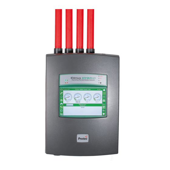
Page 6: Cirrus Hybrid General Component Overview
Product Manufacture Label Figure 1.0 Cirrus Hybrid External Components LED Status Indication Supply Heathy Fault Pre-Alarm Fire 1 to 3 Figure 1.1 Cirrus Hybrid LED Status Indication N93-600-00 Issue 4 Page 6 of 47 © Protec Fire Detection PLC 2015... -
Page 7: Internal Component Overview
Sample Inlet, Purge & Vacuum Outlet Unit Wall Fixing Points Front Door (Rear View) Label: Wiring Diagram Hybrid scanning unit only Figure 1.2 Cirrus Hybrid Internal Components N93-600-00 Issue 4 Page 7 of 47 © Protec Fire Detection PLC 2015... -
Page 8: Front Door Assembly Component Overview
Ribbon Cable to Cloud Chamber and Zone Scanning Unit Ethernet Connection TCPIP (RJ45) USB_B Computer Connection Camera Connection (RJ45) Touch Display Calibration Reset Button Figure 1.3 Cirrus Hybrid Front Door Assembly Components N93-600-00 Issue 4 Page 8 of 47 © Protec Fire Detection PLC 2015... -
Page 9: Installation
To remove the front cover unscrew the top and bottom screws using a cross head driver, and push in the top and bottom of the cover to un-clip then pull. N93-600-00 Issue 4 Page 9 of 47 © Protec Fire Detection PLC 2015... -
Page 10: Accessing The Terminal Connections
The display moulding is hinged, unscrew the two captive screw to open the hinged door, and behind the moulding are the terminal connections. Hinged front panel retaining screws Select and remove the required knock outs N93-600-00 Issue 4 Page 10 of 47 © Protec Fire Detection PLC 2015... -
Page 11: Drill Template
Drill Template N93-600-00 Issue 4 Page 11 of 47 © Protec Fire Detection PLC 2015... -
Page 12: Fixing To The Wall
Mark the mounting surface with the three mounting points using the mounting drill template or the unit itself. Remove the Cirrus Hybrid from the drilling area and drill the mounting points. Mount the case on the wall using the three mounting holes. Ensure unit is level in all planes. -
Page 13: Cirrus Hybrid General
Cirrus Hybrid General Introduction The Cirrus Hybrid utilises both Cloud Chamber and Scatter Chamber detectors to monitor for Fire and Smoke through an aspirating pipe system. These two technologies are used together to combine the best attributes of each technology in an algorithm based system. -
Page 14: Scatter Chamber
The scatter chamber detector in the Cirrus Hybrid is very sensitive, many times more than that of the point detector and so can be used in an aspirating system which has considerable dilution from clean areas. -
Page 15: Display
For quick navigation there are a series of icons permanently displayed on either side of the page / screen. Buzzer The Cirrus Hybrid is fitted with an internal buzzer. The buzzer will sound when the unit is in Fault, Pre- alarm or Fire. -
Page 16: Quick Navigation Icons
Input – Output Settings – Section 7.6 Section 7.12 System Text & Alarm Text – Section 7.7 Pipe Map – Section 7.13 Scroll Down a line (hold for fast scroll) N93-600-00 Issue 4 Page 16 of 47 © Protec Fire Detection PLC 2015... -
Page 17: Access Code
The access level timeouts after 4 minutes from the last keypress/screen touch. Pressing the red icon logs the user out. The default access code can be changed from the access code menu screen N93-600-00 Issue 4 Page 17 of 47 © Protec Fire Detection PLC 2015... -
Page 18: Saving The Hardware Configuration
Saving the Hardware Configuration When removing or adding device/s to/from the Cirrus Hybrid the unit needs to be told to learn its new configuration. This is done after entering the access code. Go to the bottom of all the menus using the to scoll to the bottom (hold down to increase speed).Where... -
Page 19: Faults
6.8.2 Device Added Fault A Cirrus Hybrid device has been added to the unit but the unit has not been commissioned to enable the device. The device will NOT detect fires. Refer to saving hardware configuration in section 6.6 . -
Page 20: Airflow Fault
At the time of commissioning when the pipe configurations are complete the airflow reading is to be zeroed. The Cirrus Hybrid sets the normalised zeroed value to 100%. If the airflow reading has drifted out of the fault tolerance range an airflow fault is generated. -
Page 21: Seal Fault
Cause Replace pump if not Damage/malfunctioning vacuum pump operating correctly Action Cause Replace cloud chamber Damage/malfunctioning valve detector unit is fault Internal leak/blockage persists N93-600-00 Issue 4 Page 21 of 47 © Protec Fire Detection PLC 2015... -
Page 22: Cloud Chamber Led Fault
Check the purge pipe or cloud chamber and replace as necessary. N93-600-00 Issue 4 Page 22 of 47 © Protec Fire Detection PLC 2015... -
Page 23: High Optical Background
Read Only Memory (ROM). 6.8.19 Unit Isolated The units Alarm Relays have been isolated via a monitored input. N93-600-00 Issue 4 Page 23 of 47 © Protec Fire Detection PLC 2015... -
Page 24: Airflow Ignored
Incorrect Device Type The SCD fitted is the incorrect type for the Hybrid. Types include Hybrid SCD and ProPoint PLUS SCD. Events The Cirrus Hybrid stores operational events within the internal memory ‘event log’. The following events are logged. Processor Fault The internal processor hardware has unexpectedly reset. -
Page 25: Commissioning The Cirrus Hybrid Using The Display
Commissioning the Cirrus Hybrid using the display Once the engineer access code has been correctly entered the user can begin to commission the Cirrus Hybrid detector. Refer to section 8.0 for commissioning using PC software. NOTE: The following example displays are shown for all four pipe channels. -
Page 26: Home Page
7.1.1 Holding on a pipe The Cirrus Hybrid scanning unit is capable of holding on a chosen pipe. Therefore continuously sampling on the chosen halted pipe only. To hold a pipe, ensure you are logged in as an engineer. Select the pipe text located under the CFS dial of the chosen pipe to be halted. -
Page 27: Setting The Date And Time
Set the date: navigate the >> arrows to the correct year navigate the > arrows to the correct month then click the correct day. N93-600-00 Issue 4 Page 27 of 47 © Protec Fire Detection PLC 2015... -
Page 28: Airflow & Fan Settings
‘Airflow Faults Latch’ box, vice versa to disable. Once enabled the airflow faults will latch and can be only be cleared by selecting either ‘Clear Airflow Faults’ or re-zeroing the airflow by selecting ‘Zero Airflow Reading’. N93-600-00 Issue 4 Page 28 of 47 © Protec Fire Detection PLC 2015... -
Page 29: Sensitivity Settings
Providing the ‘timezone’ is enabled in the Day / Night mode menu the alarm level can be set for each pipe, on each day, of each time zone (day & night). N93-600-00 Issue 4 Page 29 of 47 © Protec Fire Detection PLC 2015... -
Page 30: Time Zone Settings
Using the timezone 24 hour clock drag the two semi circles to the new time. The adjustable clock moves in 15minute increments. Set the timezone for each pipe on each day. The home screen will display to indicate the pipe night mode is activated. N93-600-00 Issue 4 Page 30 of 47 © Protec Fire Detection PLC 2015... -
Page 31: Input & Output Settings
‘output override fault’ to remind the user to un-select the ‘check to test’ box. The Cirrus Hybrid consists of 5 clean contact outputs. The operation of the outputs can be user configured to change state upon the following functions. Also each output can be configured to delay its activation. -
Page 32: System Text
The intention is to allow the user to customise the unit pipe & alarm text; to provide a quick visual aid to the area / zone to which the detector pipes are monitoring. N93-600-00 Issue 4 Page 32 of 47 © Protec Fire Detection PLC 2015... -
Page 33: Site, Manufacturing And Service Information
Pipe operating range (min & max) CFS value. The range is averaged slowy over time. Internal pipe temperature monitoring in each SCD. Average time between each water fill, estimating when the water bottle will be empty. N93-600-00 Issue 4 Page 33 of 47 © Protec Fire Detection PLC 2015... -
Page 34: Access Codes
The network menu displays: Protec Loop serial number. Protec address for each pipe assigned by the Protec fire panel IP address, Subnet Mask and Gateway either automatically assigned by network or manually inputted as a fixed address. -
Page 35: Event Log, Real Time And Historic Graph
The Cirrus Hybrid stores all fire, faults and events in the event log. The event log can store a maxmium of 256 events. Once the maxmium number of events is reached, new events are stored while the oldest events are removed (FIFO). -
Page 36: Historic Graph
7.11.3 Historic Graph The Cirrus Hybrid displays a historic graph of the optical, combined fire and smoke (CFS) and cloud values. To save memory; in normal condition the graph is updated every 4min, in a sudden raise of optical/CO the graph updates every 10secs. The plots are viewable for each pipe by selecting the tabs shown top left of the plot. -
Page 37: Adding A Camera With A Fixed Ip Address
If installing 2 or more cameras set a fixed IP address in each camera, follow the manufacturer’s instructions. 4. Open the ‘interfaces’ file (open in a wordpad type program to edit) 5. Edit the Cirrus Hybrid unit network to a fixed address, for example if the default IP address is 192.0.0.64; address 192.0.0.65 gateway 192.0.0.1... -
Page 38: Pipe Map
To change the image. Connect the Cirrus Hybrid to a PC running ProVeiw.exe. Select the tab ‘Detector’ and select ‘Change logo’. Browse and open the image file. To remove the image and default to the Cirrus Hybrid logo. Connect the Cirrus Hybrid to a PC running ProVeiw.exe. Select the tab ‘Detector’ and select ‘Remove logo’. -
Page 39: Commissioning The Cirrus Hybrid Using Pc Software
The following section details the instructions for using the ProView.exe commissioning PC software with the Cirrus Hybrid. Although most options are commissionable via the touch screen display menu, the PC software offers the same display menu with ease of editing and a log to file feature. The log to file feature saves the event log and the saves the historic data log to the PC. -
Page 40: Operating Proveiw.exe
ProView.exe does not require any installation, run ProVeiw.exe. ProVeiw.exe will open automatically connect to the Cirrus Hybrid unit. If it does not re-move and re-connect the USB cable. Once connect the ProVeiw.exe software will automatically open the default internet browser connecting the Cirrus Hybrid. If this does not happen right click on the ProView.exe icon on the lower right hand tool bar and click connect. -
Page 41: Network Cable Routing
1. Turn off the power supply to the Cirrus Hybrid unit. 2. Run ProVeiw.exe and connect the USB cable from the PC to the Cirrus Hybrid. Refer to section 8.3. 3. The ProVeiw.exe window console will display ‘Connected to bootloader’. -
Page 42: Loading The Webpage
The following instructions are to update the Cirrus Hybrid with a new version of web page software. 1. Run ProVeiw.exe and connect the USB cable from the PC to the Cirrus Hybrid. Refer to section 8.3. 2. Connect to the Cirrus Hybrid. If a web browsers is open close it. -
Page 43: Maintenance
Re-assemble the filters, replace the Scatter Chamber Detector (SCD) in position. Secure the two captive screws and replace the front cover. Test to ensure the unit still operates correctly. Components must be positioned upright for correct and accurate operation. N93-600-00 Issue 4 Page 43 of 47 © Protec Fire Detection PLC 2015... -
Page 44: Cloud Chamber Water Requirements
(<50% R.H) or high ambient temperature (>30C) conditions will increase the water usage. Periodic Checks and Maintenance The Cirrus Hybrid continuously adjusts its monitoring functions by means of feedback loops, ensuring a minimum of maintenance. To ensure continued correct operation, the system must be checked: ... -
Page 45: Technical Specifications
1.1A maximum at 24V (blower set to 100%, 4 Pipe Detector) Consumption Protec Algo-tec™ 6000 Loop Protocol Loop Isolator On board consult Protec DEL2110 for details Loop Quiescent Current 0.7mA Consumption Fault Contact Rated at 30 V maximum [Normally closed]... -
Page 46: General Cabling Requirements
Power supply fault monitor. No Fault input = 24 V Fault Clean Contact [30 V , 1 A maximum] Programmable Clean Contact Outputs [30 V , 1 A maximum] N93-600-00 Issue 4 Page 46 of 47 © Protec Fire Detection PLC 2015 Protec Digital Addressing Loop In... -
Page 47: Wiring Diagram
Figure 9.1 Cirrus Hybrid wiring diagram 11.2 Protec Digital Addressing Loop Wiring The figure 9.2 details the require wiring for Protec digital address loop, wiring as a ring or loop. Loop screens must be connected to the other loop screens only Figure 9.2 Protec digital addressing loop wiring diagram...
Need help?
Do you have a question about the CIRRUS HYBRID and is the answer not in the manual?
Questions and answers
How often does the system automatically check the water level in the cloud chamber?